CN202490943U - Double-tool-rest actuating mechanism of lathe and multifunctional numerical control lathe adopting same - Google Patents
Double-tool-rest actuating mechanism of lathe and multifunctional numerical control lathe adopting same Download PDFInfo
- Publication number
- CN202490943U CN202490943U CN2012200164898U CN201220016489U CN202490943U CN 202490943 U CN202490943 U CN 202490943U CN 2012200164898 U CN2012200164898 U CN 2012200164898U CN 201220016489 U CN201220016489 U CN 201220016489U CN 202490943 U CN202490943 U CN 202490943U
- Authority
- CN
- China
- Prior art keywords
- lathe
- circular cross
- linear motor
- section
- slide
- Prior art date
- Legal status (The legal status is an assumption and is not a legal conclusion. Google has not performed a legal analysis and makes no representation as to the accuracy of the status listed.)
- Expired - Fee Related
Links
- 230000007246 mechanism Effects 0.000 title abstract description 8
- 230000008859 change Effects 0.000 claims abstract description 7
- 238000009434 installation Methods 0.000 abstract description 8
- 230000005540 biological transmission Effects 0.000 description 7
- 230000033001 locomotion Effects 0.000 description 3
- 238000000034 method Methods 0.000 description 3
- 238000002485 combustion reaction Methods 0.000 description 2
- 238000006073 displacement reaction Methods 0.000 description 2
- 238000003754 machining Methods 0.000 description 2
- 230000008569 process Effects 0.000 description 2
- 230000004048 modification Effects 0.000 description 1
- 238000012986 modification Methods 0.000 description 1
- 230000004044 response Effects 0.000 description 1
Images


Landscapes
- Turning (AREA)
Abstract
本实用新型公开了一种车床双刀架执行机构及采用该机构的多功能数控车床,其是在现有数控车床执行机构的基础上,在圆形截面车削滑台的一侧并列平行安装沿垂直于车床主轴轴线方向移动的非圆截面车削滑台,在非圆截面车削滑台上导向装配由直线电机驱动沿垂直于车床主轴轴线方向移动的伺服刀架,在加工非圆截面工件时利用非圆截面车削滑台上直线电机驱动伺服刀架高速往复运动,实现非圆截面工件的车削加工,该车床结构简单,无须对现有普通数控车床平床身结构作任何改动,利用现有平床身工作滑台实现车床双刀架的安装,不仅提高产品的经济性和适应性,而且由于其无需改变现有的车床结构,既保证了车床双刀架执行机构的安装、使用和调试的方便性,又节省了车床的开发成本。
The utility model discloses a lathe double-turret actuator and a multifunctional numerically controlled lathe using the mechanism. The utility model is based on the existing numerically controlled lathe actuator, and is installed side by side on one side of a circular section turning slide table in parallel. The non-circular cross-section turning slide that moves perpendicular to the axis of the lathe spindle is guided and assembled on the non-circular cross-section turning slide. The servo tool holder that is driven by a linear motor and moves along the direction perpendicular to the axis of the lathe spindle is used when processing non-circular cross-section workpieces The linear motor on the non-circular section turning slide table drives the servo tool post to reciprocate at high speed to realize the turning processing of non-circular section workpieces. The lathe has a simple structure and does not need to make any changes to the existing flat bed structure of ordinary CNC lathes. The working slide realizes the installation of the double turret of the lathe, which not only improves the economy and adaptability of the product, but also ensures the convenience of installation, use and debugging of the lathe double turret actuator because it does not need to change the existing lathe structure. , and save the development cost of the lathe.
Description
技术领域 technical field
本实用新型涉及一种数控车床,准确的说是涉及一种能够加工内燃机活塞等非圆截面工件的车床双刀架执行机构及使用该执行机构的多功能数控车床。The utility model relates to a numerically controlled lathe, in particular to a double-turret actuator of the lathe capable of processing non-circular cross-section workpieces such as pistons of internal combustion engines and a multifunctional numerically controlled lathe using the actuator.
背景技术 Background technique
现有的普通数控车床主要包括床身、内设车床主轴的工件驱动箱、导向滑动装配于床身上沿车床主轴轴线方向移动的工作滑台及沿垂直于车床主轴轴线方向导向装配于工作滑台上的刀具滑台组成,工作滑台和刀具滑台均由对应设置的伺服电机通过丝杠螺母传动机构驱动沿导轨移动,这种数控车床只能加工圆形截面工件,而对于非圆截面的工件,如高速内燃机活塞,其加工能力和加工精度受伺服电机和丝杠螺母传动机构限制而无法加工。Existing ordinary CNC lathes mainly include a bed, a workpiece drive box with a lathe spindle inside, a work slide that is guided and slidably assembled on the bed to move along the axis of the lathe spindle, and a work slide that is guided and assembled on the bed in a direction perpendicular to the axis of the lathe spindle. Both the working slide and the tool slide are driven by the corresponding servo motor through the screw nut transmission mechanism to move along the guide rail. This kind of CNC lathe can only process circular cross-section workpieces, while for non-circular cross-section Workpieces, such as high-speed internal combustion engine pistons, cannot be machined due to the limitations of servo motors and lead screw nut transmission mechanisms in terms of machining capacity and machining accuracy.
实用新型内容 Utility model content
本实用新型的目的是:提供一种车床双刀架执行机构,以解决现有数控车床无法加工非圆截面工件的问题。The purpose of the utility model is to provide a lathe double-turret actuator to solve the problem that the existing numerical control lathe cannot process non-circular cross-section workpieces.
该车床双刀架执行机构的技术方案是:一种车床双刀架执行机构,包括用于沿车床主轴轴线方向导向装配在车床床身上的工作滑台,在工作滑台上导向装配有用于沿垂直于车床主轴轴线方向运动的圆形截面车削滑台,在该圆形截面车削滑台上安装有回转式车床刀架,在所述工作滑台上还与所述圆形截面车削滑台并列平行装配有用于沿垂直于车床主轴轴线方向移动的非圆截面车削滑台,在该非圆截面车削滑台上通过直线电机安装有用于沿垂直于车床主轴轴线方向移动的伺服刀架,所述直线电机的定子固定在非圆截面车削滑台上,所述伺服刀架固定安装在直线电机的动子上。The technical solution of the lathe double tool post actuator is: a lathe double tool post actuator, including a working slide for guiding and assembling on the lathe bed along the axis direction of the lathe spindle, and guiding and assembling on the working slide A circular cross-section turning slide that moves perpendicular to the axis of the lathe spindle, on which a rotary lathe tool holder is installed, and on the working slide, it is also juxtaposed with the circular cross-section turning slide A non-circular cross-section turning slide table for moving in a direction perpendicular to the axis of the lathe spindle is installed in parallel, and a servo tool holder for moving in a direction perpendicular to the axis of the lathe spindle is installed on the non-circle cross-section turning slide by a linear motor. The stator of the linear motor is fixed on the non-circular section turning slide table, and the servo tool rest is fixedly installed on the mover of the linear motor.
所述直线电机为圆筒形直线电机,该圆筒形直线电机通过其圆筒形的定子固定安装在非圆截面车削滑台上垂直固设的连接板上,所述的伺服刀架固定在该圆筒形直线电机动子上远离所述连接板的一端。The linear motor is a cylindrical linear motor, and the cylindrical linear motor is fixedly installed on the connecting plate vertically fixed on the non-circular section turning slide table through its cylindrical stator, and the servo tool holder is fixed on the The end of the cylindrical linear motor mover away from the connecting plate.
在所述伺服刀架的底部沿其移动方向设有导向槽,在非圆截面车削滑台上固设有与该导向槽导向滑动配合的直线导轨。A guide groove is provided at the bottom of the servo tool holder along its moving direction, and a linear guide rail that is slidably matched with the guide groove is fixed on the non-circular section turning slide table.
所述的非圆截面车削滑台及圆形截面车削滑台均通过底部开设的燕尾槽与工作滑台上对应固设的直线导轨滑动导向配合。Both the non-circular cross-section turning slide and the circular cross-section turning slide cooperate with the corresponding fixed linear guide rails on the working slide through the dovetail groove provided at the bottom.
所述的回转式车床刀架为通用四工位回转式自动换刀刀架。The rotary lathe tool post is a universal four-station rotary automatic tool change tool post.
本实用新型同时还提供了一种安装有上述车床双刀架执行机构的多功能数控车床,该多功能数控车床的技术方案是:一种多功能数控车床,包括床身、内设车床主轴的工件驱动箱及安装有切削刀具的车床执行机构,所述车床执行机构包括沿车床主轴轴线方向前后移动的导向装配在床身上的工作滑台,在工作滑台上沿垂直于车床主轴轴线方向导向装配有圆形截面车削滑台,在该圆形截面车削滑台上安装有回转式车床刀架,在所述工作滑台上还与所述圆形截面车削滑台并列平行装配有沿垂直于车床主轴轴线方向移动的非圆截面车削滑台,在该非圆截面车削滑台上通过直线电机安装有用于沿垂直于车床主轴轴线方向移动的伺服刀架,所述直线电机的定子固定在非圆截面车削滑台上,所述伺服刀架固定安装在直线电机的动子上。At the same time, the utility model also provides a multifunctional numerically controlled lathe equipped with the above-mentioned lathe double turret actuator. The workpiece drive box and the lathe actuator installed with cutting tools, the lathe actuator includes a guide that moves back and forth along the axis of the lathe spindle. Equipped with a circular cross-section turning slide, a rotary lathe tool holder is installed on the circular cross-section turning slide, and on the working slide, parallel to the circular cross-section turning slide, a A non-circular cross-section turning slide that moves in the direction of the lathe spindle axis, on which a linear motor is installed on the non-circular cross-section turning slide for moving in a direction perpendicular to the lathe spindle axis. The stator of the linear motor is fixed on a non-circular On the circular cross-section turning slide table, the servo tool holder is fixedly installed on the mover of the linear motor.
所述直线电机为圆筒形直线电机,该圆筒形直线电机通过其圆筒形的定子固定安装在非圆截面车削滑台上垂直固设的连接板上,所述的伺服刀架固定在该圆筒形直线电机动子上远离所述连接板的一端。The linear motor is a cylindrical linear motor, and the cylindrical linear motor is fixedly installed on the connecting plate vertically fixed on the non-circular section turning slide table through its cylindrical stator, and the servo tool holder is fixed on the The end of the cylindrical linear motor mover away from the connecting plate.
在所述伺服刀架的底部沿其移动方向设有导向槽,在非圆截面车削滑台上固设有与该导向槽导向滑动配合的直线导轨。A guide groove is provided at the bottom of the servo tool holder along its moving direction, and a linear guide rail that is slidably matched with the guide groove is fixed on the non-circular section turning slide table.
所述的回转式车床刀架为通用四工位回转式自动换刀刀架。The rotary lathe tool post is a universal four-station rotary automatic tool change tool post.
所述的非圆截面车削滑台及圆形截面车削滑台均通过底部开设的燕尾槽与工作滑台上对应固设的直线导轨滑动导向配合。Both the non-circular cross-section turning slide and the circular cross-section turning slide cooperate with the corresponding fixed linear guide rails on the working slide through the dovetail groove provided at the bottom.
本实用新型在现有数控车床执行机构的基础上,在圆形截面车削滑台的一侧并列平行安装沿垂直于车床主轴轴线方向移动的非圆截面车削滑台,在非圆截面车削滑台上导向装配由直线电机驱动沿垂直于车床主轴轴线方向移动的伺服刀架,形成双刀架结构,在加工圆形截面工件时采用圆形截面车削滑台,在加工非圆截面工件时采用非圆截面车削滑台,利用直线电机的高频响应特性驱动伺服刀架高速往复运动,从而实现非圆截面工件的车削加工,该车床结构简单,无须对现有普通数控车床平床身结构作任何改动,利用现有平床身工作滑台实现车床双刀架的安装,不仅提高产品的经济性和适应性,而且由于其无需改变现有的车床结构,既保证了车床双刀架执行机构的安装、使用和调试的方便性,又节省了车床的开发成本。On the basis of the existing CNC lathe executive mechanism, the utility model installs the non-circular section turning slide table in parallel on one side of the circular section turning slide table and moves along the direction perpendicular to the lathe spindle axis, and the non-circular section turning slide table The upper guide assembly is driven by a linear motor to move the servo tool holder in the direction perpendicular to the axis of the lathe spindle, forming a double tool holder structure. When processing circular cross-section workpieces, the circular cross-section turning slide table is used, and when the non-circular cross-section workpiece is processed, the non-circular cross-section is used. The circular section turning slide table uses the high-frequency response characteristics of the linear motor to drive the servo tool post to reciprocate at high speed, thereby realizing the turning processing of non-circular section workpieces. The lathe has a simple structure and does not need to make any changes to the existing ordinary CNC lathe flat bed structure. , using the existing flat bed working slide table to realize the installation of the double turrets of the lathe, which not only improves the economy and adaptability of the product, but also ensures the installation of the lathe double turret actuators, The convenience of use and debugging saves the development cost of the lathe.
附图说明 Description of drawings
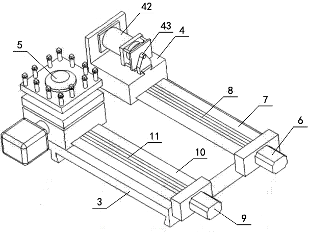
图1为本实用新型中多功能数控车床具体实施例的结构示意图;Fig. 1 is the structural representation of the specific embodiment of multifunctional numerically controlled lathe in the utility model;
图2为图1中车床执行机构的立体结构示意图。Fig. 2 is a schematic perspective view of the three-dimensional structure of the lathe actuator in Fig. 1 .
具体实施方式 Detailed ways
本实用新型的多功能数控车床具体实施例如图1所示,该数控车床的床身1上固定安装有内设车床主轴的工件驱动箱2及用于安装切削刀具的车床执行机构。其中,车床执行机构包括通过床身1上固定的导轨导向安装于工件驱动箱一侧、沿车床主轴轴线方向移动的工作滑台3,工作滑台3上并列平行导向装配有两个沿垂直于车床主轴方向移动的刀具滑台,其中,靠近工件驱动箱2一侧的刀具滑台为非圆截面车削滑台4,远离工件驱动箱2一侧的刀具滑台为圆形截面车削滑台5。本实施例中,如图2所示,非圆截面车削滑台4通过底部开设的燕尾槽导向滑动装配于工作滑台3上对应设置的直线导轨7上,圆形截面车削滑台5通过底部开设的燕尾槽导向滑动装配在工作滑台3上对应设置的直线导轨10上,在工作滑台3的一侧分别对应非圆截面车削滑台4和圆形截面车削滑台5安装有两伺服电机6、9,其中,非圆截面车削滑台4通过对应设置的丝杠螺母传动机构8与伺服电机6传动连接,圆形截面车削滑台5通过对应设置的丝杠螺母传动机构11与另一伺服电机9传动连接。在圆形截面车削滑台5上固定安装有通用的四工位回转式自动换刀刀架,在该刀架上通过螺钉可以固定安装四把车床用刀具,根据需要自动转动换刀,这种四工位回转式自动换刀刀架为现有技术,此处不再赘述,该圆形截面车削滑台5通过对应的伺服电机9及丝杠螺母传动机构11驱动沿垂直于车床主轴方向往复移动,主要用于普通圆形截面工件的车削加工;在非圆截面车削滑台4上安装有沿垂直于车床主轴方向往复动作的直线电机42,本实施例中,该直线电机42采用BOB圆筒形直线电机,该直线电机42的筒状定子固定在非圆截面车削滑台4,在该直线电机42的动子末端安装有伺服刀架43,该伺服刀架43的上部设有一个车削刀具安装工位,可以固定安装一把车削刀具,该伺服刀架43的下部通过燕尾槽与非圆截面车削滑台4上对应设置的直线导轨导向滑动配合,该非圆截面车削滑台4上通过对应的伺服电机6及直线电机42的驱动,可以分别带动伺服刀架43沿垂直于车床主轴方向作直线运动或高频微位移运动,也可以进行两个运动的叠加,主要用于实现非圆截面工件的车削加工。The specific embodiment of the multifunctional numerical control lathe of the present invention is shown in Figure 1. The
本实用新型的车床双刀架执行机构主要由沿车床主轴轴线方向导向装配在床身上的工作滑台3及沿垂直于车床主轴轴线方向并列导向滑动装配在工作滑台上的两刀具滑台组成,两刀具滑台中靠近工件驱动箱2一侧的为非圆截面车削滑台4,远离工件驱动箱2一侧的为圆形截面车削滑台5,其具体结构在上述实施例中已有详细描述,此处不再赘述。The lathe double-turret actuator of the utility model is mainly composed of a working
本实用新型的非圆截面工件数控车床结构简单、传动平稳,车床双刀架执行机构运行稳定可靠,能够有效保证对刀具位移的精确控制,而且该数控车床无须对现有普通数控车床平床身结构作任何改动,其仅利用现有平床身工作滑台的安装位置即可实现双刀架的安装,根据加工需要采用不同的滑台实现圆形截面工件与非圆截面工件的加工,充分的提高了该数控车床的经济性和适应性,同时,由于本实用新型的数控车床不改变现有车床结构,因此其既保证了机床双刀架的安装、使用和调试的方便性,又节省了数控车床的开发成本。The CNC lathe for non-circular cross-section workpieces of the utility model has simple structure, stable transmission, stable and reliable operation of the double-turret actuators of the lathe, and can effectively ensure precise control of tool displacement, and the CNC lathe does not need to modify the flat bed structure of the existing common CNC lathe Without any modification, it can realize the installation of double tool holders only by using the installation position of the existing flat bed working slide table. According to the processing needs, different slide tables can be used to realize the processing of circular cross-section workpieces and non-circular cross-section workpieces, which fully improves The economy and adaptability of the CNC lathe are improved. At the same time, because the CNC lathe of the present invention does not change the structure of the existing lathe, it not only ensures the convenience of installation, use and debugging of the double tool rest of the machine tool, but also saves the CNC lathe. The development cost of the lathe.
Claims (10)
Priority Applications (1)
| Application Number | Priority Date | Filing Date | Title |
|---|---|---|---|
| CN2012200164898U CN202490943U (en) | 2012-01-14 | 2012-01-14 | Double-tool-rest actuating mechanism of lathe and multifunctional numerical control lathe adopting same |
Applications Claiming Priority (1)
| Application Number | Priority Date | Filing Date | Title |
|---|---|---|---|
| CN2012200164898U CN202490943U (en) | 2012-01-14 | 2012-01-14 | Double-tool-rest actuating mechanism of lathe and multifunctional numerical control lathe adopting same |
Publications (1)
| Publication Number | Publication Date |
|---|---|
| CN202490943U true CN202490943U (en) | 2012-10-17 |
Family
ID=46997187
Family Applications (1)
| Application Number | Title | Priority Date | Filing Date |
|---|---|---|---|
| CN2012200164898U Expired - Fee Related CN202490943U (en) | 2012-01-14 | 2012-01-14 | Double-tool-rest actuating mechanism of lathe and multifunctional numerical control lathe adopting same |
Country Status (1)
| Country | Link |
|---|---|
| CN (1) | CN202490943U (en) |
Cited By (6)
| Publication number | Priority date | Publication date | Assignee | Title |
|---|---|---|---|---|
| CN107309655A (en) * | 2017-08-22 | 2017-11-03 | 江苏精实数控精密机械有限公司 | The roller Sizing Pass machining tool of multifunctional numerical control three and its method of work |
| CN107363547A (en) * | 2017-08-08 | 2017-11-21 | 江西震恒实业有限公司 | Numerical control high-precision car, rolling all-in-one |
| CN108072536A (en) * | 2018-02-05 | 2018-05-25 | 吉林大学 | Semi-intelligent Modular numerical control servo knife rest mass reliability test and test method |
| CN110871278A (en) * | 2019-12-24 | 2020-03-10 | 东莞市中煌五金制品有限公司 | Simple automatic lathe's knife rest structure |
| CN111014744A (en) * | 2020-01-07 | 2020-04-17 | 金华市彩橙机床有限公司 | Machine tool rest |
| CN117381504A (en) * | 2023-11-16 | 2024-01-12 | 江苏美事科电机制造有限公司 | Feeding knife rest for turning non-circle and eccentric circle of numerical control lathe |
-
2012
- 2012-01-14 CN CN2012200164898U patent/CN202490943U/en not_active Expired - Fee Related
Cited By (7)
| Publication number | Priority date | Publication date | Assignee | Title |
|---|---|---|---|---|
| CN107363547A (en) * | 2017-08-08 | 2017-11-21 | 江西震恒实业有限公司 | Numerical control high-precision car, rolling all-in-one |
| CN107309655A (en) * | 2017-08-22 | 2017-11-03 | 江苏精实数控精密机械有限公司 | The roller Sizing Pass machining tool of multifunctional numerical control three and its method of work |
| CN108072536A (en) * | 2018-02-05 | 2018-05-25 | 吉林大学 | Semi-intelligent Modular numerical control servo knife rest mass reliability test and test method |
| CN108072536B (en) * | 2018-02-05 | 2023-09-08 | 吉林大学 | Semi-intelligent CNC servo tool holder batch reliability test device and test method |
| CN110871278A (en) * | 2019-12-24 | 2020-03-10 | 东莞市中煌五金制品有限公司 | Simple automatic lathe's knife rest structure |
| CN111014744A (en) * | 2020-01-07 | 2020-04-17 | 金华市彩橙机床有限公司 | Machine tool rest |
| CN117381504A (en) * | 2023-11-16 | 2024-01-12 | 江苏美事科电机制造有限公司 | Feeding knife rest for turning non-circle and eccentric circle of numerical control lathe |
Similar Documents
| Publication | Publication Date | Title |
|---|---|---|
| CN201086216Y (en) | Multifunctional numerical control machine tool | |
| US9381607B2 (en) | Feeding device and machine tool using the same | |
| JP2014121778A (en) | Lathe | |
| JP2014121777A (en) | Lathe | |
| CN102001027A (en) | Four-axis four-linkage vertical machining centre | |
| CN102380625A (en) | Special numerically controlled lathe for cutting inner arc curved surface | |
| CN202782416U (en) | Rotating head three-workstage carving machine | |
| CN201776618U (en) | Multistation modular machine tool | |
| JP6403944B2 (en) | Curved surface turning method | |
| JP5361563B2 (en) | lathe | |
| CN202162413U (en) | Numerical control high-speed hole puncher | |
| RU98350U1 (en) | MULTI-PURPOSE MACHINE WITH NUMERIC SOFTWARE CONTROL AND AUTOMATIC TOOL CHANGE | |
| CN207735623U (en) | A kind of bent axle twin tip drill of overhead tool magazine attacks center | |
| CN203092127U (en) | Lathing and grinding combined machining machine tool | |
| CN103521816A (en) | Numeric control horizontal single station ball cage milling machine | |
| CN102284880B (en) | C-axis device of numerical control vertical lathe | |
| CN104959865A (en) | Bamboo hat tool magazine in high tool changing precision | |
| CN104827350A (en) | Processing center with high tool change accuracy | |
| CN203711949U (en) | Digital-control horizontal type single-station ball cage milling machine | |
| CN203818255U (en) | Main machine tool subassembly for numerical control machining center | |
| CN202742143U (en) | Combined numerical control machine tool | |
| CN204725207U (en) | The 3rd axle group structure in scheming is walked in a kind of numerical control rip cutting | |
| CN202398842U (en) | Tool turret and numerical control lathe | |
| CN202180378U (en) | C-shaft device of numerical control vertical lathe | |
| CN105665751A (en) | Vertical numerically controlled lathe |
Legal Events
| Date | Code | Title | Description |
|---|---|---|---|
| C14 | Grant of patent or utility model | ||
| GR01 | Patent grant | ||
| C17 | Cessation of patent right | ||
| CF01 | Termination of patent right due to non-payment of annual fee |
Granted publication date: 20121017 Termination date: 20140114 |