CN202490889U - Fixed-core-model-type thin wall pipe precise rotary extrusion neck-reducing device - Google Patents
Fixed-core-model-type thin wall pipe precise rotary extrusion neck-reducing device Download PDFInfo
- Publication number
- CN202490889U CN202490889U CN2012200698683U CN201220069868U CN202490889U CN 202490889 U CN202490889 U CN 202490889U CN 2012200698683 U CN2012200698683 U CN 2012200698683U CN 201220069868 U CN201220069868 U CN 201220069868U CN 202490889 U CN202490889 U CN 202490889U
- Authority
- CN
- China
- Prior art keywords
- core
- model
- spinning
- fixed block
- diameter
- Prior art date
- Legal status (The legal status is an assumption and is not a legal conclusion. Google has not performed a legal analysis and makes no representation as to the accuracy of the status listed.)
- Expired - Fee Related
Links
Images
Landscapes
- Shaping Metal By Deep-Drawing, Or The Like (AREA)
Abstract
本实用新型公开了一种固定芯模式薄壁管精密旋压缩径装置,包括定位夹紧部分、管坯、旋压缩径成形及芯模整形部分;所述定位夹紧部分包括卡盘,所述卡盘连接有弹性套筒;所述管坯插入所述弹性套筒一起装夹在所述卡盘;所述旋压缩径成形及芯模整形部分包括固定块,所述固定块内连接有芯模,所述固定块一端连接有缩径凹模,所述缩径凹模内设有所述芯模,所述固定块另一端连接有尾架。本实用新型可装在普通车床或专用旋压机完成薄壁管精密旋压缩径成形,本实用新型主要适于中小批量生产的场合。
The utility model discloses a precision spinning and reducing diameter device for a thin-walled tube with a fixed core mode, which includes a positioning and clamping part, a tube blank, a spinning and reducing diameter forming and a mandrel shaping part; the positioning and clamping part includes a chuck, and the The chuck is connected with an elastic sleeve; the tube blank is inserted into the elastic sleeve and clamped on the chuck together; the part of the spinning compression diameter forming and core mold shaping part includes a fixed block, and the fixed block is connected with a core One end of the fixed block is connected with a diameter-reducing die, the core die is arranged inside the reduced-diameter die, and the other end of the fixed block is connected with a tailstock. The utility model can be installed on an ordinary lathe or a special spinning machine to complete the precision spinning and reducing diameter forming of thin-walled tubes. The utility model is mainly suitable for small and medium batch production occasions.
Description
技术领域 technical field
本实用新型涉及一种管材缩径成形工艺装置,具体涉及一种对薄壁管精密缩径的固定芯模式旋压缩径新装置。 The utility model relates to a pipe diameter reduction forming process device, in particular to a new fixed core mode spinning diameter reduction device for precise diameter reduction of thin-walled pipes.
背景技术 Background technique
在汽车、航天领域受减轻重量、降低成本和提高质量的推动,越来越多的零部件采用管材制造,管材缩径零件具有高效、优质、经济、强度高、刚度大等优点。管材经过推缩成形、拉拔成形等成形方法可以得到不同口径的零部件。但管材用于制造汽车、航天零部件,其成形方式主要采用开式模具的推缩成形。随着缩径零件的形状和尺寸精度要求的越来越高,推缩成形由无芯推缩成形发展到有芯推缩成形。有芯推缩成形的固定芯轴式、浮动芯轴式两类,其芯轴在开始缩径前都已进入管件,管件缩径成形时芯轴同时将处于定径区的管壁进行挤压变形,这将造成管件受到较大的轴向推挤力,易发生管壁部屈曲失稳变形。推缩成形主要有冲压缩径法、旋压成形等。冲压缩径法一次缩口工序的变形程度是有限的,主要限制因素是传力区管壁轴向压力过大时纵向失稳而出现环状皱纹或局部凹陷,或变形区管壁因切线方向压缩应力的作用易发生切向失稳起皱。为强化冲压缩径工序可采用加热缩口,设计专门的加热缩口的装置,但设备成本提高。旋压缩径法通常都设计专门的旋压机,成本较高,不适于中小批量管件的生产场合。所以需设计一种造价较低、效率高、产品精度高的管材缩径新装置。 Driven by weight reduction, cost reduction and quality improvement in the automotive and aerospace fields, more and more parts are made of pipes, and pipe reduced-diameter parts have the advantages of high efficiency, high quality, economy, high strength, and high rigidity. Parts with different diameters can be obtained by forming methods such as shrink forming and drawing forming of the pipe. However, the pipe is used to manufacture automobile and aerospace parts, and its forming method mainly adopts the push-shrink forming of the open mold. As the shape and dimensional accuracy of reduced-diameter parts become higher and higher, push-shrink forming has developed from coreless push-shrink forming to cored push-shrink forming. There are two types of fixed mandrel type and floating mandrel type with core pushing and shrinking. The mandrel has entered the pipe before the diameter is reduced. When the pipe is reduced in diameter, the mandrel simultaneously squeezes the pipe wall in the sizing area. Deformation, which will cause the pipe fittings to be subjected to a large axial pushing force, and buckling and instability deformation of the pipe wall are prone to occur. Push-shrink forming mainly includes punching and shrinking method, spinning forming and so on. The degree of deformation of the one-time necking process of the punching and shrinking method is limited. The main limiting factor is that when the axial pressure of the tube wall in the force transmission area is too large, the longitudinal instability will cause ring wrinkles or local depressions, or the tube wall in the deformation zone will be deformed due to the tangential direction. The effect of compressive stress is prone to tangential instability and wrinkling. In order to strengthen the stamping and shrinking process, heating shrinking can be used, and a special heating shrinking device is designed, but the equipment cost increases. Spinning and shrinking methods usually design a special spinning machine, which is expensive and not suitable for the production of small and medium batches of pipe fittings. Therefore, it is necessary to design a new pipe reducing device with low cost, high efficiency and high product precision.
实用新型内容 Utility model content
本实用新型的目的在于克服现有技术存在的以上问题,提供一种固定芯模式旋压缩径新装置,该装置具有结构简单、产品精度高的优点。 The purpose of the utility model is to overcome the above problems in the prior art, and provide a new device for rotating and compressing the diameter of the fixed core mode. The device has the advantages of simple structure and high product precision.
为实现上述技术目的,达到上述技术效果,本实用新型通过以下技术方案实现: In order to achieve the above-mentioned technical purpose and achieve the above-mentioned technical effect, the utility model is realized through the following technical solutions:
一种固定芯模式薄壁管精密旋压缩径新装置,包括定位夹紧部分、管坯、旋压缩径成形及芯模整形部分;所述定位夹紧部分包括卡盘,所述卡盘连接有弹性套筒;所述管坯插入所述弹性套筒一起装夹在所述卡盘;所述旋压缩径成形及芯模整形部分包括固定块,所述固定块内连接有芯模,所述固定块一端连接有缩径凹模,所述缩径凹模内设有所述芯模,所述固定块另一端连接有尾架。 A new device for precision spinning and reducing the diameter of a thin-walled tube with a fixed core mode, including a positioning and clamping part, a tube blank, a spinning and reducing diameter forming part, and a mandrel shaping part; the positioning and clamping part includes a chuck, and the chuck is connected with Elastic sleeve; the tube blank is inserted into the elastic sleeve and clamped on the chuck together; the part of the spinning compression diameter forming and core mold shaping part includes a fixed block, and the fixed block is connected with a core mold. One end of the fixed block is connected with a diameter-reducing die, and the core die is arranged inside the reduced-diameter die, and the other end of the fixed block is connected with a tailstock.
进一步的,所述固定块与所述芯模通过销钉连接。 Further, the fixing block is connected with the core mold through pins.
进一步的,所述固定块与所述缩径凹模通过螺钉连接。 Further, the fixing block is connected with the reducing die by screws.
本实用新型的有益效果是: The beneficial effects of the utility model are:
提供一种固定芯模式薄壁管精密旋压缩径新装置,本装置在普通车床或专用旋压机上,将管坯插入弹性套筒一起夹在卡盘上旋转,装在尾架内的旋压缩径模作纵向送进运动,利用旋压缩径模完成薄壁管缩径成形,缩口完毕,模具退出时利用芯模对缩口内径整形,可以保证缩径后有配合要求的内径精度和内壁的光洁度。由于缩口成形是逐渐进行的,故大大减小了缩径力及传力区产生失稳的危险。同时,由于管坯随车床主轴高速旋转,旋压缩径模与管壁摩擦发热,减小管材的变形抗力,有利于变形区材料的塑性变形,而传力区的管壁温度则比变形区的温度低,传力效能不受影响,因而可提高单次缩口的变形程度。旋压过程中用润滑油润滑并冷却避免温度过高时,存在管材与模具粘结的危险。本实用新型设计合理、结构简单、操作方便,产品精度高且性能好,造价低。本实用新型可装在普通车床或专用旋压机完成薄壁管精密旋压缩径成形,本实用新型主要适于中小批量生产的场合。 A new device for precision spinning and reducing the diameter of thin-walled tubes with fixed core mode is provided. This device is used on ordinary lathes or special spinning machines. The tube blank is inserted into the elastic sleeve and clamped on the chuck for rotation. The spinner installed in the tailstock The compression diameter die is used for longitudinal feeding movement, and the thin-walled tube diameter reduction is completed by using the rotary compression die. of smoothness. Since the necking is gradually carried out, the risk of instability in the shrinking force and force transmission area is greatly reduced. At the same time, due to the high-speed rotation of the tube blank with the lathe spindle, the friction between the spinning compression die and the tube wall heats up, reducing the deformation resistance of the tube, which is beneficial to the plastic deformation of the material in the deformation zone, and the temperature of the tube wall in the force transmission zone is higher than that in the deformation zone. The force transmission performance is not affected at low temperature, so the deformation degree of single necking can be improved. During the spinning process, lubricate with lubricating oil and cool to avoid excessive temperature, there is a danger of pipe and mold sticking. The utility model has the advantages of reasonable design, simple structure, convenient operation, high product precision and good performance, and low manufacturing cost. The utility model can be installed on an ordinary lathe or a special spinning machine to complete the precision spinning and reducing diameter forming of thin-walled tubes. The utility model is mainly suitable for small and medium batch production occasions.
上述说明仅是本实用新型技术方案的概述,为了能够更清楚了解本实用新型的技术手段,并可依照说明书的内容予以实施,以下以本实用新型的较佳实施例并配合附图详细说明如后。本实用新型的具体实施方式由以下实施例及其附图详细给出。 The above description is only an overview of the technical solution of the utility model. In order to understand the technical means of the utility model more clearly and implement it according to the contents of the specification, the following is a detailed description of the preferred embodiment of the utility model with accompanying drawings. back. The specific embodiment of the utility model is given in detail by the following examples and accompanying drawings.
附图说明 Description of drawings
此处所说明的附图用来提供对本实用新型的进一步理解,构成本申请的一部分,本实用新型的示意性实施例及其说明用于解释本实用新型,并不构成对本实用新型的不当限定。在附图中: The drawings described here are used to provide a further understanding of the utility model and constitute a part of the application. The schematic embodiments of the utility model and their descriptions are used to explain the utility model and do not constitute improper limitations to the utility model. In the attached picture:
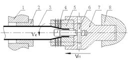
图1为本实用新型的旋压缩径模工作状态示意图; Fig. 1 is the schematic diagram of the working state of the rotary compression diameter die of the present utility model;
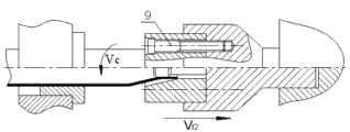
图2为本实用新型的芯模整形工作状态示意图。 Fig. 2 is a schematic diagram of the mandrel shaping working state of the utility model.
图中标号说明:1、卡盘,2、弹性套筒,3、管坯,4、芯模,5、缩径凹模,6、销钉,7、固定块,8、尾架,9、螺钉。 Explanation of symbols in the figure: 1, chuck, 2, elastic sleeve, 3, tube blank, 4, mandrel, 5, reducing die, 6, pin, 7, fixed block, 8, tailstock, 9, screw .
具体实施方式 Detailed ways
下面将参考附图并结合实施例,来详细说明本实用新型。 The utility model will be described in detail below with reference to the accompanying drawings and in conjunction with the embodiments.
参照图1所示,一种固定芯模式薄壁管精密旋压缩径新装置,包括定位夹紧部分A、管坯3、旋压缩径成形及芯模整形部分B;所述定位夹紧部分A包括卡盘1,所述卡盘1连接有弹性套筒2;所述管坯3插入所述弹性套筒2一起装夹在所述卡盘1;所述旋压缩径成形及芯模整形部分B包括固定块7,所述固定块7内连接有芯模4,所述固定块7一端连接有缩径凹模5,所述缩径凹模5内设有所述芯模4,所述固定块7另一端连接有尾架8。
As shown in Fig. 1, a new device for precision spinning and reducing the diameter of a thin-walled tube with a fixed core mode includes a positioning and clamping part A, a tube blank 3, a spinning and reducing diameter forming and a mandrel shaping part B; the positioning and clamping part A Including a chuck 1, the chuck 1 is connected with an
进一步的,所述固定块7与所述芯模4通过销钉6连接。
Further, the
进一步的,所述固定块7与所述缩径凹模5通过螺钉9连接。
Further, the
该装置工作时,首先,将管坯3插入弹性套筒2、并借助卡盘1夹紧;然后,机床工作,卡盘1和弹性套筒2夹持管坯3作旋转运动 


以上所述仅为本实用新型的优选实施例而已,并不用于限制本实用新型,对于本领域的技术人员来说,本实用新型可以有各种更改和变化。凡在本实用新型的精神和原则之内,所作的任何修改、等同替换、改进等,均应包含在本实用新型的保护范围之内。 The above descriptions are only preferred embodiments of the utility model, and are not intended to limit the utility model. For those skilled in the art, the utility model can have various modifications and changes. Any modification, equivalent replacement, improvement, etc. made within the spirit and principles of the present utility model shall be included in the protection scope of the present utility model.
Claims (3)
Priority Applications (1)
| Application Number | Priority Date | Filing Date | Title |
|---|---|---|---|
| CN2012200698683U CN202490889U (en) | 2012-02-29 | 2012-02-29 | Fixed-core-model-type thin wall pipe precise rotary extrusion neck-reducing device |
Applications Claiming Priority (1)
| Application Number | Priority Date | Filing Date | Title |
|---|---|---|---|
| CN2012200698683U CN202490889U (en) | 2012-02-29 | 2012-02-29 | Fixed-core-model-type thin wall pipe precise rotary extrusion neck-reducing device |
Publications (1)
| Publication Number | Publication Date |
|---|---|
| CN202490889U true CN202490889U (en) | 2012-10-17 |
Family
ID=46997133
Family Applications (1)
| Application Number | Title | Priority Date | Filing Date |
|---|---|---|---|
| CN2012200698683U Expired - Fee Related CN202490889U (en) | 2012-02-29 | 2012-02-29 | Fixed-core-model-type thin wall pipe precise rotary extrusion neck-reducing device |
Country Status (1)
| Country | Link |
|---|---|
| CN (1) | CN202490889U (en) |
Cited By (7)
| Publication number | Priority date | Publication date | Assignee | Title |
|---|---|---|---|---|
| CN102601199A (en) * | 2012-02-29 | 2012-07-25 | 苏州经贸职业技术学院 | Precise-spin reducing device for fixed core type thin wall pipe |
| CN104607550A (en) * | 2015-02-15 | 2015-05-13 | 苏州鸿普精密模具有限公司 | Automotive steering tubing connector servo cold punching mold |
| CN106825253A (en) * | 2015-09-10 | 2017-06-13 | 张琴 | The method of work of the stem reducing mould of positioning in a kind of pipe |
| CN106955941A (en) * | 2017-05-20 | 2017-07-18 | 郭远军 | A kind of diameter reducing working method and its used necking die and application |
| CN107008816A (en) * | 2017-05-20 | 2017-08-04 | 郭远军 | A kind of diameter reducing working method and its used necking die and application |
| CN108856410A (en) * | 2018-06-13 | 2018-11-23 | 开平市祺龙五金塑胶有限公司 | A kind of nozzle processing unit (plant) and its processing method |
| WO2022092269A1 (en) * | 2020-11-02 | 2022-05-05 | 中川特殊鋼株式会社 | Method for manufacturing stepped hollow shaft and method for manufacturing motor shaft |
-
2012
- 2012-02-29 CN CN2012200698683U patent/CN202490889U/en not_active Expired - Fee Related
Cited By (7)
| Publication number | Priority date | Publication date | Assignee | Title |
|---|---|---|---|---|
| CN102601199A (en) * | 2012-02-29 | 2012-07-25 | 苏州经贸职业技术学院 | Precise-spin reducing device for fixed core type thin wall pipe |
| CN104607550A (en) * | 2015-02-15 | 2015-05-13 | 苏州鸿普精密模具有限公司 | Automotive steering tubing connector servo cold punching mold |
| CN106825253A (en) * | 2015-09-10 | 2017-06-13 | 张琴 | The method of work of the stem reducing mould of positioning in a kind of pipe |
| CN106955941A (en) * | 2017-05-20 | 2017-07-18 | 郭远军 | A kind of diameter reducing working method and its used necking die and application |
| CN107008816A (en) * | 2017-05-20 | 2017-08-04 | 郭远军 | A kind of diameter reducing working method and its used necking die and application |
| CN108856410A (en) * | 2018-06-13 | 2018-11-23 | 开平市祺龙五金塑胶有限公司 | A kind of nozzle processing unit (plant) and its processing method |
| WO2022092269A1 (en) * | 2020-11-02 | 2022-05-05 | 中川特殊鋼株式会社 | Method for manufacturing stepped hollow shaft and method for manufacturing motor shaft |
Similar Documents
| Publication | Publication Date | Title |
|---|---|---|
| CN102601199A (en) | Precise-spin reducing device for fixed core type thin wall pipe | |
| CN202490889U (en) | Fixed-core-model-type thin wall pipe precise rotary extrusion neck-reducing device | |
| CN106270058B (en) | S-shaped Curved Continuous duct forming method and its device | |
| CN201127971Y (en) | CNC pipe bender mold for hot bending | |
| CN204974900U (en) | Thin -walled metal tube spinning device | |
| CN205950330U (en) | Thin wall cylindric class part cylindrical turning frock | |
| CN113399529A (en) | Composite forming method for paired wheel spinning and double-roller clamping spinning of thin-wall rotary part | |
| CN101214609B (en) | A kind of preparation method of motor vehicle nylon hose molding die | |
| CN108941243B (en) | A kind of iron-based/nickel-titanium-based shape memory alloy composite pipe manufacturing method | |
| CN105689544A (en) | Shot tube bending machine and quick short tube bending process thereof | |
| CN205200367U (en) | A expand throat machine for soft steel pipe | |
| CN204843019U (en) | Eccentric clamping device for parts machining | |
| CN108620466B (en) | A kind of mold for CNC bending of double-layer pipe and its forming method | |
| CN222491652U (en) | Split type return bend plug device | |
| CN201880809U (en) | Universal spinning closing-in device for guide pipes | |
| CN111151631A (en) | Multi-pass spinning forming clamping structure and spinning method for variable cross-section guide pipe of oil tank | |
| CN108723217A (en) | Pipe end clamping device and its clamping means on a kind of electric tube expander | |
| CN200951445Y (en) | Double-layer ball spinning device | |
| CN208912976U (en) | A kind of air-conditioning copper tube end reducing device | |
| CN106238548A (en) | The adjustable feed arrangement of outward turning diameter in a kind of Opposite roller spinning equipment | |
| CN101579712A (en) | Auxiliary expansion set | |
| CN116984448A (en) | A kind of duct type groove rolling wave forming tooling | |
| CN105665513B (en) | A kind of forming method of processed complex variable cross-section small-sized tube | |
| CN209189725U (en) | Vertical-type screw screw-rolling machine | |
| CN207914456U (en) | A kind of bend pipe thickens tooling |
Legal Events
| Date | Code | Title | Description |
|---|---|---|---|
| C14 | Grant of patent or utility model | ||
| GR01 | Patent grant | ||
| C17 | Cessation of patent right | ||
| CF01 | Termination of patent right due to non-payment of annual fee | ||
| CF01 | Termination of patent right due to non-payment of annual fee |
Granted publication date: 20121017 Termination date: 20140229 |