CN202417841U - Directional rotating device of track - Google Patents
Directional rotating device of track Download PDFInfo
- Publication number
- CN202417841U CN202417841U CN2011205618661U CN201120561866U CN202417841U CN 202417841 U CN202417841 U CN 202417841U CN 2011205618661 U CN2011205618661 U CN 2011205618661U CN 201120561866 U CN201120561866 U CN 201120561866U CN 202417841 U CN202417841 U CN 202417841U
- Authority
- CN
- China
- Prior art keywords
- gravity
- locomotive
- fixed
- gear ring
- track
- Prior art date
- Legal status (The legal status is an assumption and is not a legal conclusion. Google has not performed a legal analysis and makes no representation as to the accuracy of the status listed.)
- Expired - Fee Related
Links
- 230000005484 gravity Effects 0.000 claims abstract description 17
- 230000003137 locomotive effect Effects 0.000 claims abstract description 15
- 230000005540 biological transmission Effects 0.000 claims abstract description 7
- 238000013016 damping Methods 0.000 claims description 3
- 238000005381 potential energy Methods 0.000 abstract description 6
- 238000006243 chemical reaction Methods 0.000 abstract description 2
- 238000012360 testing method Methods 0.000 description 2
- 230000008878 coupling Effects 0.000 description 1
- 238000010168 coupling process Methods 0.000 description 1
- 238000005859 coupling reaction Methods 0.000 description 1
- 230000006378 damage Effects 0.000 description 1
- 230000007613 environmental effect Effects 0.000 description 1
- 238000000034 method Methods 0.000 description 1
Images

Landscapes
- Testing Of Devices, Machine Parts, Or Other Structures Thereof (AREA)
Abstract
The utility model discloses a directional rotating device of a track and relates to an energy conversion device. The directional rotating device of the track comprises a fixed gear ring, a gravity locomotive and a hub. The hub is arranged on a bearing and concentric with the fixed gear ring; at least six tracks are fixed on the hub in a spoke shape; each track comprises two parallel sliding rails; a spiral transmission shaft fixed between the sliding rails through the bearing comprises a spiral sliding chute; one end of the spiral transmission shaft, pointing at the fixed gear ring, is connected with a moving gear through a one-way clutch; the moving gear is meshed with the fixed gear ring; and the gravity locomotive slides on the sliding rails of the track through at least two pairs of pulleys, and the spiral transmission shaft is driven by a transmission rod of which one end is inserted into the spiral sliding chute and the other end is fixed on the gravity locomotive. By utilizing the device, the gravitational potential energy can be stably converted into kinetic energy.
Description
Technical field
The utility model relates to energy conversion device, particularly a kind ofly receives season, regional impact very little, is applicable to the orientation of orbit slewing gear of commercial production, research and teaching.
Background technique
Solar energy, wind energy, biological energy source, geothermal power, gravitational potential energy all are the energy of our normal contact in the daily life.In the life, we need and realize that these energy change into the device of kinetic energy or electric energy.At present, the device that realization gravitational potential energy changes into kinetic energy has only the apparatus for demonstrating of testing usefulness usually, and these apparatus structures are simple, and load is little, can not be widely used in commercial production, research and teaching.
Summary of the invention
The purpose of the utility model provides a kind of orientation of orbit slewing gear.Utilize this device, can stably gravitational potential energy be converted into kinetic energy.And then output power through connecting the wheel hub coupling shaft.
For realizing that the technological scheme that the utility model purpose adopts is such, a kind of orientation of orbit slewing gear.Comprise fixed gear ring, gravity locomotive and wheel hub.Said wheel hub is installed on the bearing and is concentric with said fixed gear ring, is fixing to be no less than 6 tracks with on wheel hub, being spoke shpae.Each bar track has two slide rails that are parallel to each other, and has spiral chute through the spiral shaft of bearing fixing between said slide rail.The end that said spiral shaft points to fixed gear ring is connected with moving gear through overrunning clutch, said moving gear and fixed gear ring engagement.Said gravity locomotive slides on the slide rail of track through the pulley that is no less than two pairs, and said spiral shaft inserts the drive link that spiral chute, the other end be fixed on the gravity locomotive through an end and drives.
The utility model is owing to said structure, and its advantage is: compact structure, good mechanical property.Can not receive the influence of Environmental Conditions such as season, region.
Description of drawings
The device of the utility model can further specify through the indefiniteness embodiment that accompanying drawing provides.
Fig. 1 is the plan view of the utility model;
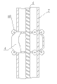
Fig. 2 is the track sectional view of the utility model;
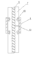
Fig. 3 is the gravity dolly sectional view of the utility model.
Among the figure: 1-fixed gear ring, 2-moving gear, 3-overrunning clutch, 4-gravity locomotive, 5-spiral shaft, 7-track, 9-bearing, 10-pulley, 12-drive link, 13-damping spring, 14-wheel hub.
Embodiment
Below in conjunction with accompanying drawing and embodiment the utility model is described further, only limits to following embodiment but should not be construed the above-mentioned subject area of the utility model.Under the situation that does not break away from the above-mentioned technological thought of the utility model, according to ordinary skill knowledge and customary means, make various replacements and change, all should be included in the utility model scope.
Referring to accompanying drawing: a kind of orientation of orbit slewing gear among the figure comprises fixed gear ring 1, gravity locomotive 4 and wheel hub 14.Said wheel hub 14 is installed on the bearing 9 and is concentric with said fixed gear ring 1, on wheel hub 14, is fixing to be no less than 6 tracks 7 with being spoke shpae.Each bar track 7 has two slide rails that are parallel to each other, and has spiral chute through the spiral shaft 5 of bearing fixing between said slide rail; The end that said spiral shaft 5 points to fixed gear ring 1 is connected with moving gear 2 through overrunning clutch 3, said moving gear 2 and fixed gear ring 1 engagement.Said gravity locomotive 4 slides on the slide rail of track 7 through the pulley 4 that is no less than two pairs, and said spiral shaft 5 inserts the drive link 12 that spiral chute, the other end be fixed on the gravity locomotive 4 through an end and drives.During use, wheel hub rotates, and when gravity dolly 4 moves to the wheel hub top, moves down, and drive link 12 drives spiral shaft 5 rotations, and then drives moving gear 2 rotations, makes potential energy be converted into kinetic energy.
Further, has damping spring 13 between said gravity locomotive 4 and the moving gear 2.On the one hand, spring has played buffer function, prevents the destruction of gravity dolly to device; On the other hand, spring can store a part of potential energy, and then mild release, further, between each dolly spring is installed.
Among the embodiment, said wheel hub 14 connects transmission shaft.Can kinetic energy be exported through transmission shaft, connect the generator even load, produce or test.
Claims (3)
1. orientation of orbit slewing gear is characterized in that: comprise fixed gear ring (1), gravity locomotive (4) and wheel hub (14),
It is last and concentric with said fixed gear ring (1) that said wheel hub (14) is installed in bearing (9), on wheel hub (14), fixing to be no less than 6 tracks (7) with being spoke shpae;
Each bar track (7) has two slide rails that are parallel to each other, and has spiral chute through the spiral shaft (5) of bearing fixing between said slide rail; The end that said spiral shaft (5) points to fixed gear ring (1) is connected with moving gear (2) through overrunning clutch (3), said moving gear (2) and fixed gear ring (1) engagement;
Said gravity locomotive (4) slides on the slide rail of track (7) through the pulley (10) that is no less than two pairs, and said spiral shaft (5) inserts the drive link (12) that spiral chute, the other end be fixed on the gravity locomotive (4) through an end and drives.
2. a kind of orientation of orbit slewing gear according to claim 1 is characterized in that: have damping spring (13) between said gravity locomotive (4) and the moving gear (2).
3. a kind of orientation of orbit slewing gear according to claim 1 is characterized in that: said wheel hub (14) connects transmission shaft.
Priority Applications (1)
| Application Number | Priority Date | Filing Date | Title |
|---|---|---|---|
| CN2011205618661U CN202417841U (en) | 2011-12-29 | 2011-12-29 | Directional rotating device of track |
Applications Claiming Priority (1)
| Application Number | Priority Date | Filing Date | Title |
|---|---|---|---|
| CN2011205618661U CN202417841U (en) | 2011-12-29 | 2011-12-29 | Directional rotating device of track |
Publications (1)
| Publication Number | Publication Date |
|---|---|
| CN202417841U true CN202417841U (en) | 2012-09-05 |
Family
ID=46742612
Family Applications (1)
| Application Number | Title | Priority Date | Filing Date |
|---|---|---|---|
| CN2011205618661U Expired - Fee Related CN202417841U (en) | 2011-12-29 | 2011-12-29 | Directional rotating device of track |
Country Status (1)
| Country | Link |
|---|---|
| CN (1) | CN202417841U (en) |
-
2011
- 2011-12-29 CN CN2011205618661U patent/CN202417841U/en not_active Expired - Fee Related
Similar Documents
| Publication | Publication Date | Title |
|---|---|---|
| CN104863810B (en) | Wheel Rail Vibration generates electricity and energy-storage system | |
| CN201236776Y (en) | Rack type shock-absorbing power generation apparatus | |
| US20140145451A1 (en) | Counterweight powered gravity electrical generation | |
| CN203779520U (en) | Joint speed reducer of industrial robot | |
| CN202417841U (en) | Directional rotating device of track | |
| EP3012451B1 (en) | Kinetic energy collector mechanism to generate electric power from passing vehicles, using a main axle connected to a flywheel | |
| CN104500321B (en) | Wave energy differential linear electric generator | |
| WO2010069450A3 (en) | Stationary energy conversion plant having a device for damping mechanical vibrations | |
| PT106123A (en) | ELECTROMECHANICAL SYSTEM OF GENERATION AND STORAGE OF ELECTRIC ENERGY FROM THE MOVEMENT OF A SURFACE | |
| CN103306909B (en) | Series connection monomer-type energy-storage box in large-scale spiral spring energy storage device | |
| CN102128146A (en) | Gravity kinetic energy power generation device | |
| CN205744316U (en) | A kind of clockwork spring is collected kinetic energy and is driven the device of electromotor converting electrical energy | |
| CN103835892A (en) | Transmission structure for wind driven generator | |
| CN102305197B (en) | Elastic power generator | |
| CN111313606A (en) | A heavy-duty railway track vibration energy harvesting device based on space X-shaped mechanism | |
| CN105141178B (en) | Railway operation remotely monitors elastic deformation energy storage piezoelectricity deformation mass-energy conversion equipment | |
| CN202636133U (en) | Base plate transmission device for movable compact shelf | |
| CN201388148Y (en) | Lever generator | |
| CN104481796B (en) | A kind of linkage turning lifting formula power power generating device by conversion | |
| TW201525283A (en) | Circulating power plant | |
| CN201705600U (en) | Lever machine | |
| CN103147938B (en) | Gravity power increasing gear and vehicle gravity power generation device using gravity power increasing gear | |
| CN202636132U (en) | Operating crank transmission mechanism of mobile compact shelf | |
| CN204716477U (en) | Wheel Rail Vibration generating and energy-storage system | |
| CN202990981U (en) | Direct-drive-type belt pumping unit |
Legal Events
| Date | Code | Title | Description |
|---|---|---|---|
| C14 | Grant of patent or utility model | ||
| GR01 | Patent grant | ||
| C17 | Cessation of patent right | ||
| CF01 | Termination of patent right due to non-payment of annual fee |
Granted publication date: 20120905 Termination date: 20131229 |