CN202412414U - Single-shaft vacuum pug mill - Google Patents
Single-shaft vacuum pug mill Download PDFInfo
- Publication number
- CN202412414U CN202412414U CN2011204886757U CN201120488675U CN202412414U CN 202412414 U CN202412414 U CN 202412414U CN 2011204886757 U CN2011204886757 U CN 2011204886757U CN 201120488675 U CN201120488675 U CN 201120488675U CN 202412414 U CN202412414 U CN 202412414U
- Authority
- CN
- China
- Prior art keywords
- pug
- chamber
- vacuum
- propelling
- pugging
- Prior art date
- Legal status (The legal status is an assumption and is not a legal conclusion. Google has not performed a legal analysis and makes no representation as to the accuracy of the status listed.)
- Expired - Fee Related
Links
Images

Landscapes
- Mixers With Rotating Receptacles And Mixers With Vibration Mechanisms (AREA)
- Mixers Of The Rotary Stirring Type (AREA)
Abstract
The utility mode relates to a single-shaft vacuum pug mill, which comprises a framework. A pug chamber and a pug stirring shaft are arranged on the framework, the pug chamber consists of a primary pug chamber, a pug propelling chamber, a vacuum pug chamber and a discharging chamber which are sequentially adjacently connected to each other from front to back, the primary pug chamber is provided with a feed inlet, the pug stirring shaft is coaxially disposed in the pug chamber, the front end of the pug stirring shaft is in transmission connection with a driving device, the pug stirring shaft consists of a primary pug stirring section, a propelling cutting section, a vacuum pug stirring section and an outlet cutting section, the primary pug stirring section is correspondingly positioned in the primary pug chamber, the propelling cutting section is correspondingly positioned in the pug propelling chamber, the vacuum pug stirring section is correspondingly positioned in the vacuum pug chamber, the outlet cutting section is correspondingly positioned in the discharging chamber, propelling blades are arranged on the propelling cutting section and are conical spiral blades with large front portions and small rear portions, the shape of the pug propelling chamber matches with the appearance of the propelling cutting section, and straight spiral blades are disposed on the outlet cutting section. The single-shaft vacuum pug mill solves problems that an existing vacuum pug mill is poor in pug mixing property and moisture in pug is difficult to be uniformly mixed.
Description
Technical field
The utility model relates to vacuum deairing machine, especially a kind of single shaft vacuum deairing machine.
Background technology
Vacuum deairing machine is a visual plant of producing domestic ceramics and electrotechnical porcelain product; Advance the preceding pug moisture error of vacuum deairing machine and have strict requirement; Pug is normally deposited after processing moulded pottery not yet put in a kiln to bake or mud section after thick the white silk, the back extrusion modling of in being added into vacuum deairing machine, stirring during use, mix.But because the resting period of moulded pottery not yet put in a kiln to bake or mud section has difference; Cause the water content in moulded pottery not yet put in a kiln to bake or the mud section different; Make that the soft durometer of moulded pottery not yet put in a kiln to bake or mud section is different, feed in raw material that vacuum deairing machine can not solve the problem of pug moisture uniformity though can carry out hybrid through the operator; Make the situation that can occur local stiff mud piece or local ooze on the identical product of processing by vacuum deairing machine; Destroy the uniformity of product each several part shrinkage factor, caused product cracking, fragmentation easily, reduced product quality.In addition; The pugging chamber of existing vacuum deairing machine mostly includes only vacuum pugging chamber and discharge chamber; And mostly stir mud axle construction for two, so required drive is bigger, needs to be equipped with independent driving arrangement; This makes that then existing vacuum deairing machine cost is high, floor space is big, and is then inapplicable in the occasion of some small lot batch manufactures.
Summary of the invention
The purpose of the utility model is to provide a kind of single shaft vacuum deairing machine, to solve the problem that existing vacuum deairing machine is poor to the pug Combination, be difficult to make the moisture in the pug to mix.
In order to address the above problem; The single shaft vacuum deairing machine of the utility model adopts following technical scheme: the single shaft vacuum deairing machine; Comprise frame; Said frame is provided with the pugging chamber and stirs the mud axle, and said pugging chamber comprises in the past backward elementary pugging chamber, pug promotion room, vacuum pugging chamber and the discharge chamber of adjacency successively, and said elementary pugging chamber has charging aperture; The said mud axle that stirs has one and indoor with being located in pugging; Stir the mud axle and be connected with drive unit through front end, stir the mud axle and comprise that correspondence is positioned at the indoor elementary propelling segment of cutting that stirs the mud section, is positioned at said pug promotion room of said elementary pugging, is positioned at the outlet segment of cutting that the indoor vacuum of said vacuum pugging is stirred the mud section and is positioned at said discharge chamber, said elementary mud section and the vacuum of stirring stirred the mud section and is provided with reamer; Described propelling segment of cutting is provided with the propelling blade; Said propelling blade is pre-large post-small cone spiral vane, and the profile of the shape of said pug promotion room and said propelling segment of cutting is adaptive, and described outlet segment of cutting is provided with straight helical blade.
The separated web plate that is provided with between said pug promotion room and the vacuum pugging chamber.
Said elementary mud section and the vacuum of stirring stirred to be equipped with on the mud section and played the mud rod.
Said vacuum pugging chamber has observation window, and said observation window place is provided with illuminating lamp.
Because described single shaft vacuum deairing machine is provided with said elementary pugging chamber and pug promotion room before in its vacuum pugging chamber; The said mud axle that stirs comprises that correspondence is positioned at the indoor elementary propelling segment of cutting that stirs the mud section, is positioned at said pug promotion room of said elementary pugging, is positioned at the outlet segment of cutting that the indoor vacuum of said vacuum pugging is stirred the mud section and is positioned at said discharge chamber; Said elementary mud section and the vacuum of stirring stirred the mud section and is provided with the reamer that radially overhangs; Described propelling segment of cutting is provided with the propelling blade of taper, and described outlet segment of cutting is provided with straight helical blade; Therefore; In the course of the work; Pug to be processed at first is added into the pugging chamber through said charging aperture; Pass through said elementary pugging chamber, pug promotion room, vacuum pugging chamber and discharge chamber then successively, thereby make pug, further pushed and rub white silk by the helical blade in the pug promotion room getting into the vacuum pugging chamber before by the indoor reamer cutting and crushing repeatedly of elementary pugging; And then mixed fully and reach the water content unanimity, solved the problem that existing vacuum deairing machine pug Combination is poor, be difficult to make the moisture in the pug to mix; In addition; Owing to adopt single-shaft configuration; Required power when therefore having reduced work; Can with describedly elementaryly stir the mud section, advance segment of cutting, vacuum is stirred the mud section and the outlet segment of cutting is integrated in same stirring on the mud axle, makes that the structure of vacuum deairing machine is compact more, has also guaranteed the synchronism before and after the equipment in the process.
Description of drawings
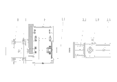
Fig. 1 is the structural representation of single shaft vacuum deairing machine;
Fig. 2 is the vertical view of Fig. 1.
The specific embodiment
The embodiment 1 of single shaft vacuum deairing machine shown in Fig. 1-2, comprises frame 1; Frame 1 is provided with the pugging chamber; The pugging chamber comprises in the past backward elementary pugging chamber 2.1, pug promotion room 2.2, vacuum pugging chamber 2.3 and the discharge chamber 2.4 of adjacency successively, and cylindrical shapes are claimed in wherein elementary pugging chamber 2.1, the top of elementary pugging chamber 2.1 have charging aperture and on said charging aperture button be provided with cover cap 4; During work; Pending pug is added by the charging aperture place on 2.1 tops, elementary pugging chamber, pug promotion room 2.2 be pre-large post-small taper type and and vacuum pugging chamber 2.4 between at a distance from being provided with web plate 3, web plate 3 is used for the pugs that get in the vacuum pugging chamber 2.3 are cut; Thereby make its fully exhaust; The top of vacuum pugging chamber 2.3 has observation window 5 and is provided with illuminating lamp 6 in said observation window 5 places, can observe the indoor working condition of vacuum pugging at any time through observation window 5, so that adjust charging rate in good time; Pugging is indoor coaxially to be provided with one and to stir mud axle 7; Stirring mud axle 7 rotates to be assemblied on the frame and through front end and is connected with drive unit; Drive unit adopts motor 8; Motor 8 and stirring between the mud axle is in transmission connection through a reductor 9, stirs mud axle 7 and comprises that correspondence is positioned at the indoor elementary propelling segment of cutting that stirs the mud section, is positioned at the pug promotion room of elementary pugging, is positioned at the outlet segment of cutting that the indoor vacuum of vacuum pugging is stirred the mud section and is positioned at discharge chamber, and elementary mud section and the vacuum of stirring stirred the mud section and be provided with the reamer 10 that radially overhangs and beat mud excellent 11; Advance segment of cutting to be provided with the propelling blade 12 of taper, the outlet segment of cutting is provided with straight helical blade 13.
During work; Pug is added into the pugging chamber from said charging aperture; Get into said pug promotion room after at first reaching the cutting and crushing repeatedly of playing the mud rod through the indoor reamer of elementary pugging; Pug further also is delivered to the vacuum pugging chamber by the propelling blade cuts in the pug promotion room after getting into the pug promotion room backward, and pug at first passed through described web plate before getting into the vacuum pugging chamber, and pug is cut into fine ribbon through behind the said web plate; Thereby make things convenient for it in the indoor exhaust of vacuum pugging, to reduce gas residual in the pug as far as possible; The indoor pug of entering vacuum pugging is reached by the indoor reamer of vacuum pugging once more plays mud rod cutting and crushing and fully mixing; Straight helical blade in the said discharge chamber of final process once more is cut; Thereby accomplish abundant mixing to pug; During concrete the use, install corresponding ability mould additional in the rear end of discharge chamber according to different needs and can accomplish moulding pug.
Claims (4)
1. single shaft vacuum deairing machine; Comprise frame, said frame is provided with the pugging chamber and stirs the mud axle, it is characterized in that; Said pugging chamber comprises in the past backward elementary pugging chamber, pug promotion room, vacuum pugging chamber and the discharge chamber of adjacency successively; Said elementary pugging chamber has charging aperture, and the said mud axle that stirs has one and indoor with being located in pugging, stirs the mud axle and is connected with drive unit through front end; Stir the mud axle and comprise that correspondence is positioned at the indoor elementary propelling segment of cutting that stirs the mud section, is positioned at said pug promotion room of said elementary pugging, is positioned at the outlet segment of cutting that the indoor vacuum of said vacuum pugging is stirred the mud section and is positioned at said discharge chamber; Said elementary mud section and the vacuum of stirring stirred the mud section and is provided with reamer, and described propelling segment of cutting is provided with the propelling blade, and said propelling blade is pre-large post-small cone spiral vane; The profile of the shape of said pug promotion room and said propelling segment of cutting is adaptive, and described outlet segment of cutting is provided with straight helical blade.
2. single shaft vacuum deairing machine according to claim 1 is characterized in that, the separated web plate that is provided with between said pug promotion room and the vacuum pugging chamber.
3. single shaft vacuum deairing machine according to claim 1 is characterized in that, said elementary mud section and the vacuum of stirring stirred to be equipped with on the mud section and played the mud rod.
4. single shaft vacuum deairing machine according to claim 1 is characterized in that, said vacuum pugging chamber has observation window, and said observation window place is provided with illuminating lamp.
Priority Applications (1)
| Application Number | Priority Date | Filing Date | Title |
|---|---|---|---|
| CN2011204886757U CN202412414U (en) | 2011-11-30 | 2011-11-30 | Single-shaft vacuum pug mill |
Applications Claiming Priority (1)
| Application Number | Priority Date | Filing Date | Title |
|---|---|---|---|
| CN2011204886757U CN202412414U (en) | 2011-11-30 | 2011-11-30 | Single-shaft vacuum pug mill |
Publications (1)
| Publication Number | Publication Date |
|---|---|
| CN202412414U true CN202412414U (en) | 2012-09-05 |
Family
ID=46737206
Family Applications (1)
| Application Number | Title | Priority Date | Filing Date |
|---|---|---|---|
| CN2011204886757U Expired - Fee Related CN202412414U (en) | 2011-11-30 | 2011-11-30 | Single-shaft vacuum pug mill |
Country Status (1)
| Country | Link |
|---|---|
| CN (1) | CN202412414U (en) |
Cited By (1)
| Publication number | Priority date | Publication date | Assignee | Title |
|---|---|---|---|---|
| CN115781913A (en) * | 2023-02-03 | 2023-03-14 | 河北大宾美术用品有限公司 | A convenient and efficient vacuum mud refining machine |
-
2011
- 2011-11-30 CN CN2011204886757U patent/CN202412414U/en not_active Expired - Fee Related
Cited By (1)
| Publication number | Priority date | Publication date | Assignee | Title |
|---|---|---|---|---|
| CN115781913A (en) * | 2023-02-03 | 2023-03-14 | 河北大宾美术用品有限公司 | A convenient and efficient vacuum mud refining machine |
Similar Documents
| Publication | Publication Date | Title |
|---|---|---|
| CN110055792B (en) | Quick recovery and reuse equipment for waste paper | |
| CN204891784U (en) | Vertical high -efficient mixer with many discharging pipes | |
| CN211250759U (en) | Concrete module brick production compounding equipment | |
| CN201913707U (en) | Pug kneading machine | |
| CN202931973U (en) | Extrusion dough mixer | |
| CN202412414U (en) | Single-shaft vacuum pug mill | |
| CN215654758U (en) | Metal powder mixing mechanism | |
| CN111015907A (en) | Production device of straw building blocks | |
| CN107953602B (en) | Stick making machine for charcoal production | |
| CN209736076U (en) | Straw powder and residual film separation equipment | |
| CN204974108U (en) | Device is broken up to saw -dust powder | |
| CN218947985U (en) | Ceramic pug horizontal multi-shaft parallel vacuum pug mill | |
| CN105034165B (en) | A kind of vertical two-stage pugging device | |
| CN203792474U (en) | Bipolar vacuum extruder | |
| CN216543956U (en) | Building cement agitating unit | |
| CN215434486U (en) | A raw materials mixing device for processing plastic granules | |
| CN214238793U (en) | Be applied to high-efficient pugging machine of electroceramic preparation | |
| CN214047470U (en) | A high-efficiency konjac refining device | |
| CN204107368U (en) | Dry mixed feed arrangement prepared by medicine | |
| CN206855755U (en) | A kind of construction site mixer | |
| CN203108499U (en) | Air sealer of bamboo powder stirring equipment and stirring equipment | |
| CN220292910U (en) | Noodle extruder | |
| CN220195056U (en) | Batching agitating unit with shredding function | |
| CN219003232U (en) | Raw material mixing and homogenizing device for ceramic production | |
| CN213499982U (en) | Pug mixing arrangement for ceramic machining |
Legal Events
| Date | Code | Title | Description |
|---|---|---|---|
| C14 | Grant of patent or utility model | ||
| GR01 | Patent grant | ||
| C17 | Cessation of patent right | ||
| CF01 | Termination of patent right due to non-payment of annual fee |
Granted publication date: 20120905 Termination date: 20131130 |