CN202405714U - Anti-swirl lifting support - Google Patents
Anti-swirl lifting support Download PDFInfo
- Publication number
- CN202405714U CN202405714U CN2011203982723U CN201120398272U CN202405714U CN 202405714 U CN202405714 U CN 202405714U CN 2011203982723 U CN2011203982723 U CN 2011203982723U CN 201120398272 U CN201120398272 U CN 201120398272U CN 202405714 U CN202405714 U CN 202405714U
- Authority
- CN
- China
- Prior art keywords
- cross
- arm
- arms
- suspension rod
- eddy current
- Prior art date
- Legal status (The legal status is an assumption and is not a legal conclusion. Google has not performed a legal analysis and makes no representation as to the accuracy of the status listed.)
- Expired - Fee Related
Links
Images
Abstract
The utility model relates to an auxiliary tool of a power supply bus system, concretely to an anti-swirl lifting support. The anti-swirl lifting support comprises suspension rods, cross-arms and insulators; the cross-arms are provided with the insulators; upper and lower end faces of the cross-arms are provided with installing holes; the suspension rods traverse the installing holes and are connected to the cross-arms through upper and lower nuts; insulating tubes are arranged between the installing holes of the cross-arms and the suspension rods; table mats and insulation pads are provided between the nuts and the cross-arms. According to the above structure, the cross-arms and the suspension rods are in insulation connection, which can avoid forming a return circuit with a building grounding system, and thereby can avoid the problems of energy loss and the heating of a suspension bracket and guarantee the reliable operation of a power transmission bus.
Description
Technical field
The utility model relates to the aid of a kind of power supply buses system, specifically a kind of anti-eddy current hoisting bracket.
Background technology
The hoisting bracket of common transmission of electricity bus plays the effect of support and hanging device in project installation equipment.But when lifting is when transmitting the bus equipment of AC energy; Because common hoisting bracket all is that ferrous material is processed; Form the loop between capital and the grounding system; The alternating magnetic field that the A of lifting, B, C phase bus produce makes has eddy current to produce on the hoisting bracket, the eddy current of formation not only can cause the loss of energy but also can cause the suspension bracket heating, can influence the normal power transmission and distribution of A, B, C phase bus when serious.
Summary of the invention
The technical problem that the utility model will solve provides a kind of eddy current that can prevent and produces, and guarantees the anti-eddy current hoisting bracket of normal power transmission and distribution.
In order to solve the problems of the technologies described above, the anti-eddy current hoisting bracket of the utility model comprises suspension rod, cross-arm and insulator, and cross-arm is provided with insulator; Place, cross-arm upper and lower end face is provided with installing hole; Suspension rod passes installing hole and is connected on the cross-arm through nut up and down; Be provided with insulated tube between the installing hole of cross-arm and the suspension rod, be lined with bowl pad and insulation spacer between nut and the cross-arm, make mutually insulated between suspension rod and the cross-arm.
Said suspension rod is set to more than two and is set in parallel on the cross-arm, and said insulator is arranged between the suspension rod.
Said cross-arm is a channel-section steel.
After adopting above-mentioned structure; Since between cross-arm and the suspension rod insulation is connected prevent having avoided and the grounding system of building between form the loop; Thereby the eddy current of having avoided producing between suspension rod and the cross-arm causes the loss and the suspension bracket heating problem of energy, has guaranteed the reliability service of transmission of electricity bus.
Description of drawings
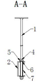
Fig. 1 is the anti-eddy current hoisting bracket front view of the utility model;
Fig. 2 is the anti-eddy current hoisting bracket A-A view of the utility model.
Embodiment
Below in conjunction with accompanying drawing and embodiment, the anti-eddy current hoisting bracket of the utility model is done further explain.
As shown in the figure, the anti-eddy current hoisting bracket of the utility model comprises suspension rod 1, cross-arm 2 and insulator 3, and cross-arm 2 is a channel-section steel; Adopt suspension rod and the channel-section steel main material as the anti-eddy current hoisting bracket of the utility model, its middle hanger is as supporting suspension centre, and channel-section steel is as cross-arm.Said cross-arm 2 is arranged on the bottom of suspension rod 1, and cross-arm 2 is provided with insulator 3; Place, cross-arm 2 upper and lower end faces is provided with installing hole, and suspension rod 1 passes installing hole and is connected on the cross-arm 2 through last lower nut 4, is provided with insulated tube 7 between cross-arm 2 and the suspension rod 1, contacts with cross-arm 2 to prevent suspension rod 1; Avoided and the grounding system of building between form closed magnetic circuit, also be provided with a bowl pad 5 and an insulation spacer 6 between said nut 4 and the cross-arm 2, contact with channel-section steel through the nut suspension rod preventing.
Above-mentioned suspension rod 1 is set to more than two and is set in parallel on the cross-arm 2, and said insulator 3 is arranged between the suspension rod 1.What install on the insulator in the illustrated embodiment on the anti-eddy current hoisting bracket cross-arm is A, B, C, the N bus of transmitting electricity mutually.
Claims (3)
1. an anti-eddy current hoisting bracket comprises suspension rod (1), cross-arm (2) and insulator (3), and it is characterized in that: cross-arm (2) is provided with insulator (3); Place, cross-arm (2) upper and lower end face is provided with installing hole; Suspension rod (1) passes installing hole and is connected on the cross-arm (2) through last lower nut (4); Be provided with insulated tube (7) between the installing hole of cross-arm (2) and the suspension rod (1), be lined with bowl pad (5) and insulation spacer (6) between said nut (4) and the cross-arm (2).
2. according to the described anti-eddy current hoisting bracket of claim 1, it is characterized in that: said suspension rod (1) is set to more than two and is set in parallel on the cross-arm (2), and said insulator (3) is arranged between the suspension rod (1).
3. according to claim 1 or 2 described anti-eddy current hoisting brackets, it is characterized in that: said cross-arm (2) is a channel-section steel.
Priority Applications (1)
| Application Number | Priority Date | Filing Date | Title |
|---|---|---|---|
| CN2011203982723U CN202405714U (en) | 2011-10-19 | 2011-10-19 | Anti-swirl lifting support |
Applications Claiming Priority (1)
| Application Number | Priority Date | Filing Date | Title |
|---|---|---|---|
| CN2011203982723U CN202405714U (en) | 2011-10-19 | 2011-10-19 | Anti-swirl lifting support |
Publications (1)
| Publication Number | Publication Date |
|---|---|
| CN202405714U true CN202405714U (en) | 2012-08-29 |
Family
ID=46703331
Family Applications (1)
| Application Number | Title | Priority Date | Filing Date |
|---|---|---|---|
| CN2011203982723U Expired - Fee Related CN202405714U (en) | 2011-10-19 | 2011-10-19 | Anti-swirl lifting support |
Country Status (1)
| Country | Link |
|---|---|
| CN (1) | CN202405714U (en) |
Cited By (3)
| Publication number | Priority date | Publication date | Assignee | Title |
|---|---|---|---|---|
| CN106410718A (en) * | 2016-11-01 | 2017-02-15 | 金螳螂精装科技(苏州)有限公司 | Construction site temporary power supply erecting system |
| CN106764048A (en) * | 2016-11-23 | 2017-05-31 | 中国冶集团有限公司 | The method that airduct installation is carried out using self-locking type wind pipe suspension bracket |
| CN109217213A (en) * | 2017-06-29 | 2019-01-15 | 河南平高电气股份有限公司 | A kind of busbar supporting device and the bus transmission system using the support device |
-
2011
- 2011-10-19 CN CN2011203982723U patent/CN202405714U/en not_active Expired - Fee Related
Cited By (4)
| Publication number | Priority date | Publication date | Assignee | Title |
|---|---|---|---|---|
| CN106410718A (en) * | 2016-11-01 | 2017-02-15 | 金螳螂精装科技(苏州)有限公司 | Construction site temporary power supply erecting system |
| CN106764048A (en) * | 2016-11-23 | 2017-05-31 | 中国冶集团有限公司 | The method that airduct installation is carried out using self-locking type wind pipe suspension bracket |
| CN106764048B (en) * | 2016-11-23 | 2018-10-23 | 中国一冶集团有限公司 | The method that air hose installation is carried out using self-locking type wind pipe hanger |
| CN109217213A (en) * | 2017-06-29 | 2019-01-15 | 河南平高电气股份有限公司 | A kind of busbar supporting device and the bus transmission system using the support device |
Similar Documents
| Publication | Publication Date | Title |
|---|---|---|
| CN202405714U (en) | Anti-swirl lifting support | |
| CN102403674B (en) | A kind of live-wire work insulating cross arm | |
| CN202260256U (en) | Insulated wire drainage bracket | |
| CN202997461U (en) | Tubular busbar specially for power supply for high-rise building floor | |
| CN206441991U (en) | A kind of electric pole lightning protection device | |
| CN202384715U (en) | High voltage insulated wire holder | |
| CN204332890U (en) | With the fuse switch of electricity-detection grounding device | |
| CN203883146U (en) | Anti-disengagement type ground wire pile easy to suspend | |
| CN203734251U (en) | Three-phase common box bus used for 252kV high-voltage switch | |
| CN203787582U (en) | Quick cable connection strip used between high-voltage frequency converter cabinets | |
| CN206379626U (en) | A kind of intermediate switchgear cabinet insulation contact box | |
| CN206516982U (en) | Insulation lead wire support closing hook | |
| CN206976984U (en) | A kind of cable anchor ear component of box type transformer low-pressure side | |
| CN207249391U (en) | Can remote detection electric pole | |
| CN102931020B (en) | Insulator crossarm isolating switch | |
| CN206421893U (en) | Transformer New Low Voltage winding leading-out wire structure | |
| CN203812795U (en) | Plateau high-voltage load switch-fuse composite electric appliance | |
| CN202564888U (en) | High tension cable installation seat | |
| CN204517170U (en) | Outdoor vacuum switch insulating support | |
| CN204088911U (en) | A kind of insulation installation structure for switch cubicle | |
| CN204376274U (en) | A kind of fixture of charged for replacement 10kV outdoor disconnecting link | |
| CN204205296U (en) | A kind of trapezoid support electrical power wiring row | |
| CN103532063A (en) | High-voltage sharing-box bus duct system | |
| CN204045942U (en) | A kind of mounting structure of induction furnace water-cooled Electric heating capacitance group | |
| CN204012186U (en) | A kind of Novel lightning-proof device based on burning exoergic technology |
Legal Events
| Date | Code | Title | Description |
|---|---|---|---|
| C14 | Grant of patent or utility model | ||
| GR01 | Patent grant | ||
| CF01 | Termination of patent right due to non-payment of annual fee |
Granted publication date: 20120829 Termination date: 20141019 |
|
| EXPY | Termination of patent right or utility model |