CN202399879U - Engine auxiliary support device for light-duty truck - Google Patents
Engine auxiliary support device for light-duty truck Download PDFInfo
- Publication number
- CN202399879U CN202399879U CN2011204795921U CN201120479592U CN202399879U CN 202399879 U CN202399879 U CN 202399879U CN 2011204795921 U CN2011204795921 U CN 2011204795921U CN 201120479592 U CN201120479592 U CN 201120479592U CN 202399879 U CN202399879 U CN 202399879U
- Authority
- CN
- China
- Prior art keywords
- support assembly
- assembly
- engine
- left socle
- cross beam
- Prior art date
- Legal status (The legal status is an assumption and is not a legal conclusion. Google has not performed a legal analysis and makes no representation as to the accuracy of the status listed.)
- Expired - Lifetime
Links
Images


Abstract
An engine auxiliary support device for a light-duty truck is characterized in that a left support assembly consists of a left support plate and two reinforcement plates by means of soldermask, and a right support assembly is symmetrical to the left support assembly. A supporting crossbeam is made into a channel beam by a steel plate, an engine and a transmission are integrally assembled and then the left support assembly and the right support assembly are mounted on two sides of a transmission box through bolts respectively. The left support assembly and the right support assembly are further connected with the supporting crossbeam through bolts respectively, two ends of the supporting crossbeam are connected with an upper wing face of a frame left longitudinal beam and an upper wing face of a frame right longitudinal beam respectively, and buffering rubber cushions are arranged at the joints. After the engine auxiliary support device is mounted on the light-duty truck, load borne by a front supporting device and a rear supporting device of an engine can be greatly reduced, utilization reliability of the truck is greatly improved, and service lives of relevant supporting parts of the engine are greatly prolonged. Further, the buffering rubber cushions have better elasticity, so that vibration in operation of the engine can be lessened, and the problem of over-location of the engine auxiliary support device can be solved.
Description
Technical field
The utility model relates to bearing device for automobile engine, particularly a kind of light truck driving engine secondary support means.
Background technology
Bearing device for automobile engine not only will bear the weight of driving engine, but also will bear the counter-force that driving engine is exported to the car transmissions moment of torsion.The support pattern of light truck driving engine is generally at present: 1, engine front support device through rubber buffer, is bearing in vehicle frame left and right longeron inboard with front of the engine on left and right both sides, engine cylinder-body bottom.2, bearing set behind the driving engine is bearing in vehicle frame left and right longeron inboard with the driving engine rear end through rubber buffer on the left and right both sides of flywheel shell of engine.Along with the diesel oil degree of light truck driving engine is increasingly high, and reinforcing degree is also increasingly high, and particularly the use of exhaust turbocharging device is more and more general, and the weight and the moment of torsion of driving engine are increasing.And the parameter of used change-speed box is more and more advanced, and weight is also increasing.Cause the left and right longeron distortion of vehicle frame of the forward and backward bearing set of used driving engine installation site; The tenesmus of the forward and backward supporting mass assembly of driving engine occurrence positions; The car transmissions correlation parameter changes; Cause driving system associated components noise and wearing and tearing to strengthen, it is comparatively general that the forward and backward bearing set rubber buffer of driving engine damages phenomenon.Sometimes even the phenomenon that fracture takes place the forward and backward supporting mass assembly of driving engine occurs.Medium-sized and heavy-duty truck has generally all adopted the driving engine secondary support means at present; At the change-speed box top force transferring part that corresponding support is used as the driving engine secondary support means is installed; Yet the light truck transmission dimensions is less; The transmission case cover at its top is comparatively thin, and gear controller has been installed above it, does not have the suitable installation site of support.Therefore, the unsuitable driving engine secondary support means structure that adopts in-between car of light truck.
Summary of the invention
The utility model proposes a kind of light truck driving engine secondary support means, and it can make the problems referred to above greatly improved.
This light truck driving engine secondary support means that the utility model provides; Form by left socle assembly, right support assembly and bearing cross beam; It is characterized in that the left socle assembly is formed right support assembly and left socle assembly symmetry by left socle plate and the weldering of two reinforcement plate resistances; Bearing cross beam is made into channel-section rail with steel plate, and its base punching press has slotted hole; Driving engine and change-speed box are assembled into one behind the part, and left socle assembly and right support assembly are installed in the mission case both sides through bolt respectively; Left socle assembly and right support assembly also are connected with bearing cross beam respectively through bolt, and the bearing cross beam two ends are connected with the left and right longeron top airfoil of vehicle frame respectively through bolt.
There is cushion rubber bumper at connection location place between said left socle assembly and right support assembly and the bearing cross beam, and there is cushion rubber bumper at the connection location place between the left and right longeron of said bearing cross beam and vehicle frame.
After light truck installs this driving engine secondary support means that the utility model provides additional; Alleviate the load that the forward and backward bearing set of driving engine bears greatly, obtained very big lifting the service life of car opertion reliability and engine mounting associated components.Cushion compound is lined with elasticity preferably, the vibration in the time of not only can slowing down engine operation, and can solve the mistake orientation problem of driving engine secondary support means; This device can be widely used in light truck.
Description of drawings
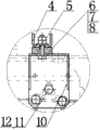
Fig. 1 is the overall structure scheme drawing of the utility model.
Fig. 2 is the partial enlarged view of I among Fig. 1.
Fig. 3 is the A-A cutaway view of Fig. 1.
Fig. 4 is the partial enlarged view of II among Fig. 3.
Fig. 5 is the front view of left socle assembly structure.
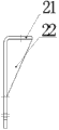
Fig. 6 is the left view of left socle assembly structure.
Fig. 7 is the birds-eye view of left socle assembly structure.
Fig. 8 is the birds-eye view of Fig. 6.
The specific embodiment
Be elaborated below in conjunction with accompanying drawing.
Like Fig. 1, shown in Figure 2, need mounted component change-speed box 3 and this Unit Installation matrix: vehicle frame left side longeron 1 is represented with vehicle frame right vertical beam 13 usefulness long and two-short dash linees, does transparence and handles.This light truck driving engine secondary support means, major part is: left socle assembly 2, right support assembly 10, bearing cross beam 4.Left socle assembly 2 is formed by left socle plate and two brace panel assembly weldings, right support assembly 10 and left socle assembly 2 symmetries; Bearing cross beam 4 usefulness steel plates are made into channel-section rail, and its base punching press has four slotted holes.The change-speed box 3 casing both sides of driving engine rear end are processed with three tapped bore respectively; Driving engine and change-speed box 3 are assembled into one behind the part; Through the special bolt 11 in these six tapped bore that are installed in change-speed box 3 casing both sides, φ 12 spring washers 12, respectively left socle assembly 2 and right support assembly 10 are installed in change-speed box 3 casing both sides.Place first cushion rubber bumper 5 respectively at left socle assembly 2 and above the right support assembly 10, and connect at the bearing cross beam middle part., bearing cross beam 4 two ends are installed in after filling up one second cushion rubber bumper 9 respectively on vehicle frame left side longeron 1, vehicle frame right vertical beam 10 top airfoils; Use a M12 * 80 bolts 6 to pass the slotted hole at vehicle frame left side longeron 1 bolt hole, vehicle frame right vertical beam 10 bolts hole, second cushion rubber bumper 9 and bearing cross beam 4 two ends respectively; Large washer 7 back installing M 12 nuts 8 on the pad; After tightening M12 nut 8, a same nut is installed is again become flexible preventing.Cushion compound is lined with elasticity preferably, the vibration in the time of not only can slowing down engine operation, and can solve the mistake orientation problem of driving engine secondary support means.After light truck installs this driving engine secondary support means additional, alleviate the load that the forward and backward bearing set of driving engine bears greatly, obtained very big lifting the service life of car opertion reliability and engine mounting associated components.This device can be widely used in light truck.
Like Fig. 3, shown in Figure 4; The change-speed box 3 casing right sides of driving engine rear end are processed with three tapped bore; Driving engine and change-speed box 3 are assembled into one behind the part; Through the special bolt 11 in three tapped bore that are installed in change-speed box 3 casing right sides, φ 12 spring washers 12, right support assembly 10 is installed in change-speed box 3 casing right sides.On right support assembly 10, place cushion rubber bumper; Pass the slotted hole of keeping right in right support assembly 10 top slotted holes, cushion rubber bumper 5 and bearing cross beam 4 middle parts with a M12 * 80 bolts 6; Large washer 7 back installing M 12 nuts 8 on the pad are tightened back M12 nut 8 and a same nut is installed is again become flexible preventing.
As shown in Figure 5, bearing cross beam 4 usefulness steel plates are made into channel-section rail, and its base punching press has slotted hole.Be installed on longeron 1 top airfoil of a vehicle frame left side behind a cushion rubber bumper 9 on the bearing cross beam 4 left end pads; Pass the slotted hole of vehicle frame left side longeron 1 bolt hole, cushion rubber bumper 9 and bearing cross beam 4 left ends with a M12 * 80 bolts 6; Large washer 7 back installing M 12 nuts 8 on the pad; After tightening M12 nut 8, a same nut is installed is again become flexible preventing.
As shown in Figure 6, the left socle assembly is formed by left socle plate made from steel plate 21 and two brace panels, the 22 resistance welderings made from steel plate equally.Left socle plate 21 is bent into the right angle, and its top margin punching press has a slotted hole, and the stile punching press has three bolt mounting holes.
As shown in Figure 7, the left socle assembly is formed by left socle plate made from steel plate 21 and two brace panels, the 22 resistance welderings made from steel plate equally.Brace panel 22 blanking triangularities.
As shown in Figure 8, left socle plate 21 usefulness steel plates are bent into the right angle, and its top margin punching press has a slotted hole.
Claims (2)
1. a light truck driving engine secondary support means is made up of left socle assembly, right support assembly and bearing cross beam, it is characterized in that the left socle assembly is formed right support assembly and left socle assembly symmetry by left socle plate and the weldering of two reinforcement plate resistances; Bearing cross beam is made into channel-section rail with steel plate, and driving engine and change-speed box are assembled into one behind the part, and left socle assembly and right support assembly are installed in the mission case both sides through bolt respectively; Left socle assembly and right support assembly also are connected with bearing cross beam respectively through bolt, and the bearing cross beam two ends are connected with the left and right longeron top airfoil of vehicle frame respectively through bolt.
2. light truck driving engine secondary support means as claimed in claim 1; It is characterized in that: there is cushion rubber bumper at the connection location place between said left socle assembly and right support assembly and the bearing cross beam, and there is cushion rubber bumper at the connection location place between the left and right longeron of said bearing cross beam and vehicle frame.
Priority Applications (1)
| Application Number | Priority Date | Filing Date | Title |
|---|---|---|---|
| CN2011204795921U CN202399879U (en) | 2011-11-28 | 2011-11-28 | Engine auxiliary support device for light-duty truck |
Applications Claiming Priority (1)
| Application Number | Priority Date | Filing Date | Title |
|---|---|---|---|
| CN2011204795921U CN202399879U (en) | 2011-11-28 | 2011-11-28 | Engine auxiliary support device for light-duty truck |
Publications (1)
| Publication Number | Publication Date |
|---|---|
| CN202399879U true CN202399879U (en) | 2012-08-29 |
Family
ID=46697549
Family Applications (1)
| Application Number | Title | Priority Date | Filing Date |
|---|---|---|---|
| CN2011204795921U Expired - Lifetime CN202399879U (en) | 2011-11-28 | 2011-11-28 | Engine auxiliary support device for light-duty truck |
Country Status (1)
| Country | Link |
|---|---|
| CN (1) | CN202399879U (en) |
Cited By (2)
| Publication number | Priority date | Publication date | Assignee | Title |
|---|---|---|---|---|
| CN106143098A (en) * | 2015-05-15 | 2016-11-23 | 通用汽车环球科技运作有限责任公司 | Electromotor mounting assembly |
| CN106627086A (en) * | 2015-11-04 | 2017-05-10 | 云南力帆骏马车辆有限公司 | Light truck engine rear bearing device |
-
2011
- 2011-11-28 CN CN2011204795921U patent/CN202399879U/en not_active Expired - Lifetime
Cited By (4)
| Publication number | Priority date | Publication date | Assignee | Title |
|---|---|---|---|---|
| CN106143098A (en) * | 2015-05-15 | 2016-11-23 | 通用汽车环球科技运作有限责任公司 | Electromotor mounting assembly |
| CN106143098B (en) * | 2015-05-15 | 2019-06-07 | 通用汽车环球科技运作有限责任公司 | Engine mounting assembly |
| CN106627086A (en) * | 2015-11-04 | 2017-05-10 | 云南力帆骏马车辆有限公司 | Light truck engine rear bearing device |
| CN106627086B (en) * | 2015-11-04 | 2019-08-13 | 云南力帆骏马车辆有限公司 | A kind of light truck engine rear support device |
Similar Documents
| Publication | Publication Date | Title |
|---|---|---|
| CN201800521U (en) | Front suspended cushion assembly for engine of heavy truck | |
| CN102501751A (en) | Hydraulic suspension cushion assembly of engine | |
| CN201228749Y (en) | Suspension cushion assembly for engine | |
| CN202399879U (en) | Engine auxiliary support device for light-duty truck | |
| CN201818707U (en) | Rear suspension cushion assembly for engine | |
| CN201300707Y (en) | Power assembly suspending system | |
| CN101982330B (en) | Improved front support device of truck engine | |
| CN204340645U (en) | One is card engine front mounting rubber cushion heavily | |
| CN201071894Y (en) | Suspending cushion and car body | |
| CN204774466U (en) | Leaf spring support and leaf spring support mounting structure | |
| CN203402248U (en) | Front auxiliary frame structure of automobile with engine with three suspensions and automobile | |
| CN203766489U (en) | Car radiator supporting system | |
| CN201824861U (en) | Improved truck engine front supporting device | |
| CN201824859U (en) | Auxiliary bearing device for engine of medium-size truck | |
| CN204701659U (en) | A kind of lightweight cargo vehicle frame front end cross beam | |
| CN202208317U (en) | Automobile frame | |
| CN202935454U (en) | Cab fixing structure of mining dump vehicle | |
| CN202557615U (en) | Integrated automobile chassis supporting structure | |
| CN202528832U (en) | Vibration isolator for engine | |
| CN205202710U (en) | Supporting arrangement behind light truck engine | |
| CN204774639U (en) | Gearbox side mounting structure | |
| CN201980079U (en) | Gearbox suspension soft mat assembly | |
| CN201753001U (en) | Control arm support | |
| CN219565233U (en) | Fourth cross beam assembly of automobile | |
| CN204037313U (en) | A kind of COE truck driving engine secondary support means |
Legal Events
| Date | Code | Title | Description |
|---|---|---|---|
| C14 | Grant of patent or utility model | ||
| GR01 | Patent grant | ||
| CX01 | Expiry of patent term |
Granted publication date: 20120829 |
|
| CX01 | Expiry of patent term |