CN202290828U - One-step forming die for gear shaft - Google Patents
One-step forming die for gear shaft Download PDFInfo
- Publication number
- CN202290828U CN202290828U CN2011203537941U CN201120353794U CN202290828U CN 202290828 U CN202290828 U CN 202290828U CN 2011203537941 U CN2011203537941 U CN 2011203537941U CN 201120353794 U CN201120353794 U CN 201120353794U CN 202290828 U CN202290828 U CN 202290828U
- Authority
- CN
- China
- Prior art keywords
- die
- punch
- forming die
- gear
- fixed cover
- Prior art date
- Legal status (The legal status is an assumption and is not a legal conclusion. Google has not performed a legal analysis and makes no representation as to the accuracy of the status listed.)
- Expired - Fee Related
Links
Images

Abstract
The utility model discloses a one-step forming die for a gear shaft, wherein a lower die fixing sleeve is arranged at the lower part of a die frame; a concave die pressing ring is internally provided with a gear forming concave die and a square forming concave die in sequence from top to bottom and is arranged in the lower die fixing sleeve; a convex die is arranged at the upper part of the die frame by a fixing nut, a bush and a convex die fixing sleeve and is coaxial with the gear forming concave die; and an ejector rod used for demoulding of a processed workpiece is arranged at the center of the bottom of the die frame by an adjusting nut. In the utility model, the structures of the convex die and the concave die are optimized, the strength of the convex die and the concave die are improved, and the service life of the die is prolonged; a special die structure is adopted, so that a power transfer square and a tooth form are formed by one step, the requirement on the quality of workpieces is ensured, the production efficiency is improved, and the production cost is lowered; and the one-step forming die is smart in structure and convenient to replace.
Description
Technical field
The utility model relates to the machining mould applications, specifically is a kind of gear shaft one-time forming die.
Background technology
The processing of gear shaft is the difficult point of machining, and the object of processing is the gear teeth face processing difficulties not only, and simultaneously because other part specification requirement of profile of tooth and gear shaft is high, thereby difficulty of processing is big.
The existing processing method that adopts is: the flank of tooth adopts gear-hobbing machine processing, transferring power four directions with milling processing.The shortcoming of this processing mode is: efficient is low; Burr is big, removes the burr difficulty, and product percent of pass is low, and labor content is big.
Summary of the invention
The purpose of the utility model provides a kind of gear shaft one-time forming die, in order to improve above-mentioned technology, specifically realizes through following technical scheme:
A kind of gear shaft one-time forming die, this mould comprise mould bases, counterdie fixed cover, cubic molding concave die, die trim ring, gear forming die, punch, hold-down nut, lining, punch fixed cover, push rod; The counterdie fixed cover is arranged on the mould bases bottom; Gear forming die and cubic molding concave die are housed in the die trim ring from top to bottom successively and are arranged in the counterdie fixed cover; Punch is arranged on mould bases top through hold-down nut, lining and punch fixed cover and punch is coaxial with the gear forming die; Be used for making the push rod of the workpiece demoulding to be arranged on mould bases bottom and coaxial with cubic molding concave die.
Described a kind of gear shaft one-time forming die that has, it further designs and is: also be provided with the adjustment bolt that is used for adjusting gear forming die and punch axiality on the said counterdie fixed cover.
Described a kind of gear shaft one-time forming die that has, it further designs and is: be provided with backing plate between said punch and the mould bases upper end.
The utility model has adopted the mould structure of gear shaft once-forming, and compared with prior art, its advantage is: punch of the utility model and die structure optimization, and the intensity of punch, die is improved, and has prolonged the service life of mould; The utility model has adopted special mould structure, makes transferring power four directions and profile of tooth once-forming, has guaranteed the workpiece quality requirement, has improved production efficiency, has reduced production cost; The utility model structure is ingenious, and it is convenient to change.
Description of drawings
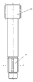
Fig. 1 is the structural representation of the utility model.
Fig. 2 is the said gear shaft structure sketch map of the utility model.
Fig. 3 is an A-A cross sectional view among Fig. 2.
The specific embodiment
Shaping dies as shown in Figure 1 comprises mould bases 1, counterdie fixed cover 2, cubic molding concave die 3, die trim ring 4, gear forming die 5, pressing plate 6, punch 7, hold-down nut 8, lining 9, punch fixed cover 10, backing plate 11 and push rod 12; Counterdie fixed cover 2 is arranged on mould bases 1 bottom; Cubic molding concave die 3 is housed with gear forming die 5 and be fixed in the counterdie fixed cover 2 in the die trim ring 4; Punch 7 is fixed on mould bases 1 top through hold-down nut 8 and punch fixed cover 10, and is positioned at and gear forming die 5 corresponding positions by lining 10; Mould bases 1 bottom central is provided with through hole, and push rod 12 is arranged on mould bases 1 bottom central through a nut and this through hole, is arranged on the mould bases 1 and is positioned at the lower end of cubic molding concave die 3.Also be provided with the adjustment bolt 13 that is used for adjusting gear forming die 5 and punch 7 axialities on the counterdie fixed cover 2.Be provided with between punch 7 and mould bases 1 upper end and be used to the backing plate 11 that guarantees that punch 7 steadily moves down.
During extruding, at first extrusion blank is placed in the gear forming die 5, punch 7 is descending, and extrusion blank is clamp-oned in cubic molding concave die 3 and the gear forming die 5 simultaneously, makes transferring power four directions and gear once-forming.When hold-down nut 8 end faces contacted with die trim ring 4 end faces, punch 7 can not be descending, and extruding finishes.Push rod 12 is up, and workpiece is ejected from die, and map 2 and Fig. 3, the gear parts 15 of gear shaft be in 5 extrusion modlings of gear forming die, the extrusion modling in cubic molding concave die 3 of the cubic part 16 of gear shaft.
Be protection punch 7, adopted guide pillar and guide pin bushing to make guiding four guide pillar mould bases 1.For protection gear forming die 5, on mould structure, taked spacing measure.The utility model punch is changed convenient.The utility model makes transferring power four directions and profile of tooth once-forming, has guaranteed the workpiece quality requirement, has improved production efficiency, has reduced production cost.
Claims (3)
1. gear shaft one-time forming die, it is characterized in that: this mould comprises mould bases (1), counterdie fixed cover (2), cubic molding concave die (3), die trim ring (4), gear forming die (5), punch (7), hold-down nut (8), lining (9), punch fixed cover (10), push rod (12); Counterdie fixed cover (2) is arranged on mould bases (1) bottom; Gear forming die (5) and cubic molding concave die (3) are housed in the die trim ring (4) from top to bottom successively and are arranged in the counterdie fixed cover (2); Punch (7) is arranged on mould bases (1) top through hold-down nut (8), lining (9) and punch fixed cover (10) and punch (7) is coaxial with gear forming die (5); Be used for making the push rod (12) of the workpiece demoulding to be arranged on mould bases (1) bottom and coaxial with cubic molding concave die (3).
2. a kind of gear shaft one-time forming die that has according to claim 1 is characterized in that: also be provided with the adjustment bolt (13) that is used for adjusting gear forming die (5) and punch (7) axiality on the said counterdie fixed cover (2).
3. a kind of gear shaft one-time forming die that has according to claim 1 is characterized in that: be provided with backing plate (11) between said punch (7) and the mould bases (1).
Priority Applications (1)
| Application Number | Priority Date | Filing Date | Title |
|---|---|---|---|
| CN2011203537941U CN202290828U (en) | 2011-09-21 | 2011-09-21 | One-step forming die for gear shaft |
Applications Claiming Priority (1)
| Application Number | Priority Date | Filing Date | Title |
|---|---|---|---|
| CN2011203537941U CN202290828U (en) | 2011-09-21 | 2011-09-21 | One-step forming die for gear shaft |
Publications (1)
| Publication Number | Publication Date |
|---|---|
| CN202290828U true CN202290828U (en) | 2012-07-04 |
Family
ID=46359809
Family Applications (1)
| Application Number | Title | Priority Date | Filing Date |
|---|---|---|---|
| CN2011203537941U Expired - Fee Related CN202290828U (en) | 2011-09-21 | 2011-09-21 | One-step forming die for gear shaft |
Country Status (1)
| Country | Link |
|---|---|
| CN (1) | CN202290828U (en) |
Cited By (11)
| Publication number | Priority date | Publication date | Assignee | Title |
|---|---|---|---|---|
| CN102303059A (en) * | 2011-09-21 | 2012-01-04 | 南京工业职业技术学院 | One-time molding method of gear wheel shaft |
| CN102794327A (en) * | 2012-08-23 | 2012-11-28 | 湖南天雁机械有限责任公司 | Mold for extrusion forming of engine valve rotating mechanism base |
| CN103639292A (en) * | 2013-11-25 | 2014-03-19 | 梧州恒声电子科技有限公司 | Lower die structure of U-iron extrusion die |
| CN103639222A (en) * | 2013-11-25 | 2014-03-19 | 梧州恒声电子科技有限公司 | U iron extrusion die |
| CN103752639A (en) * | 2014-01-26 | 2014-04-30 | 无锡市神力齿轮冷挤有限公司 | Cold extrusion die for output shaft of starter |
| CN104084489A (en) * | 2014-06-26 | 2014-10-08 | 梧州恒声电子科技有限公司 | Die fine adjusting mechanism |
| CN104259237A (en) * | 2014-09-26 | 2015-01-07 | 北京北方车辆集团有限公司 | Hot extrusion die applicable to extrusion and forming of inner hexagonal bolt of track end coupling device |
| CN105834238A (en) * | 2016-05-30 | 2016-08-10 | 南京工业职业技术学院 | Stopper ring molding and shaping mold and stopper ring production method |
| CN107716727A (en) * | 2017-11-29 | 2018-02-23 | 中国航空工业标准件制造有限责任公司 | Punch process supporting plate self-lock nut pallet flute profile shaping mould |
| CN108246962A (en) * | 2017-11-27 | 2018-07-06 | 苏州麦德柯金属制品工业有限公司 | The processing technology and its processing mold of a kind of rivet |
| CN111266430A (en) * | 2018-12-04 | 2020-06-12 | 无锡市华机机械制造有限公司 | Method for forming rotating shaft for pneumatic actuator |
-
2011
- 2011-09-21 CN CN2011203537941U patent/CN202290828U/en not_active Expired - Fee Related
Cited By (13)
| Publication number | Priority date | Publication date | Assignee | Title |
|---|---|---|---|---|
| CN102303059A (en) * | 2011-09-21 | 2012-01-04 | 南京工业职业技术学院 | One-time molding method of gear wheel shaft |
| CN102794327B (en) * | 2012-08-23 | 2016-06-29 | 湖南天雁机械有限责任公司 | Engine valve rotating mechanism base extrusion forming mold |
| CN102794327A (en) * | 2012-08-23 | 2012-11-28 | 湖南天雁机械有限责任公司 | Mold for extrusion forming of engine valve rotating mechanism base |
| CN103639292A (en) * | 2013-11-25 | 2014-03-19 | 梧州恒声电子科技有限公司 | Lower die structure of U-iron extrusion die |
| CN103639222A (en) * | 2013-11-25 | 2014-03-19 | 梧州恒声电子科技有限公司 | U iron extrusion die |
| CN103752639B (en) * | 2014-01-26 | 2016-08-17 | 无锡市神力齿轮冷挤有限公司 | Starter motor output shaft cold extrusion die |
| CN103752639A (en) * | 2014-01-26 | 2014-04-30 | 无锡市神力齿轮冷挤有限公司 | Cold extrusion die for output shaft of starter |
| CN104084489A (en) * | 2014-06-26 | 2014-10-08 | 梧州恒声电子科技有限公司 | Die fine adjusting mechanism |
| CN104259237A (en) * | 2014-09-26 | 2015-01-07 | 北京北方车辆集团有限公司 | Hot extrusion die applicable to extrusion and forming of inner hexagonal bolt of track end coupling device |
| CN105834238A (en) * | 2016-05-30 | 2016-08-10 | 南京工业职业技术学院 | Stopper ring molding and shaping mold and stopper ring production method |
| CN108246962A (en) * | 2017-11-27 | 2018-07-06 | 苏州麦德柯金属制品工业有限公司 | The processing technology and its processing mold of a kind of rivet |
| CN107716727A (en) * | 2017-11-29 | 2018-02-23 | 中国航空工业标准件制造有限责任公司 | Punch process supporting plate self-lock nut pallet flute profile shaping mould |
| CN111266430A (en) * | 2018-12-04 | 2020-06-12 | 无锡市华机机械制造有限公司 | Method for forming rotating shaft for pneumatic actuator |
Similar Documents
| Publication | Publication Date | Title |
|---|---|---|
| CN202290828U (en) | One-step forming die for gear shaft | |
| CN202137312U (en) | Cold-extrusion die for output spline shaft of automobile automatic transmission | |
| CN103230950B (en) | Spline gear cold-extruded one-shot forming apparatus | |
| CN101947567B (en) | Processing technique of flat-head hexagon bolt for cold extrusion shaping cart | |
| CN101530865A (en) | 125 motorcycle engine starting gear cold extrusion forming method and dies thereof | |
| CN203900355U (en) | Combined die for precise forging production of camshaft gear blanks | |
| CN102303059A (en) | One-time molding method of gear wheel shaft | |
| CN201008901Y (en) | Primary molding mould with special-shaped hole stepped gear wheel | |
| CN203764734U (en) | Fine-blanking extrusion die of star wheel of clutch | |
| CN105834238A (en) | Stopper ring molding and shaping mold and stopper ring production method | |
| CN205147106U (en) | Punching a hole - side cut mould of automobile drive axle oil baffle disc | |
| CN201871727U (en) | Powder metallurgy forming machine | |
| CN103599954A (en) | Cold extrusion forming process and mold of internal gear | |
| CN201693069U (en) | Progressive continuous punching mould for manufacturing sealing ring | |
| CN204308124U (en) | For the assembling die of motor-car high gear ring blank forging | |
| CN203737742U (en) | Cold extrusion die device for shank gear | |
| CN103817163A (en) | Internal spline cold extruding forming die | |
| CN103658213A (en) | Novel extrusion method for efficiently machining straight spur gear | |
| CN202861030U (en) | One-time forming device for gear workpiece with inner and outer teeth | |
| CN202028624U (en) | Gear extrusion machine tool | |
| CN102671989B (en) | Clock-shaped shell plunger tip and processing technology of clock-shaped shell | |
| CN202224580U (en) | Roll forging composite die for blanks | |
| CN202006265U (en) | Automobile flange forging combination die | |
| CN205146916U (en) | Cold extrusion mould of output shaft with hole | |
| CN201423409Y (en) | Die for manufacturing set piston of hydraulic brake pump |
Legal Events
| Date | Code | Title | Description |
|---|---|---|---|
| C14 | Grant of patent or utility model | ||
| GR01 | Patent grant | ||
| CF01 | Termination of patent right due to non-payment of annual fee |
Granted publication date: 20120704 Termination date: 20140921 |
|
| EXPY | Termination of patent right or utility model |