CN202223051U - Inner liner structure of cooker pan - Google Patents
Inner liner structure of cooker pan Download PDFInfo
- Publication number
- CN202223051U CN202223051U CN201120336034XU CN201120336034U CN202223051U CN 202223051 U CN202223051 U CN 202223051U CN 201120336034X U CN201120336034X U CN 201120336034XU CN 201120336034 U CN201120336034 U CN 201120336034U CN 202223051 U CN202223051 U CN 202223051U
- Authority
- CN
- China
- Prior art keywords
- inner liner
- inner bag
- enamel layer
- glaze layer
- liner body
- Prior art date
- Legal status (The legal status is an assumption and is not a legal conclusion. Google has not performed a legal analysis and makes no representation as to the accuracy of the status listed.)
- Expired - Fee Related
Links
Images
Abstract
The utility model relates to an inner liner structure of a cooker pan comprising an inner liner body. The utility model is characterized in that an enamel ground glaze layer and an enamel surface glaze layer are attached to an inner wall of the inner liner body sequentially; the enamel ground glaze layer is attached to an outer wall of the inner liner body. The inner liner body is an SPCC iron plate inner liner body. The thickness of the enamel ground glaze layer is in a range of from 100 to 120 (mu)m, and the thickness of the enamel surface glaze layer is in a range of from 100 to 120 (mu)m. The inner line structure of a pan provided in the utility model can not release substances harmful to human bodies, and the coatings are not easy to shed, and has advantages of acid and alkali resistance, slow heat radiation, and good heat preservation effect.
Description
Technical field
The utility model is specifically related to a kind of pot body inner bag of cooker, particularly a kind of cooker pot body inner-tube structure.
Background technology
Along with development of science and technology, life has brought convenience to people in modern in the appearance of cookers such as electric cooker, electric pressure cooking saucepan, pressure cooker, Gas-burning rice pot, lets people can cook cuisines easily.But now the cooker pot body inner bag on the market is simple metal or metal and is coated with the Teflon non-sticking lining outward and processes, and have following shortcoming: 1, metal inner tube is warmed to 260 ° and can emits harmful substance, and is harmful; 2, the long-term back coating of using can come off, and exposes inner metal inner tube, and metal inner tube acid and alkali-resistance not; 3, rapid heat dissipation, lack heat insulation function, need to be incubated by electrical heating.
Summary of the invention
The utility model provides a kind of cooker pot body inner-tube structure, and purpose is to solve the prior art problem, provides a kind of and can not discharge harmful material, and coating difficult drop-off and acid and alkali-resistance, heat radiation are slow, the pot body inner-tube structure of high insulating effect.
The utility model technical scheme that adopts of dealing with problems is:
A kind of cooker pot body inner-tube structure has the inner bag body, on the inner bag inner body wall, successively with base enamel layer, cover-coat enamel layer, has the base enamel layer on the inner bag body outer wall.
Said inner bag body is SPCC (cold rolling iron plate) iron plate inner bag body.
Said base enamel layer thickness is 100-120 μ m.
Said cover-coat enamel layer thickness is 100-120 μ m.
The beneficial effect of the utility model: the inner-tube structure of the invention changes original teflon coatings into enamel layer, and enamel itself is nontoxic, and hardness is high, and has good heat insulation effect, resistance to acids and bases, under heat, also can not discharge noxious material.Because the enamel layer difficult drop-off, the better protection metal inner tube is not corroded, and has increased the service life of inner bag.
Description of drawings
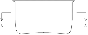
Fig. 1 is the structural representation of the utility model;
Fig. 2 is that A among Fig. 1 is to cutaway view.
Among the figure: 1. inner bag body, 2. base enamel layer, 3. cover-coat enamel layer.
The specific embodiment
Below in conjunction with accompanying drawing and specific embodiment the utility model is further specified.
A kind of cooker pot body inner-tube structure as shown in fig. 1 has inner bag body 1, on inner bag body 1 inwall, successively with base enamel layer 2, cover-coat enamel layer 3, has base enamel layer 2 on inner bag body 1 outer wall.Said inner bag body 1 is SPCC iron plate system inner bag body, also adopts other metal material that is fit to preparations such as iron.Said base enamel layer thickness is 100-120 μ m.Said cover-coat enamel layer thickness is 100-120 μ m.
The whole machining process process of pot body inner bag is as follows:
1, with SPCC iron plate punch forming pot body inner bag body; 2, pot body inner bag body surface carries out the scrubbing oven dry; 3, pot body inner bag body surfaces externally and internally carries out the ground-coat enamel application of slip, dries and forms by a firing; 4, pot body inner bag body surfaces externally and internally carries out the cover-coat enamel application of slip, dries and forms by a firing; 5, a pot body inner bag surface is carried out the applique oven dry and is formed by a firing.
The inner-tube structure of the invention changes original teflon coatings into enamel layer, and enamel itself is nontoxic, and hardness is high, and has good heat insulation effect, resistance to acids and bases, under heat, also can not discharge noxious material.Because the enamel layer difficult drop-off, the better protection metal inner tube is not corroded, and than high two to the three times durability of aluminium courage, increases substantially service life.Enamel layer can be made shades of colour or at the enamel layer surface rendering various patterns arranged simultaneously, has strengthened the aesthetic property of inner bag, makes inner bag characteristic.
Claims (4)
1. a cooker pot body inner-tube structure has the inner bag body, it is characterized in that: on the inner bag inner body wall, successively with base enamel layer, cover-coat enamel layer, have the base enamel layer on the inner bag body outer wall.
2. a kind of cooker pot body inner-tube structure described in claim 1, it is characterized in that: said inner bag body is a SPCC iron plate inner bag body.
3. a kind of cooker pot body inner-tube structure described in claim 1, it is characterized in that: said base enamel layer thickness is 100-120 μ m.
4. a kind of cooker pot body inner-tube structure described in claim 1, it is characterized in that: said cover-coat enamel layer thickness is 100-120 μ m.
Priority Applications (1)
| Application Number | Priority Date | Filing Date | Title |
|---|---|---|---|
| CN201120336034XU CN202223051U (en) | 2011-09-08 | 2011-09-08 | Inner liner structure of cooker pan |
Applications Claiming Priority (1)
| Application Number | Priority Date | Filing Date | Title |
|---|---|---|---|
| CN201120336034XU CN202223051U (en) | 2011-09-08 | 2011-09-08 | Inner liner structure of cooker pan |
Publications (1)
| Publication Number | Publication Date |
|---|---|
| CN202223051U true CN202223051U (en) | 2012-05-23 |
Family
ID=46073662
Family Applications (1)
| Application Number | Title | Priority Date | Filing Date |
|---|---|---|---|
| CN201120336034XU Expired - Fee Related CN202223051U (en) | 2011-09-08 | 2011-09-08 | Inner liner structure of cooker pan |
Country Status (1)
| Country | Link |
|---|---|
| CN (1) | CN202223051U (en) |
Cited By (1)
| Publication number | Priority date | Publication date | Assignee | Title |
|---|---|---|---|---|
| CN113598579A (en) * | 2021-08-09 | 2021-11-05 | 赵晓彪 | Method for manufacturing enamel vacuum cup |
-
2011
- 2011-09-08 CN CN201120336034XU patent/CN202223051U/en not_active Expired - Fee Related
Cited By (1)
| Publication number | Priority date | Publication date | Assignee | Title |
|---|---|---|---|---|
| CN113598579A (en) * | 2021-08-09 | 2021-11-05 | 赵晓彪 | Method for manufacturing enamel vacuum cup |
Similar Documents
| Publication | Publication Date | Title |
|---|---|---|
| CN101999839A (en) | Energy-saving thermal insulating pot | |
| CN201223273Y (en) | Electromagnetic heating non-iron metal cooker | |
| CN201070282Y (en) | Combined healthy non-cooking fume frying-pan of iron and aluminum | |
| CN202223051U (en) | Inner liner structure of cooker pan | |
| CN203447072U (en) | Three-layer compound non-stick pan | |
| CN201108321Y (en) | Multiple layer double layers bottom iron pan | |
| CN201260613Y (en) | Novel cooker body structure | |
| CN201814366U (en) | Aluminum cooking utensil | |
| CN204120837U (en) | Pot, electric cooker and rely on the grill pan tool of work about electric power | |
| CN210727506U (en) | Iron pan | |
| CN203970057U (en) | Compound pot | |
| CN203555609U (en) | Stainless steel ceramic composite bottom pan | |
| CN201197631Y (en) | Electromagnetism dishware | |
| CN201227151Y (en) | Electromagnetic heating iron pan without oil smoke | |
| CN208941674U (en) | Ceramic cooker structure | |
| CN209018380U (en) | Cooking apparatus and electromagnetism furnace module | |
| CN208301468U (en) | Cookware and cooking apparatus | |
| CN202408533U (en) | ceramic-imitated pot | |
| CN207912565U (en) | A kind of IH electric cooker ceramic liners with metal shell | |
| CN202184604U (en) | Non-lampblack frying pan using composite material | |
| CN202112854U (en) | Porcelain pot | |
| CN2305125Y (en) | Non-sticked pan for electromagnetic oven | |
| CN201234897Y (en) | Multi-bottom boiler liner | |
| CN2910034Y (en) | Pot ware able to be electromagneticall heated | |
| CN202775813U (en) | Nanometer ceramic non-stick pan |
Legal Events
| Date | Code | Title | Description |
|---|---|---|---|
| C14 | Grant of patent or utility model | ||
| GR01 | Patent grant | ||
| TR01 | Transfer of patent right | ||
| TR01 | Transfer of patent right |
Effective date of registration: 20170717 Address after: 519000 Guangdong city of Zhuhai province Hengqin Baohua Road No. 6, room 105, -30288 (central office) Patentee after: Zhuhai taimi Technology Co. Ltd. Address before: 701, room 2, unit 1001, Fenghuang Fenghuang Road, Xiangzhou District, Guangdong, Zhuhai, Xiangzhou 519000, China Patentee before: Li Baisheng |
|
| CF01 | Termination of patent right due to non-payment of annual fee | ||
| CF01 | Termination of patent right due to non-payment of annual fee |
Granted publication date: 20120523 Termination date: 20190908 |