CN202180228U - Numerical-control vertical fine boring mill - Google Patents
Numerical-control vertical fine boring mill Download PDFInfo
- Publication number
- CN202180228U CN202180228U CN2011202238270U CN201120223827U CN202180228U CN 202180228 U CN202180228 U CN 202180228U CN 2011202238270 U CN2011202238270 U CN 2011202238270U CN 201120223827 U CN201120223827 U CN 201120223827U CN 202180228 U CN202180228 U CN 202180228U
- Authority
- CN
- China
- Prior art keywords
- belt wheel
- ball screw
- workbench
- column
- main shaft
- Prior art date
- Legal status (The legal status is an assumption and is not a legal conclusion. Google has not performed a legal analysis and makes no representation as to the accuracy of the status listed.)
- Expired - Lifetime
Links
Images

Abstract
The utility model provides a numerical-control vertical fine boring mill, which comprises an upright column (1), a base (2), a pedestal (4), a workbench (5), a spindle (6), a single spindle head (7) and a carriage (10). The numerical-control vertical fine boring mill is characterized in that the pedestal (4) is connected with the workbench (5) by a ball screw (21), a belt pulley (20) is mounted on the ball screw (21), a belt pulley (24) is mounted on a servo motor (23), the belt pulley (20) is connected with the belt pulley (24) by a synchronous toothed belt (22), the carriage (10) is connected with the upright column (1) by a ball screw (14), a belt pulley (13) is mounted on the ball screw (14), a belt pulley (17) is mounted on a carriage servo motor (16), the belt pulley (13) is connected with the belt pulley (17) by a synchronous toothed belt (15), the single spindle head (7) and the spindle (6) are mounted on the carriage (10), the spindle drives a motor (12) to rotate, a belt pulley (8) is mounted on the single spindle head (7), a belt pulley (11) is mounted on a spindle transmission motor (12), the belt pulley (8) is connected with the belt pulley (11) by a synchronous toothed belt (9), and a numerical-control system control box (19) is mounted on the upright column (1). The numerical-control vertical fine boring mill is convenient in control and high in positioning precision and processing efficiency.
Description
Technical field
The utility model relates to a kind of digital control vertical fine boring machine.
Background technology
Fast development along with manufacturings such as military project, automobile, mould, boats and ships; Especially the streamline production technology applies rapidly; Vertical fine boring machine improves machining accuracy enlarging the range of work, improves automatization level; Aspect such as raise labour productivity and proposed increasingly high requirement makes the application of vertical fine boring machine develop to manufacturing from maintenance industry.But existing common vertical fine boring machine is common electrical control basically; Use common screw mandrel to drive workbench, use moving and rotation of mechanical gear control main shaft, cause the positioning accuracy of common vertical fine boring machine not high; The translational speed of lathe moving-member, the rotating speed of main shaft are difficult to adjustment; Make the application and the control more complicated of common vertical fine boring machine, working (machining) efficiency is lower, and product applications is restricted.
Summary of the invention
The purpose of the utility model is to remedy above-mentioned deficiency, the digital control vertical fine boring machine that provide a kind of and control conveniently, positioning accuracy is high, working (machining) efficiency is high.
The utility model is achieved in that and comprises column 1, pedestal 2, pedestal 4; Workbench 5, main shaft 6, single shaft head 7; Balladeur train 10 is characterized in that connecting installment work platform ball screw belt wheel 20 on the workbench ball screw 21 with workbench ball screw 21 between pedestal 4 and the workbench 5; Servomotor belt wheel 24 is installed on the workbench servomotor 23, is connected with workbench synchronous cog belt 22 between workbench ball screw belt wheel 20 and the workbench servomotor belt wheel 24; Use column ball screw 14 to connect between balladeur train 10 and the column 1; Column ball screw belt wheel 13 is installed on the column ball screw 14; Balladeur train servomotor belt wheel 17 is installed on the balladeur train servomotor 16, is connected with column synchronous cog belt 15 between balladeur train servomotor belt wheel 17 and the column ball screw belt wheel 13; Single shaft head 7 and main shaft 6, main shaft rotary electric machine 12 are installed on the balladeur train 10, main shaft belt wheel 8 is installed on the single shaft head 7, spindle electrical machine belt pulley 11 is installed on the spindle motor 12, connect with main shaft synchronous cog belt 9 between main shaft belt wheel 8 and the spindle motor belt wheel 11; Digital control system control cabinet 19 is installed on the column 1.
Each moving-member of the utility model adopts the ball screw transmission; Reduce the friction between screw mandrel and nut; Improve the translational speed of moving component; Use digital control system control servomotor and main shaft variable-frequency motor and use timing belt and belt wheel; Make all to be simplified in the control of manufacturing and vertical boring mill of rotating speed, machine tool element of translational speed, main shaft of vertical boring mill moving-member that the positioning accuracy of vertical boring mill also is improved, the vertical boring mill working (machining) efficiency has obtained significant raising.The utility model is not only applicable to repairing trades, also can extensive use in manufacturing.
Description of drawings:
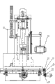
Fig. 1 is the left view of the utility model structural representation.
Fig. 2 is the front view of the utility model structural representation.
Among the figure: 1-column, 2-pedestal, 3-handwheel, 4-pedestal, 5-workbench; The 6-main shaft, 7-single shaft head, 8-main shaft belt wheel, 9-main shaft timing belt, 10-balladeur train; 11-spindle motor belt wheel, 12-spindle motor, 13-column ball screw belt wheel, 14-column ball screw, 15-column timing belt; 16-balladeur train servomotor, 17-balladeur train servomotor belt wheel, 18-electric box, 19-digital control system control cabinet, 20-workbench ball screw belt wheel; 21-workbench ball screw, 22-workbench timing belt, 23-workbench servomotor, 24-servomotor belt wheel.
The specific embodiment:
Further describe below in conjunction with the specific embodiment of accompanying drawing the utility model.
As shown in the figure; Pedestal 2 front portions are equipped with pedestal 4; Pedestal 2 is connected with pedestal 4 usefulness screw mandrels, and workbench 5 is installed on the pedestal 4, and 5 of pedestal 4 and workbench are connected with workbench ball screw 21; Can make pedestal 4 and workbench 5 do laterally moving of front and back through handwheel 3; Servomotor and ball screw also can be installed use digital control system and servomotor control to move laterally (Y to), installment work platform servomotor belt wheel 24 and workbench ball screw belt wheel 20 respectively on workbench servomotor 23 and the workbench ball screw 21, by workbench servomotor 23 through synchronizing jugged 22 drive workbench 5 deceleration transmission and mobile (X to); Thereby improve the carry-over moment of workbench servomotor 23, thereby the power that under identical moment requires, can reduce servomotor reaches energy-conservation effect.
Column 1 is installed in pedestal 2 rear portions; Column 1 is equipped with balladeur train 10 through guide rail and column ball screw 14; The moving of balladeur train 10 (Z to) drives column ball screws 14 through column synchronous cog belt 15 by balladeur train servomotor 16 with column ball screw belt wheel 13, balladeur train servomotor belt wheel 17 and rotates and realize; Big or small proportioning through synchronizing jugged belt wheel can be carried out deceleration transmission; Improve the carry-over moment of balladeur train servomotor 16, thereby the power that under identical moment requires, can reduce servomotor reaches energy-conservation effect.
Single shaft head 7, main shaft 6 and spindle motor 12 are installed on the balladeur train 10, main shaft belt wheel 8 is installed on the single shaft head 7, spindle motor belt wheel 11 is installed on the balladeur train 10; Main shaft belt wheel 8 passes through the rotation of main shaft synchronous cog belt 9 by spindle motor 12 driving main shaft 6 with spindle motor 12; Main shaft belt wheel 8 is bigger, and spindle motor belt wheel 11 is less, transmits to realize slowing down; Thereby the power that under identical moment requires, can reduce motor reaches energy-conservation effect; Spindle motor 12 uses variable-frequency motor or main axle servo motors, thereby has reduced mechanical gear, can reach electrodeless variable-speed stably again simultaneously reducing the parts manufacture difficulty.
The digital control system of lathe is installed in the electric box 18 and digital control system control cabinet 19 of column 1 both sides; Digital control system comprises servomotor and the servo-driver of each; And servomotor and servo-driver, spindle dynamo-electric 17 and the variable frequency drives thereof of controlling each realize the motion of each moving-member, rotary part, and digital control system can be used diaxon or three axle systems according to requirements of different users.
The utility model is owing to adopted ball screw; The translational speed and the positioning accuracy of moving component have been improved; And use the rotation that reaches main shaft of moving of digital control system control and driven by servomotor workbench, balladeur train and main shaft; Make the control and the making of lathe oversimplify, the adjustment of the rotation rotating speed of lathe moving-member translational speed and main shaft is also because of having used digital control system no longer complicated.
Claims (2)
1. a digital control vertical fine boring machine comprises column (1), pedestal (2); Pedestal (4), workbench (5), main shaft (6); Single shaft head (7); Balladeur train (10) is characterized in that connecting with workbench ball screw (21) between pedestal (4) and the workbench (5), and workbench ball screw (21) is gone up installment work platform ball screw belt wheel (20); Workbench servomotor (23) is gone up servomotor belt wheel (24) is installed, and connects with workbench synchronous cog belt (22) between workbench ball screw belt wheel (20) and the workbench servomotor belt wheel (24); Use column ball screw (14) to connect between balladeur train (10) and the column (1); Column ball screw (14) is gone up column ball screw belt wheel (13) is installed; Balladeur train servomotor (16) is gone up balladeur train servomotor belt wheel (17) is installed, and connects with column synchronous cog belt (15) between balladeur train servomotor belt wheel (17) and the column ball screw belt wheel (13); Balladeur train (10) is upward installed single shaft head (7) and main shaft (6), main shaft rotary electric machine (12); Single shaft head (7) is gone up main shaft belt wheel (8) is installed; Spindle motor (12) is gone up spindle electrical machine belt pulley (11) is installed, and connects with main shaft synchronous cog belt (9) between main shaft belt wheel (8) and the spindle motor belt wheel (11); Column (1) is gone up digital control system control cabinet (19) is installed.
2. digital control vertical fine boring machine according to claim 1 is characterized in that main shaft belt wheel (8) is bigger, and spindle motor belt wheel (11) is less.
Priority Applications (1)
| Application Number | Priority Date | Filing Date | Title |
|---|---|---|---|
| CN2011202238270U CN202180228U (en) | 2011-06-29 | 2011-06-29 | Numerical-control vertical fine boring mill |
Applications Claiming Priority (1)
| Application Number | Priority Date | Filing Date | Title |
|---|---|---|---|
| CN2011202238270U CN202180228U (en) | 2011-06-29 | 2011-06-29 | Numerical-control vertical fine boring mill |
Publications (1)
| Publication Number | Publication Date |
|---|---|
| CN202180228U true CN202180228U (en) | 2012-04-04 |
Family
ID=46173277
Family Applications (1)
| Application Number | Title | Priority Date | Filing Date |
|---|---|---|---|
| CN2011202238270U Expired - Lifetime CN202180228U (en) | 2011-06-29 | 2011-06-29 | Numerical-control vertical fine boring mill |
Country Status (1)
| Country | Link |
|---|---|
| CN (1) | CN202180228U (en) |
Cited By (5)
| Publication number | Priority date | Publication date | Assignee | Title |
|---|---|---|---|---|
| CN102825300A (en) * | 2012-08-31 | 2012-12-19 | 常熟市中恒数控设备制造有限公司 | Taper hole boring device of NC (Numerical Control) boring lathe |
| CN102825295A (en) * | 2012-08-31 | 2012-12-19 | 常熟市中恒数控设备制造有限公司 | Taper hole boring device of numerical control boring mill |
| CN102825297A (en) * | 2012-08-31 | 2012-12-19 | 常熟市中恒数控设备制造有限公司 | Taper hole boring device for numerical control boring mill |
| CN104942335A (en) * | 2015-06-09 | 2015-09-30 | 安庆联控机电科技发展有限公司 | Piston ring boring machine with specification fixed adjustment device |
| CN105364117A (en) * | 2015-11-20 | 2016-03-02 | 盐城苏工高科机械有限公司 | Vertical boring machine for elevator brake pads |
-
2011
- 2011-06-29 CN CN2011202238270U patent/CN202180228U/en not_active Expired - Lifetime
Cited By (7)
| Publication number | Priority date | Publication date | Assignee | Title |
|---|---|---|---|---|
| CN102825300A (en) * | 2012-08-31 | 2012-12-19 | 常熟市中恒数控设备制造有限公司 | Taper hole boring device of NC (Numerical Control) boring lathe |
| CN102825295A (en) * | 2012-08-31 | 2012-12-19 | 常熟市中恒数控设备制造有限公司 | Taper hole boring device of numerical control boring mill |
| CN102825297A (en) * | 2012-08-31 | 2012-12-19 | 常熟市中恒数控设备制造有限公司 | Taper hole boring device for numerical control boring mill |
| CN102825300B (en) * | 2012-08-31 | 2014-04-16 | 常熟市中恒数控设备制造有限公司 | Taper hole boring device of NC (Numerical Control) boring lathe |
| CN102825297B (en) * | 2012-08-31 | 2014-07-23 | 常熟市中恒自动化设备有限公司 | Taper hole boring device for numerical control boring mill |
| CN104942335A (en) * | 2015-06-09 | 2015-09-30 | 安庆联控机电科技发展有限公司 | Piston ring boring machine with specification fixed adjustment device |
| CN105364117A (en) * | 2015-11-20 | 2016-03-02 | 盐城苏工高科机械有限公司 | Vertical boring machine for elevator brake pads |
Similar Documents
| Publication | Publication Date | Title |
|---|---|---|
| CN202180228U (en) | Numerical-control vertical fine boring mill | |
| CN201192779Y (en) | Five-axis numerical control milling machine | |
| CN103264229A (en) | Multi-station laser cutting machine tool | |
| CN201799672U (en) | Tire die tread pattern fine-milling machine | |
| CN201862863U (en) | Machine tool layout of vertical four-axle numerical control gear shaving machine | |
| CN102615573A (en) | Bridge type numerical control planogrinder structure | |
| CN204019268U (en) | Five-shaft high-speed interlock machining center | |
| CN204397367U (en) | A kind of dynamic post and beam gantry Five-axis NC Machining Center | |
| CN2923166Y (en) | Multi-shaft machine tool | |
| CN106624189A (en) | Numerical control grinder for forming machining | |
| CN110814754A (en) | Numerical control machine tool capable of realizing turning and milling composite processing of non-rotating curved surface | |
| CN202606950U (en) | Double-headed vertical milling machine | |
| CN204094203U (en) | A kind of vertical double-sided milling machine | |
| CN204545528U (en) | CNC milling machine | |
| CN202123874U (en) | Numeric-control engraving machine for large-size wood patterns | |
| CN104117739B (en) | Horizontal type taper-shaped chamfering machine for processing numerical control gear | |
| CN201702463U (en) | Straight bevel gear machine tool | |
| CN202845955U (en) | Machine tool of six-spindle spiral bevel gear milling machine | |
| CN203045399U (en) | Gantry machining center capable of moving beam | |
| CN104802040A (en) | Double-head multipurpose machine tool | |
| CN202185650U (en) | Six-axis numerical-control rotary separating chamfering machine for gears | |
| CN210968236U (en) | Desktop multi-axis milling and grinding microcomputer machine | |
| CN203092127U (en) | Lathing and grinding combined machining machine tool | |
| CN102825314B (en) | Field slot milling machine of taper inner hole | |
| CN201172118Y (en) | Multifunctional common universal milling machine |
Legal Events
| Date | Code | Title | Description |
|---|---|---|---|
| C14 | Grant of patent or utility model | ||
| GR01 | Patent grant | ||
| TR01 | Transfer of patent right |
Effective date of registration: 20200201 Address after: 653100 No. 14, Guanyin Mountain Industrial Zone, Hongta Industrial Park, Hongta District, Yuxi, Yunnan. Patentee after: YUXI JIANFU GROUP MACHINE TOOL CO., LTD. Address before: Lijiang City, Yunnan province 674100 City District South Road Patentee before: Yunnan Lijiang Machine Tool Co., Ltd. |
|
| TR01 | Transfer of patent right | ||
| CX01 | Expiry of patent term |
Granted publication date: 20120404 |
|
| CX01 | Expiry of patent term |