CN202169053U - Leg exerciser - Google Patents
Leg exerciser Download PDFInfo
- Publication number
- CN202169053U CN202169053U CN2011202662728U CN201120266272U CN202169053U CN 202169053 U CN202169053 U CN 202169053U CN 2011202662728 U CN2011202662728 U CN 2011202662728U CN 201120266272 U CN201120266272 U CN 201120266272U CN 202169053 U CN202169053 U CN 202169053U
- Authority
- CN
- China
- Prior art keywords
- foot rest
- frame
- fork
- cushion
- sleeve pipe
- Prior art date
- Legal status (The legal status is an assumption and is not a legal conclusion. Google has not performed a legal analysis and makes no representation as to the accuracy of the status listed.)
- Expired - Fee Related
Links
Images


Landscapes
- Rehabilitation Tools (AREA)
Abstract
The utility model discloses a leg exerciser, comprising a frame, a cushion, a back rest, a hand rest, a swing rod, an elastic slice, a foot rest, a pedal, wherein the cushion, the hand rest and the back rest are mounted on the frame. One end of the swing rod is hinged with the bottom of the top part of the frame, another end of the swing rod fixedly passes through the inner end of the foot rest; the foot rest is a bending pipe, two ends of the elastic slice are respectively hung on an inner connection axle of the elastic slice of the foot rest and an outer connection axle of the elastic slice on the front end of the frame; the pedal is mounted on the outer end of the foot rest in a swinging way. The leg exerciser is mainly composed of the frame and the cushion, thus the structure of the leg exerciser is very simple and during the exercising process, the leg is exercised and the abdominal part is also very well exercised.
Description
Technical field
The utility model relates to a kind of body-building apparatus, particularly relates to a kind of leg exerciser.
Background technology
Along with the progress in epoch, the abundance that is well off, in well-fed and well-clothed, obesity is following; And the sequelae of bringing along with obesity also emerges in an endless stream, and such as hypertension, heart disease etc., and most of young man can't accept to integrate proud flesh oneself especially; And be directed against the working clan, before being sitting in desk and computer all day, make food build-up under one's belt; Can't digest smoothly, cause the situation of protruding tummy, also make the working clan feel puzzlement very much.Therefore; Just occur many on the market to buttocks, thigh fat-reducing and body shaping equipment; Many equipment to abdominal exercise particularly occurred, but the non-general working clan of the consumption of this kind equipment can afford, in view of this; Many various sports equipments promptly are developed like the mushrooms after rain, to adapt to the demand of society.
The utility model content
The purpose of the utility model is to provide a kind of simple in structure, leg exerciser that train on is good.
For realizing above-mentioned purpose, the technical solution of the utility model is:
The utility model is a kind of leg exerciser, and it comprises frame, cushion, backrest, handrail, fork, bouncing plate, foot rest, pedal; Described cushion is installed in the end face of frame top, and handrail is installed in the side of frame top, and backrest is installed in the rear portion and oblique the making progress of frame; One end of described fork is hinged on the bottom surface at the top of frame, and is positioned at the below of cushion, and the other end of fork fixedly is set in the inner of foot rest; Described foot rest is a bending tube, and it locates the oblique connecting axle in two symmetrically arranged bouncing plates that outwards is provided with near the inner; Described bouncing plate has two, and the two ends of bouncing plate are articulated in the interior connecting axle of bouncing plate of foot rest respectively and are located on the outer connecting axle of bouncing plate of frame front end; The outer end that is installed in foot rest that described pedal can be swung.
Described frame is saddle, and it is made up of preceding foot rest, crossbeam and rear leg, and the middle part of preceding foot rest and rear leg is fixed in the two ends of crossbeam respectively; Described handrail is made up of two bend pipes, is symmetricly set on respectively on the crossbeam of frame top.
Described foot rest is made up of bend pipe and sleeve pipe; Described sleeve pipe activity is plugged on the outer end of bend pipe, and bend pipe inner fixedly sleeved on fork is provided with the plum blossom bolt that is used for fixing both in the socket section of bend pipe and sleeve pipe.
Described fork comprises connecting rod, nut, bolt, plunger; Described connecting rod top is a sleeve pipe, and the bottom is a screw rod, and two nuts of relatively establishing are nested with in sleeve pipe and through the bottom surface of bolted splice at the top of frame, and screw rod fixedly is set in the inner of foot rest through being nested with plunger on it.
After adopting such scheme; Because the utility model mainly is made up of parts such as frame, cushion, backrest, handrail, fork, bouncing plate, foot rest, pedals; Structure is very simple; And the utility model not only makes shank obtain taking exercise, and belly is also had good train on when exercise.
Below in conjunction with accompanying drawing and specific embodiment the utility model is further described.
Description of drawings
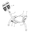
Fig. 1 is the axonometric drawing of the utility model;
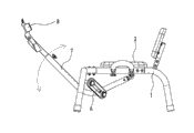
Fig. 2 is the three-dimensional exploded view of the utility model;
Fig. 3 is the utility model swing state diagram;
Fig. 4 is the utility model state diagram that swings.
The specific embodiment
Like Fig. 1, shown in Figure 2, the utility model is a kind of leg exerciser, and it comprises frame 1, cushion 2, backrest 3, handrail 4, fork 5, bouncing plate 6, foot rest 7, pedal 8.
Described frame 1 is saddle, and it is made up of preceding foot rest 11, crossbeam 12 and rear leg 13.The middle part of preceding foot rest 11 and rear leg 13 is fixed in the two ends of crossbeam 12 respectively; On preceding foot rest 11, be symmetrical set connecting axle 111 outside the bouncing plate respectively.
Described cushion 2 is installed in the end face at frame 1 crossbeam 12 tops, and handrail 4 is installed in the side at frame 1 crossbeam 12 tops, and backrest 3 is installed in the rear portion and oblique the making progress of frame 1 crossbeam 12.
Described foot rest 7 is a bending tube, is made up of bend pipe 71 and sleeve pipe 72; Described sleeve pipe 72 activities are plugged on the outer end of bend pipe 71, are provided with the plum blossom bolt 73 that is used for fixing both in the socket section of bend pipe 71 and sleeve pipe 72.Locating the oblique connecting axle 74 in two symmetrically arranged bouncing plates that outwards is provided with near bend pipe 71 the inners.
Described fork 5 comprises connecting rod 51, nut 52, bolt 53, plunger 54.Described connecting rod 51 tops are a sleeve pipe 511; The bottom is a screw rod 512; Two nuts of relatively establishing 52 be nested with the bottom surface of top 1 crossbeam 12 that is hinged on frame 1 in sleeve pipe 511 and through bolt 53 and be positioned at cushion 2 below, screw rod 512 fixedly is set in the inners of foot rest 7 bend pipes 71 through being nested with plunger 54 on it.
Described bouncing plate 6 has two, and the two ends of bouncing plate 6 are articulated in respectively in the bouncing plate of foot rest 7 on the connecting axle 74 and the outer connecting axle 111 of the bouncing plate of being located at frame 1 front end and respectively by plum blossom bolt 75 and 14 lockings of plum blossom bolt.The outer end that is installed in foot rest 7 that described pedal 8 can be swung.
Described handrail 4 is made up of two bend pipes, is symmetricly set on respectively on the crossbeam 12 at frame 1 top, holds to make things convenient for the user.
Like Fig. 3, shown in Figure 4, the user is sitting on the cushion 2, and pin is being stepped on pedal 8, overcomes the pulling force of bouncing plate 6, and driving foot rest 7 carries out swing around the foot rest 7 and the hinged place of frame 1 or swings, thereby reaches the exercise purpose.
The above; Be merely the utility model preferred embodiment; So can not limit the scope that the utility model is implemented with this, the equivalence of promptly doing according to the utility model claim and description changes and modifies, and all should still belong in the scope that the utility model patent contains.
Claims (4)
1. leg exerciser, it is characterized in that: it comprises frame, cushion, backrest, handrail, fork, bouncing plate, foot rest, pedal; Described cushion is installed in the end face of frame top, and handrail is installed in the side of frame top, and backrest is installed in the rear portion and oblique the making progress of frame; One end of described fork is hinged on the bottom surface at the top of frame, and is positioned at the below of cushion, and the other end of fork fixedly is set in the inner of foot rest; Described foot rest is a bending tube, and it locates the oblique connecting axle in two symmetrically arranged bouncing plates that outwards is provided with near the inner; Described bouncing plate has two, and the two ends of bouncing plate are articulated in the interior connecting axle of bouncing plate of foot rest respectively and are located on the outer connecting axle of bouncing plate of frame front end; The outer end that is installed in foot rest that described pedal can be swung.
2. leg exerciser according to claim 1 is characterized in that: described frame is saddle, and it is made up of preceding foot rest, crossbeam and rear leg, and the middle part of preceding foot rest and rear leg is fixed in the two ends of crossbeam respectively; Described handrail is made up of two bend pipes, is symmetricly set on respectively on the crossbeam of frame top.
3. leg exerciser according to claim 1 is characterized in that: described foot rest is made up of bend pipe and sleeve pipe; Described sleeve pipe activity is plugged on the outer end of bend pipe, and bend pipe inner fixedly sleeved on fork is provided with the plum blossom bolt that is used for fixing both in the socket section of bend pipe and sleeve pipe.
4. leg exerciser according to claim 1 is characterized in that: described fork comprises connecting rod, nut, bolt, plunger; Described connecting rod top is a sleeve pipe, and the bottom is a screw rod, and two nuts of relatively establishing are nested with in sleeve pipe and through the bottom surface of bolted splice at the top of frame, and screw rod fixedly is set in the inner of foot rest through being nested with plunger on it.
Priority Applications (1)
| Application Number | Priority Date | Filing Date | Title |
|---|---|---|---|
| CN2011202662728U CN202169053U (en) | 2011-07-26 | 2011-07-26 | Leg exerciser |
Applications Claiming Priority (1)
| Application Number | Priority Date | Filing Date | Title |
|---|---|---|---|
| CN2011202662728U CN202169053U (en) | 2011-07-26 | 2011-07-26 | Leg exerciser |
Publications (1)
| Publication Number | Publication Date |
|---|---|
| CN202169053U true CN202169053U (en) | 2012-03-21 |
Family
ID=45827258
Family Applications (1)
| Application Number | Title | Priority Date | Filing Date |
|---|---|---|---|
| CN2011202662728U Expired - Fee Related CN202169053U (en) | 2011-07-26 | 2011-07-26 | Leg exerciser |
Country Status (1)
| Country | Link |
|---|---|
| CN (1) | CN202169053U (en) |
Cited By (1)
| Publication number | Priority date | Publication date | Assignee | Title |
|---|---|---|---|---|
| GB2580617A (en) * | 2019-01-15 | 2020-07-29 | Collinge Richard | Seat apparatus for an aircraft or similar |
-
2011
- 2011-07-26 CN CN2011202662728U patent/CN202169053U/en not_active Expired - Fee Related
Cited By (1)
| Publication number | Priority date | Publication date | Assignee | Title |
|---|---|---|---|---|
| GB2580617A (en) * | 2019-01-15 | 2020-07-29 | Collinge Richard | Seat apparatus for an aircraft or similar |
Similar Documents
| Publication | Publication Date | Title |
|---|---|---|
| CN104645561B (en) | Sit-ups roller-coaster fitness modular device | |
| CN202169053U (en) | Leg exerciser | |
| CN203860834U (en) | Office chair with exercising function | |
| CN203921097U (en) | A kind of novel manual supports pull-type bicycle | |
| CN204502293U (en) | There is the board for lying on back of auxiliary rail | |
| CN204073237U (en) | Indoor comprehensive training aids | |
| CN202173732U (en) | Training device for situp | |
| CN201192547Y (en) | Multifunctional bench-press bed | |
| CN202409982U (en) | Bodybuilding comprehensive trainer | |
| CN203123453U (en) | Multifunctional fitness trainer | |
| CN202802657U (en) | Multifunctional body-building device | |
| CN203989693U (en) | A kind of Exercycle | |
| CN203139513U (en) | Abdomen exercising equipment | |
| CN202185120U (en) | Belly training frame | |
| CN202740679U (en) | Side horse with adjustable height | |
| CN203235186U (en) | Multipurpose exercise bicycle | |
| CN204395329U (en) | Arm strength comprehensive body exercising machine | |
| CN202860089U (en) | Multifunctional wooden horse | |
| CN204073282U (en) | Multifunctional domestic physical strength training device | |
| CN201572489U (en) | Skiing-like waist-wresting body conditioner | |
| CN202355778U (en) | Buttock fitness chair | |
| CN204034179U (en) | Two push away to pedal stretch exercising machine | |
| CN204502279U (en) | There is the board for lying on back of massage functions | |
| CN202052275U (en) | Spring ability exercise equipment | |
| CN202169049U (en) | Pull rotation trainer |
Legal Events
| Date | Code | Title | Description |
|---|---|---|---|
| C14 | Grant of patent or utility model | ||
| GR01 | Patent grant | ||
| CF01 | Termination of patent right due to non-payment of annual fee |
Granted publication date: 20120321 Termination date: 20180726 |
|
| CF01 | Termination of patent right due to non-payment of annual fee |