CN202149600U - Three times air intake biomass fuel heat conduction oil boiler - Google Patents
Three times air intake biomass fuel heat conduction oil boiler Download PDFInfo
- Publication number
- CN202149600U CN202149600U CN201120163506U CN201120163506U CN202149600U CN 202149600 U CN202149600 U CN 202149600U CN 201120163506 U CN201120163506 U CN 201120163506U CN 201120163506 U CN201120163506 U CN 201120163506U CN 202149600 U CN202149600 U CN 202149600U
- Authority
- CN
- China
- Prior art keywords
- combustion chamber
- boiler
- time
- disposed
- heater
- Prior art date
- Legal status (The legal status is an assumption and is not a legal conclusion. Google has not performed a legal analysis and makes no representation as to the accuracy of the status listed.)
- Expired - Fee Related
Links
Images
Landscapes
- Solid-Fuel Combustion (AREA)
Abstract
The utility model provides a three times air intake biomass fuel heat conduction oil boiler constituted by a combustion hopper, a fire grate, a furnace mouth and a combustion chamber. A heat conduction oil pipe is disposed in the boiler in an enclosed manner, and is communicated with a heat-collecting cylinder. A smoke exhaust channel is disposed on an upper part of one side of the boiler body, and an ash slag pond is disposed on a lower part of one side of the boiler body. A primary air supply port is disposed in a lower part of the boiler body, and a secondary air supply port is disposed in a rear part of the boiler body, besides, a third air supply port is disposed in a wall of an upper part of a furnace arch, and is communicated with lower parts of inferior combustion chambers. By using the boiler provided in the utility model, smoke can be completely combusted after the blowing out of the boiler, thereby the black smoke can be prevented, the utilization rate of the fuel can be improved, and the damage on the environment can be reduced. The three times air intake biomass fuel heat conduction oil boiler provided in the utility model can be used in the production and use of the boiler.
Description
Technical field
What the utility model proposed is the hot conversion equipment in thermal technology field, specifically three air intake biomass fuel heat conducting oil boilers.
Background technology
Existing heat conducting oil boiler air supply mode has end air intake and side air intake, and the boiler of end air intake and side air intake can firing biomass fuel, but biomass fuel gasifies easily; So when blowing out, unburnt gaseous fuel can not get oxygen; So produce unburnt flue gas, enter atmosphere, pollute; And waste fuel, cause the fuel utilization of can not fully burning.
Summary of the invention
In order to realize not producing after the blowing out purpose of black smoke, the utility model provides air intake biomass fuel heat conducting oil boiler three times.This boiler is through installing the air feed mouth additional three times in bottom, inferior combustion chamber, solve fuel gasification combustion fully with the technical problem that improves fuel availability.
The scheme that the utility model technical solution problem is adopted is:
At the anterior fuel hopper of installing of body of heater, in the body of heater bottom fire grate is installed, be provided with fire door in body of heater one side; Be provided with the air feed mouth one time in the fire grate bottom, on the body of heater of back of furnace row, be provided with secondary air feed mouth, chimney arch is housed on fire grate top; The furnace body wall on chimney arch top is provided with the air feed mouth three times, and chimney arch top is main chamber, is provided with the combustion chamber two times at the main chamber rear portion; Top between main chamber and time combustion chamber is provided with burner, and combustion chamber and the burner between the second time combustion chamber are located at the bottom of interlayer for the first time, and the top of combustion chamber is provided with smokejack in the second time; Main chamber is equipped with heat collecting cylinder with the top of time combustion chamber, and heat collecting cylinder top is equipped with safety valve, crowds around on the inboard wall of furnace body that main chamber and time combustion chamber are constituted heat-conducting oil pipes is housed; Constitute heat exchange walls, be provided with grey slag bath at the rear lower of body of heater fire grate.
Good effect, the utility model boiler can be realized flue gas completing combustion after the blowing out, do not produce the effect of black smoke, and have improved the utilization rate of fuel, reduce the pollution of environment.Use in suitable heating boiler production and the use.
Description of drawings
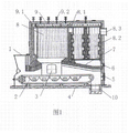
Fig. 1 is the utility model structure chart
Among the figure, 1, fuel hopper, 2. fire grate, 3. fire door, 4. an air feed mouth, 5. secondary air feed mouth; 6. three air feed mouths, 7. chimney arch, 8. main chamber, 8.1. burner, 8.2. combustion chamber; 8.3. smokejack, 9. heat collecting cylinder, 9.1. heat-conducting oil pipes, 9.2. safety valve, 10. grey slag bath.
The specific embodiment
Shown in figure,, fire grate 2 is installed in the body of heater bottom at the anterior fuel hopper 1 of installing of body of heater; Be provided with fire door 3 in body of heater one side, be provided with one time air feed mouth 4 in the fire grate bottom, on the body of heater of back of furnace row, be provided with secondary air feed mouth 5; On fire grate top chimney arch 7 is housed, the furnace body wall on chimney arch top is provided with air feed mouth 6 three times, and chimney arch top is main chamber 8; Be provided with combustion chambers 8.2 two times at the main chamber rear portion, main chamber is provided with burner 8.1 with the top between the combustion chamber for the first time, and the burner between combustion chamber and the second time combustion chamber is located at the bottom of interlayer for the first time; The top of combustion chamber is provided with smokejack 8.3 in the second time, and main chamber is equipped with heat collecting cylinder 9 with the top of time combustion chamber, and heat collecting cylinder top is equipped with safety valve 9.2; Crowd around on the inboard wall of furnace body that main chamber and time combustion chamber are constituted heat-conducting oil pipes 9.1 be housed, constitute heat exchange walls, and with the heat collecting cylinder conducting; Rear lower at the body of heater fire grate is provided with 10, three air feed mouths of grey slag bath and two bottoms, combustion chamber perforations.
The course of work of the utility model
Biomass fuel is encased in the fuel hopper, receives the effect of fire grate transmission to be transferred to the bottom of chimney arch, after lighting; Air enters into the top of fire grate from air feed mouth, directly supplies with the main chamber burning, at this moment; The air that secondary air feed mouth feeds is fired flame and is incorporated into main chamber; The combustible gas that biomass combustion is produced burns away, and the combustion flame that produces through the fuel gas buring process imports in time combustion chamber through burner, contacts with the air of three air feed mouth entering; Most combustible gas of unburned and flue gas are burnt away, discharge through smokejack then.Owing on inboard wall of furnace body, center on and be provided with many heat transfer pipes; Heated conduction oil is focused in the heat collecting cylinder, flow to through pipeline and use hot device, when conduction oil carries out heat exchange and after reducing temperature; Get back to again and continue heating in the boiler, accomplish the heat supplying process of boiler.
When blowing out, in main chamber and time combustion chamber unburned completely flue gas can't contact with the air of air feed and secondary air feed, so cause the sufficient black smoke of unburned to produce, and pass through smokejack and arrange to atmosphere.And the boiler of the utility model is owing to be provided with three times the air feed mouth in the bottom of inferior combustion chamber, so air can contact with the flue gas that do not obtain burning in the inferior combustion chamber, oxidation reaches the purpose and the effect of completing combustion.
Claims (1)
1. three air intake biomass fuel heat conducting oil boilers at the anterior fuel hopper (1) of installing of body of heater, are installed fire grate (2) in the body of heater bottom; Be provided with fire door (3) in body of heater one side, be provided with an air feed mouth (4) in the fire grate bottom, on the body of heater of back of furnace row, be provided with secondary air feed mouth (5); Chimney arch (7) is housed on fire grate top, and chimney arch top is main chamber (8), and the top of combustion chamber is provided with smokejack (8.3) in the second time; Main chamber is equipped with heat collecting cylinder (9) with the top of time combustion chamber, and heat collecting cylinder top is equipped with safety valve (9.2), crowds around on the inboard wall of furnace body that main chamber and time combustion chamber are constituted heat-conducting oil pipes (9.1) is housed; Constitute heat exchange walls; And with the heat collecting cylinder conducting, be provided with grey slag bath (10) at the rear lower of body of heater fire grate, it is characterized in that: the furnace body wall on chimney arch top is provided with three air feed mouths (6); Be provided with two times combustion chamber (8.2) at the main chamber rear portion; Main chamber and for the first time the top between the combustion chamber be provided with burner (8.1), combustion chamber and the burner between the combustion chamber for the second time are located at the bottom of interlayer for the first time, three air feed mouths and two inferior bottoms, combustion chamber perforations.
Priority Applications (1)
| Application Number | Priority Date | Filing Date | Title |
|---|---|---|---|
| CN201120163506U CN202149600U (en) | 2011-05-21 | 2011-05-21 | Three times air intake biomass fuel heat conduction oil boiler |
Applications Claiming Priority (1)
| Application Number | Priority Date | Filing Date | Title |
|---|---|---|---|
| CN201120163506U CN202149600U (en) | 2011-05-21 | 2011-05-21 | Three times air intake biomass fuel heat conduction oil boiler |
Publications (1)
| Publication Number | Publication Date |
|---|---|
| CN202149600U true CN202149600U (en) | 2012-02-22 |
Family
ID=45590658
Family Applications (1)
| Application Number | Title | Priority Date | Filing Date |
|---|---|---|---|
| CN201120163506U Expired - Fee Related CN202149600U (en) | 2011-05-21 | 2011-05-21 | Three times air intake biomass fuel heat conduction oil boiler |
Country Status (1)
| Country | Link |
|---|---|
| CN (1) | CN202149600U (en) |
Cited By (4)
| Publication number | Priority date | Publication date | Assignee | Title |
|---|---|---|---|---|
| CN102705813A (en) * | 2012-06-14 | 2012-10-03 | 熊玉明 | Boiler combustion method for biomass fuel and boiler for biomass fuel |
| CN105737381A (en) * | 2016-04-19 | 2016-07-06 | 湖南长宏锅炉科技股份有限公司 | Biomass burning heat conduction oil furnace |
| CN109737603A (en) * | 2019-03-07 | 2019-05-10 | 广州海诚能源科技有限公司 | A kind of heat conducting oil boiler of biomass burning gas |
| CN112128968A (en) * | 2020-09-14 | 2020-12-25 | 衡阳市大成锅炉有限公司 | High-efficiency low-nitrogen combustion biomass boiler |
-
2011
- 2011-05-21 CN CN201120163506U patent/CN202149600U/en not_active Expired - Fee Related
Cited By (5)
| Publication number | Priority date | Publication date | Assignee | Title |
|---|---|---|---|---|
| CN102705813A (en) * | 2012-06-14 | 2012-10-03 | 熊玉明 | Boiler combustion method for biomass fuel and boiler for biomass fuel |
| CN105737381A (en) * | 2016-04-19 | 2016-07-06 | 湖南长宏锅炉科技股份有限公司 | Biomass burning heat conduction oil furnace |
| CN105737381B (en) * | 2016-04-19 | 2018-08-28 | 湖南长宏锅炉科技股份有限公司 | A kind of biomass-burning heat-conducting oil furnace |
| CN109737603A (en) * | 2019-03-07 | 2019-05-10 | 广州海诚能源科技有限公司 | A kind of heat conducting oil boiler of biomass burning gas |
| CN112128968A (en) * | 2020-09-14 | 2020-12-25 | 衡阳市大成锅炉有限公司 | High-efficiency low-nitrogen combustion biomass boiler |
Similar Documents
| Publication | Publication Date | Title |
|---|---|---|
| CN101338894A (en) | Low-calorie fuel dual prewarming and thermal storage type energy-saving boiler | |
| CN202149600U (en) | Three times air intake biomass fuel heat conduction oil boiler | |
| CN2879022Y (en) | Biomass vaporization boiler | |
| CN102235684A (en) | Three-return-stroke reverse-combustion biomass superconductive hot half gasification furnace | |
| CN104566337A (en) | Novel hearth structure of biomass chain boiler | |
| CN203336576U (en) | High-efficiency energy-saving combined type boiler | |
| CN202002112U (en) | Combustion furnace structure for domestic garbage incineration processing | |
| CN200975687Y (en) | Secondary air heating stove | |
| CN201636841U (en) | Biomass bath-heating non-pressure boiler | |
| CN212339224U (en) | High-temperature oxygen-deficient combustion device for solid fuel | |
| CN201513880U (en) | Integral gasifying combination burning boiler | |
| CN201053699Y (en) | Vertical reverse burning stove | |
| CN201443859U (en) | Double-grate layered mutual combustion-supporting type heating stove for civil use | |
| CN201382443Y (en) | Secondary air inlet combustion-supporting dual-drum heating furnace | |
| CN201215322Y (en) | Cooking stove | |
| CN202012949U (en) | Energy-saving and emission-reducing high temperature furnace | |
| CN203628695U (en) | Gas inlet system of biomass half-gasification boiler | |
| CN201827914U (en) | Energy-saving emission-reducing oven-kang | |
| CN205137544U (en) | Cooking heating stove with water pipe heat exchanger | |
| CN205717897U (en) | Biomass gasification fired environment-protection boiler | |
| CN202012948U (en) | Three-return counter heating type biomass super-thermal-conductive semi-gasification furnace | |
| CN201289109Y (en) | Cooking stove | |
| CN202648119U (en) | Continuous-combustion dual-body heating stove | |
| CN202221107U (en) | Secondary combustion furnace with oxygen supply by hot blast | |
| CN201289068Y (en) | Coal burning coal gasification burning heating stoves |
Legal Events
| Date | Code | Title | Description |
|---|---|---|---|
| C14 | Grant of patent or utility model | ||
| GR01 | Patent grant | ||
| C17 | Cessation of patent right | ||
| CF01 | Termination of patent right due to non-payment of annual fee |
Granted publication date: 20120222 Termination date: 20130521 |