CN202087680U - Novel cantilever type punching die - Google Patents
Novel cantilever type punching die Download PDFInfo
- Publication number
- CN202087680U CN202087680U CN2011200269698U CN201120026969U CN202087680U CN 202087680 U CN202087680 U CN 202087680U CN 2011200269698 U CN2011200269698 U CN 2011200269698U CN 201120026969 U CN201120026969 U CN 201120026969U CN 202087680 U CN202087680 U CN 202087680U
- Authority
- CN
- China
- Prior art keywords
- die
- punch
- guide
- cantilever type
- male
- Prior art date
- Legal status (The legal status is an assumption and is not a legal conclusion. Google has not performed a legal analysis and makes no representation as to the accuracy of the status listed.)
- Expired - Fee Related
Links
Images
Abstract
The utility model discloses a novel cantilever type punching die and relates to a stamping tool. The novel cantilever type punching die comprises an upper die base, a lower die base, a die shank, a male die, a female die, a guide bush and a guide column. The male die is fixedly connected with the lower portion of the upper die base through a male die fixing plate, a filling plate is arranged between the male die and the upper die base, a discharging plate is arranged on the male die, the discharging plate is provided with a discharging spring, the female die is fixedly connected with the position corresponding to the male die on the upper surface of the lower die base through an L-shaped female die seat, a blank holder is in sleeved connection with the outside of the male die, the lower end face of the blank holder is at the same level with the lower surface of the discharging plate, and a ball is arranged in the clearance where the guide bush and the guide column are fitted. The novel cantilever type punching die is large in material stamping force, capable of effectively avoiding bends and crinkles, high in accuracy due to high guide accuracy of the guide bush and the guide column, good in quality and quite practical.
Description
Technical field
The utility model relates to a kind of diel, relates in particular to a kind of novel cantilevered perforating die.
Background technology
In punching production, usually need punching on jatharapanvartanasana workpiece (as cylindrical member, box part, large-scale covering etc.) sidewall, generally be to use the cantilevered perforating die, the die of existing cantilevered perforating die is horizontally disposed with, need be placed in towards the workpiece of side opening on the die, vertical punch moves downward under the drive of forcing press, finishes the moulding of side opening.The stripper of existing cantilevered perforating die is finished the work of binder and discharging simultaneously, and its pressure-plate-force is little, usually causes the workpiece vault to bend up wrinkle, and the guide pin bushing of existing in addition cantilevered perforating die and the guiding accuracy of guide pillar are not high, causes the dimensional accuracy of workpiece low.
Summary of the invention
At the problem that above-mentioned prior art exists, the utility model provides a kind of novel cantilevered perforating die, and pressure-plate-force is big, can effectively avoid the workpiece vault to bend up wrinkle, the guiding accuracy height of the utility model guide pin bushing and guide pillar makes product precision height in addition, quality is good, and is very practical.
The technical solution of the utility model is: a kind of novel cantilevered perforating die, comprise upper bolster, die shoe, die shank, punch, die, guide pin bushing and guide pillar, punch is fixedly connected on the upper bolster below by punch retainer, be provided with backing plate between punch and the upper bolster, punch is provided with stripper, stripper is provided with the discharging spring, die is fixedly connected on the die shoe upper surface position corresponding with punch by L shaped die socket, punch is socketed with blank holder outward, the lower surface of blank holder flushes with the lower surface of stripper, is provided with ball in guide pin bushing and the gap that guide pillar cooperates.
As preferably, upper bolster and die shoe adopt the Q235 steel plate to make.
As preferably, guide pin bushing and guide pillar adopt 20 steel to make.
The beneficial effects of the utility model are: to the pressure of workpiece, prevent that the workpiece vault from bending up wrinkle when the blank holder of socket can increase punching press on the utility model punch.Blank holder can play a protective role to punch in addition, prevents that punch from fractureing.The ball that is provided with in guide pin bushing and the gap that guide pillar cooperates can improve the guiding accuracy of guide pin bushing and guide pillar, thereby improves the quality of the precision of product.Upper bolster and die shoe adopt the Q235 steel plate to make, and guide pin bushing and guide pillar adopt 20 steel to make, its good combination property, long service life.Very practical.
Description of drawings
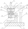
Fig. 1 is a structural representation of the present utility model.
The specific embodiment
As a kind of embodiment of the present utility model, as shown in Figure 1, a kind of novel cantilevered perforating die, comprise upper bolster 1, die shoe 2, die shank 3, punch 4, die 7, guide pin bushing 8 and guide pillar 9, punch 4 is fixedly connected on upper bolster 1 below by punch retainer 5, be provided with backing plate 6 between punch 4 and the upper bolster 1, punch 4 is provided with stripper 10, stripper 10 is provided with discharging spring 11, die 7 is fixedly connected on the corresponding position of die shoe 2 upper surfaces and punch 4 by L shaped die socket 13, in the present embodiment, die 7 is fixedly connected on the L shaped die socket 13 by screw, and L shaped die socket 13 is fixedly connected on die shoe 2 upper surfaces by screw.Punch 4 is outer to be socketed with blank holder 12, and the lower surface of blank holder 12 flushes with the lower surface of stripper 10, is provided with ball in guide pin bushing 8 and the gap that guide pillar 9 cooperates.
In the present embodiment, as preferably, upper bolster 1 and die shoe 2 adopt the Q235 steel plates to make.Guide pin bushing 8 and guide pillar 9 adopt 20 steel to make.
Claims (3)
1. novel cantilevered perforating die, comprise upper bolster, die shoe, die shank, punch, die, guide pin bushing and guide pillar, punch is fixedly connected on the upper bolster below by punch retainer, be provided with backing plate between punch and the upper bolster, punch is provided with stripper, stripper is provided with the discharging spring, die is fixedly connected on the die shoe upper surface position corresponding with punch by L shaped die socket, it is characterized in that: punch is socketed with blank holder outward, the lower surface of blank holder flushes with the lower surface of stripper, is provided with ball in guide pin bushing and the gap that guide pillar cooperates.
2. a kind of novel cantilevered perforating die according to claim 1 is characterized in that: upper bolster and die shoe adopt the Q235 steel plate to make.
3. a kind of novel cantilevered perforating die according to claim 1 and 2, it is characterized in that: guide pin bushing and guide pillar adopt 20 steel to make.
Priority Applications (1)
| Application Number | Priority Date | Filing Date | Title |
|---|---|---|---|
| CN2011200269698U CN202087680U (en) | 2011-01-27 | 2011-01-27 | Novel cantilever type punching die |
Applications Claiming Priority (1)
| Application Number | Priority Date | Filing Date | Title |
|---|---|---|---|
| CN2011200269698U CN202087680U (en) | 2011-01-27 | 2011-01-27 | Novel cantilever type punching die |
Publications (1)
| Publication Number | Publication Date |
|---|---|
| CN202087680U true CN202087680U (en) | 2011-12-28 |
Family
ID=45362780
Family Applications (1)
| Application Number | Title | Priority Date | Filing Date |
|---|---|---|---|
| CN2011200269698U Expired - Fee Related CN202087680U (en) | 2011-01-27 | 2011-01-27 | Novel cantilever type punching die |
Country Status (1)
| Country | Link |
|---|---|
| CN (1) | CN202087680U (en) |
Cited By (12)
| Publication number | Priority date | Publication date | Assignee | Title |
|---|---|---|---|---|
| CN102441615A (en) * | 2011-12-31 | 2012-05-09 | 苏州三维精密机械有限公司 | Die for forming side face of cup-shaped component |
| CN102847792A (en) * | 2012-08-21 | 2013-01-02 | 无锡美业机械制造有限公司 | Cantilever stamping mould for inner core of rubber shock-absorbing component |
| CN102873187A (en) * | 2012-08-21 | 2013-01-16 | 无锡美业机械制造有限公司 | Cantilever single-stamping die |
| CN103143606A (en) * | 2013-03-18 | 2013-06-12 | 苏州市瑞昌机电工程有限公司 | Cantilever stamping mechanism |
| CN103372598A (en) * | 2012-04-17 | 2013-10-30 | 成都玺汇科技有限公司 | Vertical punching die with internal male die |
| CN103495649A (en) * | 2013-09-03 | 2014-01-08 | 苏州市亿特隆电器有限公司 | One-time punching die of air conditioner compressor outer shell |
| CN103521594A (en) * | 2013-10-18 | 2014-01-22 | 芜湖环球汽车配件有限公司 | Lifting type sheet metal part punching device |
| CN103949536A (en) * | 2014-05-12 | 2014-07-30 | 盐城工业职业技术学院 | Spring type discharging side hole punching die |
| CN104338830A (en) * | 2014-11-26 | 2015-02-11 | 重庆市华青汽车配件有限公司 | Quick punching die |
| CN105583287A (en) * | 2014-11-17 | 2016-05-18 | 昌河飞机工业(集团)有限责任公司 | Pneumatic punching mechanism |
| CN106311873A (en) * | 2016-11-29 | 2017-01-11 | 安徽江淮汽车集团股份有限公司 | Hole-punching mold |
| CN107952869A (en) * | 2017-12-04 | 2018-04-24 | 哈尔滨建成集团有限公司 | A kind of cones wall cantilever type punching die tool |
-
2011
- 2011-01-27 CN CN2011200269698U patent/CN202087680U/en not_active Expired - Fee Related
Cited By (16)
| Publication number | Priority date | Publication date | Assignee | Title |
|---|---|---|---|---|
| CN102441615B (en) * | 2011-12-31 | 2014-04-23 | 苏州三维精密机械有限公司 | Die for forming side face of cup-shaped component |
| CN102441615A (en) * | 2011-12-31 | 2012-05-09 | 苏州三维精密机械有限公司 | Die for forming side face of cup-shaped component |
| CN103372598A (en) * | 2012-04-17 | 2013-10-30 | 成都玺汇科技有限公司 | Vertical punching die with internal male die |
| CN102847792B (en) * | 2012-08-21 | 2015-09-09 | 无锡美业机械制造有限公司 | The cantilever diel of rubber shock-absorbing element inner core |
| CN102847792A (en) * | 2012-08-21 | 2013-01-02 | 无锡美业机械制造有限公司 | Cantilever stamping mould for inner core of rubber shock-absorbing component |
| CN102873187A (en) * | 2012-08-21 | 2013-01-16 | 无锡美业机械制造有限公司 | Cantilever single-stamping die |
| CN102873187B (en) * | 2012-08-21 | 2015-09-23 | 无锡美业机械制造有限公司 | Cantilever single-stroke mould |
| CN103143606A (en) * | 2013-03-18 | 2013-06-12 | 苏州市瑞昌机电工程有限公司 | Cantilever stamping mechanism |
| CN103495649A (en) * | 2013-09-03 | 2014-01-08 | 苏州市亿特隆电器有限公司 | One-time punching die of air conditioner compressor outer shell |
| CN103521594A (en) * | 2013-10-18 | 2014-01-22 | 芜湖环球汽车配件有限公司 | Lifting type sheet metal part punching device |
| CN103949536A (en) * | 2014-05-12 | 2014-07-30 | 盐城工业职业技术学院 | Spring type discharging side hole punching die |
| CN105583287A (en) * | 2014-11-17 | 2016-05-18 | 昌河飞机工业(集团)有限责任公司 | Pneumatic punching mechanism |
| CN104338830A (en) * | 2014-11-26 | 2015-02-11 | 重庆市华青汽车配件有限公司 | Quick punching die |
| CN106311873A (en) * | 2016-11-29 | 2017-01-11 | 安徽江淮汽车集团股份有限公司 | Hole-punching mold |
| CN107952869A (en) * | 2017-12-04 | 2018-04-24 | 哈尔滨建成集团有限公司 | A kind of cones wall cantilever type punching die tool |
| CN107952869B (en) * | 2017-12-04 | 2023-11-07 | 中国兵器工业集团航空弹药研究院有限公司 | Cantilever type punching die for conical cylinder wall |
Similar Documents
| Publication | Publication Date | Title |
|---|---|---|
| CN202087680U (en) | Novel cantilever type punching die | |
| CN201979001U (en) | Novel inclined wedge type side hole stamping die | |
| CN202779384U (en) | Punching die with convex dies capable of moving horizontally | |
| CN201960043U (en) | Novel cantilever type bidirectional punching die | |
| CN201969774U (en) | Cantilever type bidirectional punching die | |
| CN100427239C (en) | Composite cold stamping mold | |
| CN203426248U (en) | Novel double-wedge punching die | |
| CN201969772U (en) | Novel wedge type side hole punching mold | |
| CN102303074A (en) | Side hole punching die | |
| CN201644669U (en) | Stripping structure for movable tapered wedge of non-vertical upward hole flanging and edge flanging female die | |
| CN202070656U (en) | Novel side hole punching mould | |
| CN202779417U (en) | Composite die with upper punch die | |
| CN202779499U (en) | Inverted blanking die with ejector | |
| CN202061980U (en) | Tapered wedge type side hole punching die | |
| CN204974784U (en) | A anti - extrusion die for producing long and thin dark blind hole aluminium alloy shell | |
| CN201385077Y (en) | Compound cold stamping die | |
| CN202070655U (en) | Novel side hole punching mould | |
| CN202910154U (en) | Punching device with movable female mold for square automobile pipe fitting | |
| CN203426247U (en) | Novel cantilever type piercing die | |
| CN201760503U (en) | Wheel spoke forming mold | |
| CN201511079U (en) | Stamping die for processing clutch diaphragm spring | |
| CN202506723U (en) | Oblique sliding block mechanism | |
| CN203304375U (en) | Novel inverted blanking die | |
| CN203044637U (en) | Forging precision thermal punching mold | |
| CN202779383U (en) | Symmetric hole piercing die for rotary workpieces |
Legal Events
| Date | Code | Title | Description |
|---|---|---|---|
| C14 | Grant of patent or utility model | ||
| GR01 | Patent grant | ||
| CF01 | Termination of patent right due to non-payment of annual fee |
Granted publication date: 20111228 Termination date: 20130127 |
|
| CF01 | Termination of patent right due to non-payment of annual fee |