CN201511079U - Stamping die for processing clutch diaphragm spring - Google Patents
Stamping die for processing clutch diaphragm spring Download PDFInfo
- Publication number
- CN201511079U CN201511079U CN2009202282702U CN200920228270U CN201511079U CN 201511079 U CN201511079 U CN 201511079U CN 2009202282702 U CN2009202282702 U CN 2009202282702U CN 200920228270 U CN200920228270 U CN 200920228270U CN 201511079 U CN201511079 U CN 201511079U
- Authority
- CN
- China
- Prior art keywords
- counterdie
- die
- diaphragm spring
- fixed plate
- upper mould
- Prior art date
- Legal status (The legal status is an assumption and is not a legal conclusion. Google has not performed a legal analysis and makes no representation as to the accuracy of the status listed.)
- Expired - Fee Related
Links
Images

Abstract
The utility model discloses a stamping die for processing a clutch diaphragm spring. Three waist-shaped circular holes, three small square slots and straight slots between the three waist-shaped circular holes and the three small square slots are integrally punched by utilizing the characteristics of stability and low possibility of damaging a die through the simple die stamping and the characteristic that the position of the product is easily ensured through integral die stamping. The stamping die can finish stamping to three groups of holes through one stroke, improve the production efficiency, reduce the burrs generated between the working procedures and ensure the small accumulated error.
Description
Technical field
The utility model relates to a kind of diel, particularly a kind of diel of processing clutch diaphragm spring.
Background technology
At present, the diel that domestic and international production heavy goods vehicles is used with diaphragm spring, a stroke of employing is only finished the simple punch die of an operation, be easy to generate the interface burr between the operation, the drift ratio is easier to pull, and the life-span is very short, and the position degree between the product fluting is restive.
Summary of the invention
For solving the above-mentioned problems in the prior art, the utility model provides a kind of diel of processing clutch diaphragm spring, adopt the characteristics of stablizing and be difficult for mold damage of simple punch die, adopt whole punch die to guarantee the characteristics of product space degree easily again, with three oval holes, three little square grooves and the whole punching of the straight trough between them.
The technical scheme that its technical problem that solves the utility model adopts is as follows: the diel of this processing clutch diaphragm spring, at least comprise the upper die and lower die that cooperatively interact, and place between the two location core, patrix comprises backing plate, upper mould fixed plate, screw, upper bolster, guide pin bushing, stripper and discharging screw, stripper is fixed on the upper mould fixed plate by the discharging screw, upper mould fixed plate is fixed on the upper bolster by screw, be provided with backing plate between upper mould fixed plate and upper bolster, guide pin bushing is loaded on upper bolster, be equiped with three drifts on the upper mould fixed plate, three drifts evenly distribute in a circumferential direction, counterdie comprises the counterdie hoop, guide pillar, pin, counterdie fixed head and die shoe, counterdie is fixed in die shoe by pin and counterdie hoop, be positioned at die shoe with the guide pillar of guide pin bushing coupling, the counterdie fixed head is provided with and three three slotted eyes that drift is corresponding.
Described slotted eye is made up of oval hole, square groove and straight trough, and the middle part of slotted eye is a straight trough, and the two ends of straight trough are respectively oval hole and square groove.
Compare with the one-shot mould of present use, the utility model provides stroke of diel of processing clutch diaphragm spring to finish the punching press in three groups of holes, can improve the efficient of production, reduces the burr that inter process produces, and has guaranteed that the meter error is little.
Description of drawings
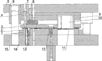
Fig. 1 is a structural representation of the present utility model.
Fig. 2 is a counterdie fixed head profile of the present utility model.
1. counterdies among the figure, 2. counterdie hoop, 3. stripper, 4. backing plate, 5. upper bolster, 6. guide pin bushing, 7. discharging screw, 8. screw, 9. upper mould fixed plate, 10. patrix, 11. counterdie fixed heads, 12. location cores, 13. pins, 14. guide pillar, 15. die shoes, 16. slotted eyes, 17. oval holes, 18. straight troughs, 19. square grooves.
The specific embodiment
Shown in Figure 1, the diel of the processing clutch diaphragm spring that the utility model provides, comprise the patrix 10 and the counterdie 1 that cooperatively interact, and place between the two location core 12, patrix 10 comprises backing plate 4, upper mould fixed plate 9, screw 8, upper bolster 5, guide pin bushing 6, in order to prevent that plate from blocking patrix 10, also comprise stripper 3 and discharging screw 7 on the patrix 10, stripper 3 is fixed on the upper mould fixed plate 9 by discharging screw 7, upper mould fixed plate 9 is fixed on the upper bolster 5 by screw 8,5 of upper mould fixed plate 9 and upper bolsters are provided with backing plate 4, guide pin bushing 6 is loaded on upper bolster 5, be equiped with three drifts on the upper mould fixed plate 9, three drifts evenly distribute in a circumferential direction, counterdie 1 comprises counterdie hoop 2, guide pillar 14, pin 13, counterdie fixed head 11 and die shoe 15, counterdie 1 is fixed in die shoe 15 by pin 13 and counterdie hoop 2, for patrix 10 and counterdie 1 can accurately be located, be positioned at die shoe 15 with the guide pillar 14 of guide pin bushing 6 couplings, counterdie fixed head 11 is provided with and three three slotted eyes 16 that drift is corresponding, slotted eye 16 is by oval hole 17, square groove 19 and straight trough 18 are formed, the middle part of slotted eye 16 is a straight trough 18, and the two ends of straight trough 18 are respectively oval hole 17 and square groove 19 (Fig. 2 shows).
During work, patrix moves downward, the location core enters and makes the blank location in the hole of going out in advance, and guide pillars and bushes cooperates makes patrix aim at counterdie, and keeps the gap, three solid punches carry out punching simultaneously, and blank is clamped patrix and with the patrix backhaul, blank is run into stripper and is pushed down, and blank is sent to again, carry out the punching campaign second time, the punching press in six groups of holes is once just finished in rotation like this.Compare with the one-shot mould of present use, stroke of this diel is finished the punching press in three groups of holes, has improved the efficient of producing, and has reduced the burr that inter process produces, and guarantees that cumulative errors are little.
Claims (2)
1. diel of processing clutch diaphragm spring, at least comprise the upper die and lower die that cooperatively interact, and place between the two location core, it is characterized in that: patrix comprises backing plate at least, upper mould fixed plate, screw, upper bolster, guide pin bushing, stripper and discharging screw, stripper is fixed on the upper mould fixed plate by the discharging screw, upper mould fixed plate is fixed on the upper bolster by screw, be provided with backing plate between upper mould fixed plate and upper bolster, guide pin bushing is installed on upper bolster, upper mould fixed plate is provided with three drifts, three drifts evenly distribute in a circumferential direction, counterdie comprises the counterdie hoop, guide pillar, pin, counterdie fixed head and die shoe, counterdie is fixed in die shoe by pin and counterdie hoop, and the guide pillar that mates with guide pin bushing is positioned at die shoe, and the counterdie fixed head is provided with and three three slotted eyes that drift is corresponding.
2. the diel of processing clutch diaphragm spring as claimed in claim 1 is characterized in that: slotted eye is made up of oval hole, square groove and straight trough, and the middle part of slotted eye is a straight trough, and the two ends of straight trough are respectively oval hole and square groove.
Priority Applications (1)
| Application Number | Priority Date | Filing Date | Title |
|---|---|---|---|
| CN2009202282702U CN201511079U (en) | 2009-09-21 | 2009-09-21 | Stamping die for processing clutch diaphragm spring |
Applications Claiming Priority (1)
| Application Number | Priority Date | Filing Date | Title |
|---|---|---|---|
| CN2009202282702U CN201511079U (en) | 2009-09-21 | 2009-09-21 | Stamping die for processing clutch diaphragm spring |
Publications (1)
| Publication Number | Publication Date |
|---|---|
| CN201511079U true CN201511079U (en) | 2010-06-23 |
Family
ID=42482476
Family Applications (1)
| Application Number | Title | Priority Date | Filing Date |
|---|---|---|---|
| CN2009202282702U Expired - Fee Related CN201511079U (en) | 2009-09-21 | 2009-09-21 | Stamping die for processing clutch diaphragm spring |
Country Status (1)
| Country | Link |
|---|---|
| CN (1) | CN201511079U (en) |
Cited By (5)
| Publication number | Priority date | Publication date | Assignee | Title |
|---|---|---|---|---|
| CN101966541A (en) * | 2010-08-17 | 2011-02-09 | 浙江龙华汽配制造有限公司 | Reinforcing structure of punching die for diaphragm spring |
| CN102284606A (en) * | 2011-08-05 | 2011-12-21 | 桂林福达股份有限公司 | Optimized stamping process for diaphragm spring with DST (direct solution treatment) structure |
| CN102380542A (en) * | 2011-10-19 | 2012-03-21 | 芜湖市恒联机电有限公司 | Punching die for machining and punching of mount support of front safety air bag |
| CN105268849A (en) * | 2015-10-17 | 2016-01-27 | 无为县鑫发盛汽车零部件有限公司 | Flanging forming die |
| CN106216490A (en) * | 2016-08-16 | 2016-12-14 | 湖北大帆汽车零部件有限公司 | A kind of diaphragm spring Sheet Metal Forming Technology |
-
2009
- 2009-09-21 CN CN2009202282702U patent/CN201511079U/en not_active Expired - Fee Related
Cited By (5)
| Publication number | Priority date | Publication date | Assignee | Title |
|---|---|---|---|---|
| CN101966541A (en) * | 2010-08-17 | 2011-02-09 | 浙江龙华汽配制造有限公司 | Reinforcing structure of punching die for diaphragm spring |
| CN102284606A (en) * | 2011-08-05 | 2011-12-21 | 桂林福达股份有限公司 | Optimized stamping process for diaphragm spring with DST (direct solution treatment) structure |
| CN102380542A (en) * | 2011-10-19 | 2012-03-21 | 芜湖市恒联机电有限公司 | Punching die for machining and punching of mount support of front safety air bag |
| CN105268849A (en) * | 2015-10-17 | 2016-01-27 | 无为县鑫发盛汽车零部件有限公司 | Flanging forming die |
| CN106216490A (en) * | 2016-08-16 | 2016-12-14 | 湖北大帆汽车零部件有限公司 | A kind of diaphragm spring Sheet Metal Forming Technology |
Similar Documents
| Publication | Publication Date | Title |
|---|---|---|
| CN202087680U (en) | Novel cantilever type punching die | |
| CN102672034B (en) | Die for fine punching of connecting bracket and fine punching method | |
| CN104368697B (en) | Reinforcing plate diel | |
| CN201511079U (en) | Stamping die for processing clutch diaphragm spring | |
| CN204974784U (en) | A anti - extrusion die for producing long and thin dark blind hole aluminium alloy shell | |
| CN204523999U (en) | The diel of underslung bearing flap | |
| CN201385077Y (en) | Compound cold stamping die | |
| CN204672829U (en) | A kind of for the U-shaped Bending Mould of bender | |
| CN201644616U (en) | Compound die for blanking and punching of automobile plate spring clips | |
| CN102019319A (en) | Mold structure of L-shaped connecting sheet for cable bridge | |
| CN103990695A (en) | Blanking and bending compound die | |
| CN204604456U (en) | A kind of die cutting die with floating location structure | |
| CN103111516B (en) | Boot-lid lock stiffener raising punching die | |
| CN203076432U (en) | Bending compound die | |
| CN203076437U (en) | Movable adjustable stamping die | |
| CN202239180U (en) | Continuous mold for shell | |
| CN201760488U (en) | Reinforcing structure of diaphragm spring notching die | |
| CN201862694U (en) | Stamping die for diaphragm spring | |
| CN203621214U (en) | Edge hole punching die for automobile clutch gland | |
| CN204220803U (en) | A kind of bottom plate of washing machine draws convex mold | |
| CN102950204A (en) | Punching and blanking mold of side plate of water tank | |
| CN203875184U (en) | Stamping die | |
| CN202894022U (en) | Punching and raising die for reinforced plate of back door windscreen wiper | |
| CN203418030U (en) | Intra-die feeding device | |
| CN209124718U (en) | A kind of reinforced pipe fitting metal parts molding die |
Legal Events
| Date | Code | Title | Description |
|---|---|---|---|
| C14 | Grant of patent or utility model | ||
| GR01 | Patent grant | ||
| CF01 | Termination of patent right due to non-payment of annual fee |
Granted publication date: 20100623 Termination date: 20140921 |
|
| EXPY | Termination of patent right or utility model |