CN202038845U - Overhead working platform with folding arms - Google Patents
Overhead working platform with folding arms Download PDFInfo
- Publication number
- CN202038845U CN202038845U CN2011201466392U CN201120146639U CN202038845U CN 202038845 U CN202038845 U CN 202038845U CN 2011201466392 U CN2011201466392 U CN 2011201466392U CN 201120146639 U CN201120146639 U CN 201120146639U CN 202038845 U CN202038845 U CN 202038845U
- Authority
- CN
- China
- Prior art keywords
- arm
- jib
- tail
- hinged
- balance
- Prior art date
- Legal status (The legal status is an assumption and is not a legal conclusion. Google has not performed a legal analysis and makes no representation as to the accuracy of the status listed.)
- Expired - Fee Related
Links
Images


Abstract
The utility model provides an overhead working platform with folding arms. The overhead working platform comprises three main parts, namely, a chassis part, a vehicle body part and a working part; the vehicle body part comprises an engine base, a slewing bearing and an arm frame, and the slewing bearing is mounted in the center of a vehicle frame of the chassis part; and the working part comprises a main arm, a tail arm, a flying arm and a working platform, a rocking lever is hinged between the tail arm and the arm frame, a flying arm connecting rod is hinged between the flying arm and the arm frame, a main frame oil cylinder is connected between the main arm and the arm frame, a tail arm oil cylinder is connected between the tail arm and a connecting plate, and a flying arm oil cylinder is connected between the tail arm and the flying arm connecting rod. The overhead working platform has the advantages of simple, compact and reasonable structure, improved working flexibility, convenience in operation, reliable performances, wide working range, strong adaptability to working environments, low pollution, remarkable energy-saving effect, good usability and convenience in maintenance.
Description
Technical field
The utility model relate to a kind of be used to transport the staff and work be provided to a kind of large-sized aerial work engineering mechanical device that specified altitude assignment is carried out operation, belong to the technical field of aloft work machinery.
Background technology
The high-altitude operation platform product category is various, differs from one another, and external starting has relatively early formed a very large industry, and has set up internationalization tissue (TC214).Domestic high-altitude operation platform relies on import substantially, independent research few.At present, domestic product generally all is Operation Van's line, and for the situation that only needs to work in the scope small region, Operation Van is the oil consumption height not only, and is seriously polluted, and floor area is big, makes field of application be restricted, especially in indoor situation.In addition, Operation Van also needs to develop special-purpose vehicle chassis, and technical risk increases.For solving above deficiency, be badly in need of compact size on the market, maneuverability, environmental pollution is little, can satisfy the novel high-altitude operation platform of the operating environment of indoor and outdoor simultaneously.
Summary of the invention
The utility model is at the problem that existing aerial platform exists, and provides that a kind of pollution is little, energy consumption is low, performance-oriented folding arm high-altitude operation platform, and this platform can satisfy various operating environments such as indoor and outdoor.
Folding arm high-altitude operation platform of the present utility model is realized by following technical solution:
The arm high-altitude operation platform be should fold, chassis portion, body portion and working portion three parts comprised; Chassis portion comprises vehicle frame, steering swivel system, change-speed box, suspension, drive axle and brake system, and steering swivel system, change-speed box, suspension, drive axle and brake system are installed on the vehicle frame, and the bottom of vehicle frame is equipped with wheel, and pivoting support also is installed on the vehicle frame; Body portion comprises engine bed, pivoting support and jib, and pivoting support is installed in the vehicle frame center of chassis portion, and engine bed is installed on the pivoting support, and jib is fixed on the engine bed; Working portion comprises principal arm, connecting panel, tail arm, middle hinge plate, fly jib and workplatform, be hinged with rocking bar between tail arm and the jib, be hinged with the fly jib connecting rod between fly jib and the jib, be connected with the principal arm oil cylinder between principal arm and the jib, the two ends of principal arm are hinged with jib and connecting panel respectively; Be connected with tail arm oil cylinder between tail arm and the connecting panel, the two ends of tail arm are hinged with connecting panel and middle hinge plate respectively; Be connected with the fly jib oil cylinder between tail arm and the fly jib connecting rod, the two ends of fly jib are hinged with middle hinge plate and workplatform respectively.
The parallel principal arm balance that is equipped with principal arm, the two ends of principal arm balance are hinged with jib and connecting panel respectively, the common principal arm levelling gear of forming a parallelogram sturcutre of jib, principal arm, principal arm balance and connecting panel.
The parallel tail arm balance that is equipped with the tail arm, the two ends of tail arm balance are hinged with connecting panel and middle hinge plate respectively, and tail arm balance, tail arm, connecting panel and middle hinge plate are formed the levelling gear of parallelogram sturcutre;
The parallel fly jib balance that is equipped with fly jib, the two ends of fly jib balance are hinged with middle hinge plate and workplatform respectively, and fly jib balance, fly jib, middle hinge plate and workplatform are formed the levelling gear of parallelogram sturcutre.
The utility model adopts modularization, simple in structure, compact and reasonable, both can select for use driving engine to realize outdoor working long hours, also can select storage battery zero-emission when reaching office work for use, zero requirement of polluting has been adopted pivoting support between chassis portion and the body portion, fixed underpan and body portion that can arbitrarily angled rotation are coupled together, improved the alerting ability of operation, easy to operate, dependable performance, scope of work is wide, the working environment adaptive capacity is strong, pollutes for a short time, and energy-saving effect is remarkable, ease for use is good simultaneously, maintenance, easy to maintenance.
Description of drawings
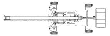
Fig. 1 is a Facad structure scheme drawing of the present utility model.
Fig. 2 is the left view of Fig. 1.
Fig. 3 is the birds-eye view of Fig. 1.
Fig. 4 is a guidance panel scheme drawing of the present utility model.
Among the figure, 1, counterweight, 2, wheel, 3, girder, 4, engine bed, 5, pivoting support, 6, jib bearing, 7, jib, 8, the principal arm oil cylinder, 9, principal arm cylinder support, 10, principal arm, 11, the principal arm balance, 12, connecting panel, 13, tail arm balance, 14, tail arm oil cylinder, 15, tail arm cylinder support, 16, the tail arm, 17, the fly jib cylinder support, 18, fly jib oil cylinder, 19, rocking bar, 20, middle hinge plate, 21, fly jib connecting rod, 22, the fly jib balance, 23, fly jib, 24, workplatform, 25, bogie truck, 26, turn to oil cylinder, 27, turn to oil cylinder seat, 28, crossbeam.
The specific embodiment
The structure of folding arm high-altitude operation platform of the present utility model such as Fig. 1, Fig. 2 and shown in Figure 3 comprise chassis portion, body portion and working portion three parts.
Chassis portion is the carrier of whole high-altitude operation platform, also is the carrier of traveling gear, is controlling the walking of car load.Chassis portion is the same with the chassis structure of existing self-propelled vehicle, comprises wheel 2, vehicle frame, steering swivel system, and vehicle frame is made of girder 3 and crossbeam 28, and is rectangular, and four angles of vehicle frame are connected with four wheels, constitutes the skeleton of car load.Steering swivel system comprises bogie truck 25 and turns to oil cylinder 27 that bogie truck 25 is connected with turning to oil cylinder 27, turns to oil cylinder 27 to be installed in and turns on the oil cylinder seat 26, turns to oil cylinder seat 26 to be installed on the vehicle frame.Change-speed box also is installed on the vehicle frame, suspension, drive axle and brake system, change-speed box is mainly used to control the speed when adjusting vehicle to run, to guarantee the stability and the safety of walking, suspension is connected vehicle body and transmits power and moment between wheel and the vehicle body with axletree elasticity, drive axle is realized increasing turning round, reduction of speed, change the transmission of torque direction, bear the power between road surface and the vehicle body, steering swivel system comprises and turns to oil cylinder and control cock, be used for changing or keeping the job platform travel direction, brake system is used to reduce the moving velocity of job platform or makes job platform rest on the original place.
Body portion is the bearing substrate that connects working portion and chassis portion, is made up of vitals such as engine bed 4, pivoting support 5, jibs 7.Pivoting support 5 is installed in the center of chassis portion rectangle frame, and pivoting support 5 is connecting body portion and chassis portion, realizes the rotation of job platform 360 degree.Engine bed 4 is installed on the pivoting support 5, and the rear end of engine bed 4 is provided with counterweight 1, and the front end of engine bed 4 is provided with jib bearing 6.Jib 7 is that the entire job flat-bed supports, one end of jib 7 is fixed on the jib bearing 6, the principal arm 10 of the other end and working portion is hinged, simultaneously between principal arm 10 and jib 7, be connected with principal arm oil cylinder 8, the cylinder body of principal arm oil cylinder 8 and jib 7 are hinged, principal arm cylinder support 9 on the piston rod of principal arm oil cylinder 8 and the principal arm 10 is hinged, and principal arm oil cylinder 8 is being controlled the stretching, extension and the retraction of principal arm 10, is used for changing the operation height of job platform.
Working portion mainly is made up of principal arm 10, tail arm 16, fly jib 23 and workplatform 24, and principal arm 10, tail arm 16 and fly jib 23 all are connected with levelling gear.Be hinged with rocking bar 19 between tail arm 16 and the jib 7, be hinged with fly jib connecting rod 21 between fly jib 23 and the jib 7.Principal arm balance 11 and principal arm 10 parallel installations, the two ends of principal arm balance 11 are hinged with jib 7 and connecting panel 12 respectively, the two ends of principal arm 10 are also hinged with jib 7 and connecting panel 12 respectively simultaneously, jib 7, principal arm 10, principal arm balance 11 and the connecting panel 12 common levelling gears of forming a parallelogram sturcutre, thereby guarantee at principal arm 10 when hinge turns to any angle, connecting panel 12 is unmodifieds with the relative angle of jib 7, this just provides guarantee for job platform maintenance level, has also improved the intensity and the stability of principal arm 10 simultaneously.Levelling gear with spline structure also uses on tail arm 16, tail arm balance 13 and the 16 parallel installations of tail arm, the two ends of tail arm balance 13 are hinged with connecting panel 12 and middle hinge plate 20 respectively, the two ends of tail arm 16 are also hinged with connecting panel 12 and middle hinge plate 20 respectively simultaneously, connecting panel 12, tail arm balance 13, tail arm 16, connecting panel 12 and middle hinge plate 20 are formed the levelling gear of parallelogram sturcutre.Be connected with tail arm oil cylinder 14 between connecting panel 12 and the tail arm 16, the cylinder body and the connecting panel 12 of tail arm oil cylinder 14 are hinged, the piston rod of tail arm oil cylinder 14 and the tail arm cylinder support 15 on the tail arm 16 are hinged, tail arm oil cylinder 14 is being controlled the stretching, extension and the retraction of tail arm 16, is used for changing the operation height of job platform.Fly jib 23 also adopts the levelling gear of same structure, fly jib balance 22 and fly jib 23 parallel installations, the two ends of fly jib balance 22 are hinged with middle hinge plate 20 and workplatform 24 respectively, the two ends of fly jib 23 are also hinged with middle hinge plate 20 and workplatform 24 respectively simultaneously, and fly jib balance 22, fly jib 23, middle hinge plate 20 and workplatform 24 are formed the levelling gear of parallelogram sturcutre.Be connected with fly jib oil cylinder 18 between tail arm 16 and the fly jib connecting rod 21, fly jib cylinder support 17 on the cylinder body of fly jib oil cylinder 18 and the tail arm 16 is hinged, the piston rod of fly jib oil cylinder 18 and fly jib connecting rod 21 are hinged, fly jib oil cylinder 18 is being controlled the stretching, extension and the retraction of fly jib 23, is used for changing the operation height of job platform.Workplatform 24 is frameworks that are welded into steel pipe, has both guaranteed intensity, the weight of the workplatform 24 that alleviates again.Fly jib oil cylinder 18 is connected with the quadrangle hinge that rocking bar 19 and fly jib connecting rod 21 are formed, and has enlarged the action radius of fly jib 23.
Working process of the present utility model is as follows:
When work, after earlier the battery isolator control on the vehicle body being opened, the staff earlier puts into needed device work after the workplatform 24, and the door from workplatform 24 sides enters into workplatform 24 again, and the door lock of workplatform 24 can be carried out next step operation after tight.As shown in Figure 4, one has 4 control lever on the guidance panel, and each control lever is in different positions just can make job platform 24 make different responses.Above first control lever (shown position from left to right) is shifted onto during the position, other three control lever can not be operated, at this moment principal arm oil cylinder 8 oil-feeds, make principal arm 10 rise, when principal arm 10 is raised to maximum position, No. 1 control lever self-return, at this moment just can operate other three control lever, this moment is if upwards promote the 2nd control lever, and 18 oil-feeds of fly jib oil cylinder, fly jib 23 is risen, when the position of fly jib 23 during, just reached the maximum horizontal scope of work of job platform, when fly jib reaches maximum height near level, No. 2 control lever self-returns, this moment, tail arm 16 stretched, when tail arm 16 is stretched over end position when promoting No. 1 control lever more left, all arms have all trailed, and have reached the maximum operation scope of this new type foldable arm job platform.In order to regulate the scope of work of job platform in horizontal surface, can promote control lever to the left or to the right No. 2, when promoting No. 2 control lever, pivoting support 5 is being with vehicle body and is being made gyroscopic movement with top, reaches needed job position.No. 3 control lever are as long as two operating positions up and down, are being controlled the moving direction of car load, and when upwards promoting No. 3 control lever, car load travels forward, and when pulling back No. 3 control lever, car load moves backward.No. 4 control lever is being controlled steering swivel system and brake system, when promoting No. 4 control lever left, and the car load left-handed turning, when promoting No. 4 control lever to the right, car load moves right, and when upwards promoting No. 4 control lever, realizes the car load braking.In the upper right side of guidance panel, a speed governing turn-knob switch is arranged, control the kinematic velocity of car load thus.According to the principle of ergonomics, will strive and stop button and be arranged on the lower right corner, when emergency case takes place, press scram button, can stop all motions of car load immediately, guarantee operating personnel's safety.
Claims (4)
1. a folding arm high-altitude operation platform comprises chassis portion, body portion and working portion three parts; Chassis portion comprises vehicle frame, steering swivel system, change-speed box, suspension, drive axle and brake system, steering swivel system, change-speed box, suspension, drive axle and brake system are installed on the vehicle frame, the bottom of vehicle frame is equipped with wheel, it is characterized in that: pivoting support also is installed on the vehicle frame; Body portion comprises engine bed, pivoting support and jib, and pivoting support is installed in the vehicle frame center of chassis portion, and engine bed is installed on the pivoting support, and jib is fixed on the engine bed; Working portion comprises principal arm, connecting panel, tail arm, middle hinge plate, fly jib and workplatform, be hinged with rocking bar between tail arm and the jib, be hinged with the fly jib connecting rod between fly jib and the jib, be connected with the principal arm oil cylinder between principal arm and the jib, the two ends of principal arm are hinged with jib and connecting panel respectively; Be connected with tail arm oil cylinder between tail arm and the connecting panel, the two ends of tail arm are hinged with connecting panel and middle hinge plate respectively; Be connected with the fly jib oil cylinder between tail arm and the fly jib connecting rod, the two ends of fly jib are hinged with middle hinge plate and workplatform respectively.
2. folding arm high-altitude operation platform according to claim 1, it is characterized in that: the parallel principal arm balance that is equipped with principal arm, the two ends of principal arm balance are hinged with jib and connecting panel respectively, the common principal arm levelling gear of forming a parallelogram sturcutre of jib, principal arm, principal arm balance and connecting panel.
3. folding arm high-altitude operation platform according to claim 1, it is characterized in that: the parallel tail arm balance that is equipped with the tail arm, the two ends of tail arm balance are hinged with connecting panel and middle hinge plate respectively, and tail arm balance, tail arm, connecting panel and middle hinge plate are formed the levelling gear of parallelogram sturcutre.
4. folding arm high-altitude operation platform according to claim 1, it is characterized in that: the parallel fly jib balance that is equipped with fly jib, the two ends of fly jib balance are hinged with middle hinge plate and workplatform respectively, and fly jib balance, fly jib, middle hinge plate and workplatform are formed the levelling gear of parallelogram sturcutre.
Priority Applications (1)
| Application Number | Priority Date | Filing Date | Title |
|---|---|---|---|
| CN2011201466392U CN202038845U (en) | 2011-05-10 | 2011-05-10 | Overhead working platform with folding arms |
Applications Claiming Priority (1)
| Application Number | Priority Date | Filing Date | Title |
|---|---|---|---|
| CN2011201466392U CN202038845U (en) | 2011-05-10 | 2011-05-10 | Overhead working platform with folding arms |
Publications (1)
| Publication Number | Publication Date |
|---|---|
| CN202038845U true CN202038845U (en) | 2011-11-16 |
Family
ID=44966303
Family Applications (1)
| Application Number | Title | Priority Date | Filing Date |
|---|---|---|---|
| CN2011201466392U Expired - Fee Related CN202038845U (en) | 2011-05-10 | 2011-05-10 | Overhead working platform with folding arms |
Country Status (1)
| Country | Link |
|---|---|
| CN (1) | CN202038845U (en) |
Cited By (7)
| Publication number | Priority date | Publication date | Assignee | Title |
|---|---|---|---|---|
| CN102530785A (en) * | 2011-12-30 | 2012-07-04 | 大连益利亚工程机械有限公司 | Multifunctional fly jib device for high-altitude work vehicle |
| CN104310244A (en) * | 2014-10-10 | 2015-01-28 | 无锡美特船舶设备有限公司 | Horizontal folding suspension arm |
| CN104692263A (en) * | 2015-02-28 | 2015-06-10 | 徐州徐工随车起重机有限公司 | Special track high-altitude operation device capable of covering whole section of tunnel |
| CN106089131A (en) * | 2015-04-28 | 2016-11-09 | 国民油井华高有限公司 | Winding pipe implanter processing equipment |
| CN106865460A (en) * | 2017-03-25 | 2017-06-20 | 山东交通学院 | A kind of cnc mechanism formula two-freedom crank arm type lifts robot |
| CN106943698A (en) * | 2017-04-28 | 2017-07-14 | 三汽车制造有限公司 | One kind forcible entry fire fighting truck |
| CN104793632B (en) * | 2014-01-16 | 2017-11-28 | 北京环境特性研究所 | A kind of two grades of precision wedge levellers of big stroke |
-
2011
- 2011-05-10 CN CN2011201466392U patent/CN202038845U/en not_active Expired - Fee Related
Cited By (9)
| Publication number | Priority date | Publication date | Assignee | Title |
|---|---|---|---|---|
| CN102530785A (en) * | 2011-12-30 | 2012-07-04 | 大连益利亚工程机械有限公司 | Multifunctional fly jib device for high-altitude work vehicle |
| CN102530785B (en) * | 2011-12-30 | 2014-07-23 | 大连益利亚工程机械有限公司 | Multifunctional fly jib device for high-altitude work vehicle |
| CN104793632B (en) * | 2014-01-16 | 2017-11-28 | 北京环境特性研究所 | A kind of two grades of precision wedge levellers of big stroke |
| CN104310244A (en) * | 2014-10-10 | 2015-01-28 | 无锡美特船舶设备有限公司 | Horizontal folding suspension arm |
| CN104692263A (en) * | 2015-02-28 | 2015-06-10 | 徐州徐工随车起重机有限公司 | Special track high-altitude operation device capable of covering whole section of tunnel |
| CN106089131A (en) * | 2015-04-28 | 2016-11-09 | 国民油井华高有限公司 | Winding pipe implanter processing equipment |
| CN106089131B (en) * | 2015-04-28 | 2018-12-28 | 国民油井华高有限公司 | Winding pipe implanter processing equipment |
| CN106865460A (en) * | 2017-03-25 | 2017-06-20 | 山东交通学院 | A kind of cnc mechanism formula two-freedom crank arm type lifts robot |
| CN106943698A (en) * | 2017-04-28 | 2017-07-14 | 三汽车制造有限公司 | One kind forcible entry fire fighting truck |
Similar Documents
| Publication | Publication Date | Title |
|---|---|---|
| CN202038845U (en) | Overhead working platform with folding arms | |
| CN206476703U (en) | Underbody raising mobile platform | |
| CN201873495U (en) | Overhead working truck | |
| CN202220069U (en) | Automatic gravity-center balance device of a high-position sorting vehicle | |
| CN204508739U (en) | Self-walking aerial working platform | |
| CN205601804U (en) | Kart takes lift translation ware | |
| CN203486786U (en) | Multi-gear electric-hydraulic dual-purposed truck crane | |
| CN102070097A (en) | Free mobile gate seat tower crane | |
| CN206156685U (en) | Dual -purpose platform truck of rail | |
| CN103832315A (en) | Road wrecker with sliding platform mechanism | |
| CN209506120U (en) | A kind of unmanned helicopter ground trailer | |
| CN108609197A (en) | A kind of ski type helicopter ground omnidirectional mobile device | |
| CN201151624Y (en) | Ground control mechanism for crane | |
| CN102180412B (en) | Rough-terrain wheeled crane | |
| CN203558813U (en) | Loading stacker | |
| CN202671168U (en) | Overhead platform working truck | |
| CN202483214U (en) | Simple three-dimensional garage | |
| CN205713127U (en) | The boom system of pump truck and pump truck | |
| CN108275584A (en) | One kind having multi-functional straight rail super large heavy-duty hoisting equipment | |
| CN107539929A (en) | A kind of low clearance can integral elevating omnidirectional intelligent family moving platform | |
| CN202935224U (en) | Road wrecker with sliding platform mechanism | |
| CN208731243U (en) | A kind of ski type helicopter ground omnidirectional mobile device | |
| CN106348203A (en) | Road-rail platform car and application method thereof | |
| CN202912647U (en) | Caterpillar band lifting mechanism used for caterpillar band self-walking-type aerial work platform | |
| CN112429674B (en) | Mixed pot transport vehicle |
Legal Events
| Date | Code | Title | Description |
|---|---|---|---|
| C14 | Grant of patent or utility model | ||
| GR01 | Patent grant | ||
| C17 | Cessation of patent right | ||
| CF01 | Termination of patent right due to non-payment of annual fee |
Granted publication date: 20111116 Termination date: 20140510 |