CN201922288U - Quick overhaul clamp for valves - Google Patents
Quick overhaul clamp for valves Download PDFInfo
- Publication number
- CN201922288U CN201922288U CN2010206669365U CN201020666936U CN201922288U CN 201922288 U CN201922288 U CN 201922288U CN 2010206669365 U CN2010206669365 U CN 2010206669365U CN 201020666936 U CN201020666936 U CN 201020666936U CN 201922288 U CN201922288 U CN 201922288U
- Authority
- CN
- China
- Prior art keywords
- flange
- threaded
- positioning sleeve
- clamp
- right flange
- Prior art date
- Legal status (The legal status is an assumption and is not a legal conclusion. Google has not performed a legal analysis and makes no representation as to the accuracy of the status listed.)
- Expired - Fee Related
Links
Images

Abstract
A quick overhaul clamp for valves relates to a clamp, and particularly relates to a clamp for quick centering for the repair of the seal surface of a valve. The quick overhaul clamp comprises a left flange connected with the main shaft of the lathe, wherein a right flange is arranged on the right side of the left flange, at least two supporting rods are arranged between the left flange and the right flange, the left ends of all the supporting rods are in threaded connection with the left flange respectively, and the right ends of all the supporting rods are in threaded connection with the right flange through nuts respectively; a threaded rod is in threaded connection to the left flange, and one end of the threaded rod, which faces to the right flange, is in threaded connection with a compression nut; and an axially mounting hole is formed on the right flange, a positioning sleeve is arranged inside the axially mounting hole, and the positioning sleeve and the threaded rod are coaxially arranged. During the process of centering, the right end of a valve body is mounted inside the positioning sleeve, and the left side of the valve body is fixed through the compression nut. Therefore, convenient and quick centering can be achieved.
Description
Technical field
The utility model relates to a kind of anchor clamps, particularly relates to valve sealing face is repaired the anchor clamps that carry out quick centering.
Background technology
General valve is after using after a while, and sealing surface all can have damage in various degree, uses traditional method will be on engine lathe the turning sealing surface, the very difficult centering of processing sealing surface.
Summary of the invention
The purpose of this utility model is in order to overcome the deficiencies in the prior art, to provide a kind of valve of centering easily and fast to overhaul anchor clamps fast.
The purpose of this utility model is achieved in that valve overhauls anchor clamps fast, comprise the left flange that can be connected with lathe spindle, the right side of described left flange is provided with right flange, at least two cramp bars are set between left side flange and the right flange, the left end of every cramp bar is threaded with left flange respectively, and the right-hand member of every cramp bar is fixedlyed connected with right flange by nut respectively; The screw rod that also is threaded on the described left flange, the threaded one end towards right flange on the screw rod connects clamp nut; On the described right flange axial installing hole is set, axially positioning sleeve is set, positioning sleeve and described screw coaxial setting in the installing hole.
During centering, the right-hand member of valve body is installed in the positioning sleeve, the clamp nut that passes on left of valve body is fixed, and just can realize centering.Utilize the utility model, 1., can realize the centering of sealing surface very easily as long as repair the interior hole dimension that the middle processing excircles of valve body is determined interchangeable positioning sleeve according to need; 2. change positioning sleeve, can also process valve of the same type but that size differs not too big and process; 3. this design is the most outstanding is also advantageous in that it can reuse, avoided can not the secondary clamping drawback.
In order to prevent that clamp nut from moving backward, fastening screw nut in addition is threaded on the described screw rod.
In order to cooperate Y-valve door (once-through type, middle afterbody have centre bore), clamp nut is fixedly connected top away from a side of left flange.The adjustable clamp nut of afterbody be processed into 60 ° top, can realize that equally quick centering and positioning accuracy are higher.
Description of drawings
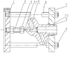
Fig. 1 is a kind of structural representation of the present utility model.
Fig. 2 is an another kind of structural representation of the present utility model.
The specific embodiment
As shown in Figure 1, for valve overhauls anchor clamps fast, comprise the left flange 1 that can be connected with lathe spindle, the right side of left side flange 1 is provided with right flange 7, between left side flange 1 and the right flange 7 four cramp bars 6 are set, the left end of every cramp bar 6 is threaded with left flange 1 respectively, and the right-hand member of every cramp bar 6 is fixedlyed connected with right flange 7 by nut 9 respectively.The left side screw rod 2 that also is threaded on the flange 1, the threaded one end towards right flange 7 on the screw rod 2 connects clamp nut 4, and fastening screw nut 3 also is threaded on the screw rod 2.On the right flange 7 axial installing hole 7-1 is set, axially is equipped with interchangeable positioning sleeve 8, positioning sleeve 8 and screw rod 2 coaxial settings in the installing hole 7-1.The right-hand member of valve body 5 is set in the positioning sleeve 8, and left end is tightened by clamp nut 4.
As shown in Figure 2, in order to cooperate the Y-valve door, clamp nut 4 is away from the fixedly connected top 4-1 of a side of left flange 1.
Claims (3)
1. valve overhauls anchor clamps fast, it is characterized in that: comprise the left flange that can be connected with lathe spindle, the right side of described left flange is provided with right flange, at least two cramp bars are set between left side flange and the right flange, the left end of every cramp bar is threaded with left flange respectively, and the right-hand member of every cramp bar is fixedlyed connected with right flange by nut respectively; The screw rod that also is threaded on the described left flange, the threaded one end towards right flange on the screw rod connects clamp nut; On the described right flange axial installing hole is set, axially positioning sleeve is set, positioning sleeve and described screw coaxial setting in the installing hole.
2. valve according to claim 1 overhauls anchor clamps fast, it is characterized in that: fastening screw nut also is threaded on the described screw rod.
3. valve according to claim 1 overhauls anchor clamps fast, it is characterized in that: described clamp nut is fixedly connected top away from a side of left flange.
Priority Applications (1)
| Application Number | Priority Date | Filing Date | Title |
|---|---|---|---|
| CN2010206669365U CN201922288U (en) | 2010-12-20 | 2010-12-20 | Quick overhaul clamp for valves |
Applications Claiming Priority (1)
| Application Number | Priority Date | Filing Date | Title |
|---|---|---|---|
| CN2010206669365U CN201922288U (en) | 2010-12-20 | 2010-12-20 | Quick overhaul clamp for valves |
Publications (1)
| Publication Number | Publication Date |
|---|---|
| CN201922288U true CN201922288U (en) | 2011-08-10 |
Family
ID=44426157
Family Applications (1)
| Application Number | Title | Priority Date | Filing Date |
|---|---|---|---|
| CN2010206669365U Expired - Fee Related CN201922288U (en) | 2010-12-20 | 2010-12-20 | Quick overhaul clamp for valves |
Country Status (1)
| Country | Link |
|---|---|
| CN (1) | CN201922288U (en) |
Cited By (2)
| Publication number | Priority date | Publication date | Assignee | Title |
|---|---|---|---|---|
| CN113145898A (en) * | 2021-02-19 | 2021-07-23 | 江苏科技大学 | Clamping device for drill clamp of rocker arm support of diesel engine |
| CN114406734A (en) * | 2022-01-21 | 2022-04-29 | 北京市阀门总厂股份有限公司 | Tool and equipment for processing valve body middle opening |
-
2010
- 2010-12-20 CN CN2010206669365U patent/CN201922288U/en not_active Expired - Fee Related
Cited By (3)
| Publication number | Priority date | Publication date | Assignee | Title |
|---|---|---|---|---|
| CN113145898A (en) * | 2021-02-19 | 2021-07-23 | 江苏科技大学 | Clamping device for drill clamp of rocker arm support of diesel engine |
| CN114406734A (en) * | 2022-01-21 | 2022-04-29 | 北京市阀门总厂股份有限公司 | Tool and equipment for processing valve body middle opening |
| CN114406734B (en) * | 2022-01-21 | 2023-07-04 | 北京市阀门总厂股份有限公司 | Frock and equipment are used in valve body middle-mouth processing |
Similar Documents
| Publication | Publication Date | Title |
|---|---|---|
| CN204603354U (en) | Thin-walled fixture for processing excircle of barrel-shaped parts | |
| CN202114495U (en) | Rigid tooling for machining slender workpieces | |
| CN203610707U (en) | Special fixture for turning excircle of thin-wall cylinder body | |
| CN204639725U (en) | A kind of quick position, clamping, anti-deformation fixture of processing thin-walled bend pipe end | |
| CN201922288U (en) | Quick overhaul clamp for valves | |
| CN205437921U (en) | Quick change profile shaft stomidium adds clamping apparatus | |
| CN202062245U (en) | Adjustable positioning device for turning cylinder body | |
| CN201940842U (en) | Lathe processing device with thin-walled guide sleeve | |
| CN103350261A (en) | Gear hobbing clamp oriented by flat position of gear and installation and debugging method | |
| CN203712368U (en) | Sheet-type component inner hole turning clamp | |
| CN103084673A (en) | Double-end pipe joint coaxial positioning turning clamp | |
| CN203380387U (en) | Fine turning fixture | |
| CN103072018A (en) | Turning device for main valve body of special ball valve | |
| CN201736054U (en) | Automatic clamping device of internal hole of front end cover of turned starting motor | |
| CN109249069B (en) | Step cylinder milling fixture | |
| CN201338105Y (en) | Jig for turning streamline profile | |
| CN208450639U (en) | A kind of expansion sleeve type turning clamp for thin-walled parts | |
| CN103624575A (en) | Automobile steering knuckle shell clamp | |
| CN207479645U (en) | A kind of cone vehicle internal clamp | |
| CN203304954U (en) | Drilling pneumatic tool | |
| CN202317798U (en) | Clamp disk | |
| CN203495273U (en) | Spalling prevention centering expansive force clamp | |
| CN203401166U (en) | Quick-change clamp for sleeve type insertion spline | |
| CN203541760U (en) | Expansion sleeve type gear grinding clamp | |
| CN102490039A (en) | Internal hole clamp of automobile generator casing and method for preventing deformation |
Legal Events
| Date | Code | Title | Description |
|---|---|---|---|
| C14 | Grant of patent or utility model | ||
| GR01 | Patent grant | ||
| CF01 | Termination of patent right due to non-payment of annual fee |
Granted publication date: 20110810 Termination date: 20141220 |
|
| EXPY | Termination of patent right or utility model |