CN201848609U - Device for machining ultra-large gear - Google Patents
Device for machining ultra-large gear Download PDFInfo
- Publication number
- CN201848609U CN201848609U CN201020612419XU CN201020612419U CN201848609U CN 201848609 U CN201848609 U CN 201848609U CN 201020612419X U CN201020612419X U CN 201020612419XU CN 201020612419 U CN201020612419 U CN 201020612419U CN 201848609 U CN201848609 U CN 201848609U
- Authority
- CN
- China
- Prior art keywords
- lathe bed
- main shaft
- milling cutter
- gear wheel
- chuck
- Prior art date
- Legal status (The legal status is an assumption and is not a legal conclusion. Google has not performed a legal analysis and makes no representation as to the accuracy of the status listed.)
- Expired - Fee Related
Links
- 238000003754 machining Methods 0.000 title abstract description 4
- 238000003801 milling Methods 0.000 claims abstract description 18
- 239000000446 fuel Substances 0.000 claims description 5
- 238000000034 method Methods 0.000 claims description 5
- 239000003921 oil Substances 0.000 description 5
- 239000010720 hydraulic oil Substances 0.000 description 2
- TVEXGJYMHHTVKP-UHFFFAOYSA-N 6-oxabicyclo[3.2.1]oct-3-en-7-one Chemical compound C1C2C(=O)OC1C=CC2 TVEXGJYMHHTVKP-UHFFFAOYSA-N 0.000 description 1
- 229910000851 Alloy steel Inorganic materials 0.000 description 1
- 230000009286 beneficial effect Effects 0.000 description 1
- 230000015572 biosynthetic process Effects 0.000 description 1
- 238000010586 diagram Methods 0.000 description 1
- 238000005516 engineering process Methods 0.000 description 1
- 230000001050 lubricating effect Effects 0.000 description 1
- 239000000155 melt Substances 0.000 description 1
- 238000002360 preparation method Methods 0.000 description 1
Images


Landscapes
- Turning (AREA)
Abstract
The utility model relates to an improvement on a gear machining device, and provides a device for machining an ultra-large gear with the diameter over 5 meters. The device comprises a longitudinal lathe bed and a transverse lathe bed, and is characterized in that a main shaft box is arranged on the longitudinal lathe bed, a clamping chuck is arranged at one end of the main shaft of the main shaft box, the other end of the main shaft is connected with a motor through a worm gear, a support base corresponding to the main shaft is arranged on the longitudinal lathe bed, a conical support is arranged on the main shaft and the clamping chuck, a milling cutter box is arranged on the guide rail of the transverse lathe bed, and a lead screw of the milling cutter box is connected with a differential box.
Description
Technical field
The utility model relates to process the improvement of geared system structure, is more suitable for processing the gear wheel device of the big modulus of heavily loaded ultra-large type.
Background technology
The equipment of existing processing gear wheel is exactly five meters gear-hobbing machines (vertical processing), but it is for processing heavily loaded diameter greater than 5 meters, modulus is just very difficult greater than the gear wheel more than 36, the problem of this equipment processing gear wheel is: 1, five meters gear-hobbing machines (circle) workbench diameter is 4 meters, and is just very difficult for the large gear that is installed greater than 5 meters.
Process gear wheel on 5 meters gear-hobbing machines, not only the rigidity of lathe is very poor but also cost is also very high.
Summary of the invention
The utility model is exactly at the problems referred to above, and a kind of processing ultra-large type gear wheel device of processing gear wheel more than 5 meters is provided.
In order to realize above-mentioned purpose of the present utility model, the utility model adopts following technical scheme, the utility model comprises vertical lathe bed, horizontal lathe bed, the vertical lathe bed of its structural feature is provided with main spindle box, and main shaft one end of main spindle box is a chuck, and the main shaft other end links to each other with motor by worm gear, supporting seat with the main shaft correspondence is arranged on vertical lathe bed, main shaft and chuck are provided with conical supports, and laterally the guide rail of lathe bed is provided with the milling cutter case, and the leading screw of milling cutter case links to each other with differential case.
The beneficial effects of the utility model: because the vertical lathe bed of the utility model is provided with main spindle box, main shaft one end of main spindle box is a chuck, the main shaft other end links to each other with motor by worm gear, supporting seat with the main shaft correspondence is arranged on vertical lathe bed, main shaft and chuck are provided with conical supports, laterally the guide rail of lathe bed is provided with the milling cutter case, and the leading screw of milling cutter case links to each other with differential case; Can process diameter phi≤6800 millimeter, facewidth B≤800 millimeter, β≤15 °, the steel alloy gear wheel of weight Q≤30 ton, and machining accuracy has reached requirement.
Description of drawings
Fig. 1 is a vertical view of the present utility model.
Fig. 2 is the A-A cutaway view of Fig. 1.
Fig. 3 is the B-B cutaway view of Fig. 1.
Fig. 4 is the structural representation of conical supports.
Fig. 5 is the bearing portions structural representation.
Fig. 6 is the vertical view of Fig. 5.
Fig. 7 is the dependency structure schematic diagram of the same fixture of processed gear, roller devices.
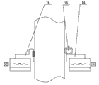
Fig. 8 is that main shaft is with the structural representation between the bearing.
In the accompanying drawing, 1 is worm gear, and 2 is motor, and 3 is vertical lathe bed, 4 is main spindle box, and 5 is chuck, and 6 is conical supports, and 7 is main shaft, 8 is supporting seat, and 9 is differential case, and 10 is leading screw, 11 is the milling cutter case, and 12 is guide rail, and 13 is horizontal lathe bed, 14 is roller devices, and 15 is roller, and 16 is fixture, 17 is bearing, and 18 is fuel feed hole, and 19 is oil pocket.
The specific embodiment
The utility model comprises vertical lathe bed 3, horizontal lathe bed 13, vertically lathe bed 3 is provided with main spindle box 4, main shaft 7 one ends of main spindle box 4 are chuck 5, main shaft 7 other ends link to each other with motor 2 by worm gear 1, supporting seat 8 with main shaft 7 correspondences is arranged on vertical lathe bed 3, main shaft 7 and chuck 5 are provided with conical supports 6, and laterally the guide rail 12 of lathe bed 13 is provided with milling cutter case 11, and the leading screw 10 of milling cutter case 11 links to each other with differential case 9.
For improving the stability of cutting, the horizontal lathe bed 13 of a side of the milling cutter of milling cutter case 11 is provided with fixture 16, and the horizontal lathe bed of opposite side is provided with roller devices 14; Fixture 16 is that the side with processed gear wheel contacts all the time, and motionless synchronously; The roller 15 of roller devices 14 contacts with the side of processed gear wheel all the time, and rotates with the motion of processed gear wheel; Purpose is to accomplish to make milling cutter gear wheel in working angles to rotate freely stable cutting.
In bearing 17 oil pockets 19 of main shaft 7, be provided with fuel feed hole 18; Fuel feed hole 18 can link to each other with handlance; Because gear wheel is overweight (if comprising that chuck 5, main shaft 7, worm gear 1 can reach about more than 40 tons), be difficult to form oil film, before starting with handlance squeeze into hydraulic oils in the middle of bearing 17 oil pockets 19 form the roof pressure district with main shaft 7(together with the gear wheel workpiece) hold up 0.04-0.09 millimeter, easily start revolution then, thereby improved lubricating condition, and reached the purpose that unloads and reduce staring torque, respond well.
Below in conjunction with a description of drawings course of action of the present utility model: hemicone (half of conical supports 6) is contained on the chuck 5, treat that the gear wheel workpiece puts into behind the melt pit in place supporting seat 8 again, second half cone handle is combined into one, treat again the gear wheel workpiece to be packed into after these preparations are finished on the chuck 5, before main shaft 7 drives chuck 5 revolutions, earlier the hydraulic oil of squeezing into handlance is with (formation oil film) after 0.04-0.09 millimeter of main shaft 7 jack-up, the gear wheel workpiece is carried out the centering chucking, when adjusting milling cutter case 11, can process with respect to the milling cutter position of gear wheel workpiece.
Claims (3)
1. process ultra-large type gear wheel device for one kind, comprise vertical lathe bed (3), horizontal lathe bed (13), it is characterized in that vertical lathe bed (3) is provided with main spindle box (4), main shaft (7) one ends of main spindle box (4) are chuck (5), main shaft (7) other end links to each other by the same motor of worm gear (1) (2), the supporting seat (8) that same main shaft (7) is corresponding is arranged on vertical lathe bed (3), main shaft (7) and chuck (5) are provided with conical supports (6), laterally the guide rail (12) of lathe bed (13) is provided with milling cutter case (11), and the leading screw (10) of milling cutter case (11) links to each other with differential case (9).
2. a kind of processing ultra-large type gear wheel device according to claim 1, the horizontal lathe bed (13) of a side that it is characterized in that the milling cutter of milling cutter case (11) is provided with fixture (16), and the horizontal lathe bed of opposite side is provided with roller devices (14).
3. a kind of processing ultra-large type gear wheel device according to claim 1 is characterized in that being provided with fuel feed hole (18) in bearing (17) oil pocket (19) of main shaft (7), and fuel feed hole (18) links to each other with handlance.
Priority Applications (1)
| Application Number | Priority Date | Filing Date | Title |
|---|---|---|---|
| CN201020612419XU CN201848609U (en) | 2010-11-18 | 2010-11-18 | Device for machining ultra-large gear |
Applications Claiming Priority (1)
| Application Number | Priority Date | Filing Date | Title |
|---|---|---|---|
| CN201020612419XU CN201848609U (en) | 2010-11-18 | 2010-11-18 | Device for machining ultra-large gear |
Publications (1)
| Publication Number | Publication Date |
|---|---|
| CN201848609U true CN201848609U (en) | 2011-06-01 |
Family
ID=44091022
Family Applications (1)
| Application Number | Title | Priority Date | Filing Date |
|---|---|---|---|
| CN201020612419XU Expired - Fee Related CN201848609U (en) | 2010-11-18 | 2010-11-18 | Device for machining ultra-large gear |
Country Status (1)
| Country | Link |
|---|---|
| CN (1) | CN201848609U (en) |
Cited By (2)
| Publication number | Priority date | Publication date | Assignee | Title |
|---|---|---|---|---|
| CN110640232A (en) * | 2019-10-14 | 2020-01-03 | 长丰吾道智能光电科技有限公司 | Gear ring clamping machining method |
| CN110640233A (en) * | 2019-10-14 | 2020-01-03 | 长丰吾道智能光电科技有限公司 | Outer gear ring processing device |
-
2010
- 2010-11-18 CN CN201020612419XU patent/CN201848609U/en not_active Expired - Fee Related
Cited By (2)
| Publication number | Priority date | Publication date | Assignee | Title |
|---|---|---|---|---|
| CN110640232A (en) * | 2019-10-14 | 2020-01-03 | 长丰吾道智能光电科技有限公司 | Gear ring clamping machining method |
| CN110640233A (en) * | 2019-10-14 | 2020-01-03 | 长丰吾道智能光电科技有限公司 | Outer gear ring processing device |
Similar Documents
| Publication | Publication Date | Title |
|---|---|---|
| CN202752651U (en) | Special boring machine for machining super-long holes | |
| CN201744877U (en) | Automatic positioning frame | |
| CN201848609U (en) | Device for machining ultra-large gear | |
| CN205324913U (en) | Screw, nut hexagonal mill system instrument | |
| CN202877559U (en) | Cutter frame structure of vertical lathe | |
| CN202572013U (en) | Centering device in boring sleeve and milling machine rough machining of steam turbine stator part | |
| CN103659356A (en) | Tool manufacturing method special for radiant tube machining | |
| CN203282178U (en) | Large vertical type high-speed numerically controlled lathe | |
| CN202922305U (en) | Transmission mechanism for vertical lathe | |
| CN204053749U (en) | Synchro converter ring conical surface facing-up frock | |
| CN202684537U (en) | Automatic positioning frame | |
| CN203437682U (en) | Double-drill-bit horizontal drilling machine | |
| CN105195832A (en) | Electric polishing machine tool | |
| CN204338967U (en) | Motor bearings lid oil-hole drill die device | |
| CN102921972A (en) | Knife rest structure of vertical lathe | |
| CN203853590U (en) | Special machine for boring bar cage | |
| CN203804269U (en) | Deep processing device of boring machine or milling machine | |
| CN203972912U (en) | A kind of lathe of processing high speed roller endoporus | |
| CN203751686U (en) | Turning-milling integrated lathe for machining shaft workpiece | |
| CN203380674U (en) | Double XZ-direction machine tool | |
| CN202180210U (en) | Tailstock ejector device used for vertical lathe | |
| CN202639376U (en) | Automatic positioning frame | |
| CN201544315U (en) | Special machining device for internal thread of bamboo-wood materials | |
| CN204657480U (en) | A kind of bearing roller processing unit (plant) | |
| CN208230891U (en) | It is a kind of to bore porous radial drilling machine simultaneously |
Legal Events
| Date | Code | Title | Description |
|---|---|---|---|
| C14 | Grant of patent or utility model | ||
| GR01 | Patent grant | ||
| CF01 | Termination of patent right due to non-payment of annual fee |
Granted publication date: 20110601 Termination date: 20151118 |
|
| EXPY | Termination of patent right or utility model |