CN201848589U - Small-size squaring machine work feeder capable of being used for processing large-size parts - Google Patents
Small-size squaring machine work feeder capable of being used for processing large-size parts Download PDFInfo
- Publication number
- CN201848589U CN201848589U CN 201020558387 CN201020558387U CN201848589U CN 201848589 U CN201848589 U CN 201848589U CN 201020558387 CN201020558387 CN 201020558387 CN 201020558387 U CN201020558387 U CN 201020558387U CN 201848589 U CN201848589 U CN 201848589U
- Authority
- CN
- China
- Prior art keywords
- size
- small
- slide block
- shaping machine
- planing tool
- Prior art date
- Legal status (The legal status is an assumption and is not a legal conclusion. Google has not performed a legal analysis and makes no representation as to the accuracy of the status listed.)
- Expired - Fee Related
Links
- 238000007493 shaping process Methods 0.000 claims description 23
- 241000282414 Homo sapiens Species 0.000 claims description 10
- 238000003754 machining Methods 0.000 claims description 9
- 238000005520 cutting process Methods 0.000 abstract description 6
- 238000003801 milling Methods 0.000 abstract description 6
- 238000000034 method Methods 0.000 description 2
- 238000005516 engineering process Methods 0.000 description 1
- 238000004519 manufacturing process Methods 0.000 description 1
- 230000001105 regulatory effect Effects 0.000 description 1
Images
Landscapes
- Turning (AREA)
Abstract
The utility model provides a small-size squaring machine work feeder capable of being used for processing large-size parts, which has the advantages that a small-size squaring machine can be used for processing large-size parts, and the work feeder has a simple structure and can be used for carrying out key slot and square hole cutting processing on large-size or ultra-large-size parts, so the purchasing of large-size processing equipment such as large-size or ultra-large-size plane milling and boring machines and the like is avoided, and the equipment cost is saved. The work feeder comprises a machine body of the squaring machine, a slide pillow and a work table, wherein the slide pillow is arranged on the machine body. The utility model is characterized in that a feed slide groove is arranged on the work table, a slide block is embedded in the feed slide groove and is connected with the slide pillow through a pulling rod, the front end part of the slide block is provided with a planing cutter rod, and the end part of the planing cutter rod is provided with a planing cutter.
Description
Technical field
The utility model relates to the planer processing technique field, is specially a kind of feed arrangement of small-sized shaping machine that can the machining large parts.
Background technology
General shaping machine is used for plane, groove or the dovetail face on the middle-size and small-size workpiece of planing operation more, it mainly drives the reciprocal cutting main motion that knife rest on it is made straight line by the ram on the lathe bed, planing machine platen can move upper and lower, left and right, thereby the workpiece of finishing being fixed on the workbench is a planing operation with respect to the feed campaign of planing tool.Processing for keyway, square hole on large-scale or the ultra-large type parts, large-scale or the superhuge plane milling and boring machine of many employings, because it is large-scale or the ultra-large type plane milling and boring machine takes up room greatly, equipment cost is high, and it is lower for its utilization rate large-scale or the ultra-large type plane milling and boring machine of middle-size and small-size processing enterprise, and owing to be subjected to volume restrictions large-scale or the ultra-large type parts, general small-sized shaping machine can't be processed large parts again.
Summary of the invention
At the problems referred to above, the utility model provides a kind of feed arrangement that can be used for the small-sized shaping machine of machining large parts, it makes the small-sized shaping machine can the machining large parts, it is simple in structure, can carry out the machining of keyway, square hole to large-scale or ultra-large type parts, can remove from like this and purchase large-scale or large-sized processing equipment such as ultra-large type plane milling and boring machine, save equipment cost.
Its technical scheme is such, it comprises lathe bed, ram and the workbench of shaping machine, described ram is installed on the described lathe bed, it is characterized in that: the feed chute is installed on the described workbench, be embedded with slide block in the described feed chute, described slide block is connected by dead man with ram, and described slip front portion is equipped with planing tool bar, and described planing tool bar end is equipped with planing tool.
It is further characterized in that: described dead man upper end by the shaping machine cutter holder be fixed in described ram leading section, its lower end is plugged in the elongated slot of described slide block; Described planing tool bar is plugged in the hole slot of described slide block end and passes through bolting.
It is simple in structure for the utility model, because large-scale or ultra-large type parts to be processed are positioned over small-sized shaping machine outside, so its process can not be subjected to the influence of workpiece size, enterprise need not to dispose large-scale or the ultra-large type plane milling and boring machine can be finished large-scale, the processing of ultra-large type parts, it is connected the ram of shaping machine by dead man with slide block on being installed on workbench, slip front is equipped with planing tool by planing tool bar, make identical reciprocal cutting movement by the straight reciprocating motion drive slide block of ram and the planing tool of slip front, thereby realize large-scale or ultra-large type parts keyway, the processing of square hole, it can reduce the equipment purchasing cost, improve the utilization rate of small-sized shaping machine simultaneously, reduce production costs.
Description of drawings
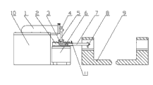
Fig. 1 is a kind of small-sized shaping machine structural representation that can the machining large parts of the present utility model.
The specific embodiment
See Fig. 1, the utility model device is installed on shaping machine, shaping machine comprises lathe bed 10, ram 1 and workbench 6, ram 1 is installed on the lathe bed 10, feed chute 2 is installed on the workbench 10, is embedded with slide block 3 in the feed chute 2, slide block 3 is connected by dead man 5 with ram 1, slide block 3 leading sections are equipped with planing tool bar 7, and planing tool bar 7 ends are equipped with planing tool 8.Dead man 5 upper ends by shaping machine cutter holder 4 be fixed in ram 1 leading section, its lower end is plugged in the elongated slot of slide block 3; It is interior also fixing by bolt 11 that planing tool bar 7 is plugged in the hole slot of slide block 3 ends.
During work, large-scale or ultra-large workpiece 9 to be processed is positioned over the outside portion of shaping machine, position according to large-scale or ultra-large workpiece position adjustments workbench 6 to be processed, shaping machine workbench 6 can be done, down, a left side, moving of right four direction, when regulating on the shaping machine workbench 6, during following vertical position, should regulate dead man 5 simultaneously, guarantee that dead man 5 is plugged in the slide block 3 all the time, thereby guarantee planing tool bar 7 with and on planing tool 8 can enter the operating position, ram 1 is made identical reciprocal cutting movement by the planing tool 8 that dead man 5 drives slide block 3 and slide block 3 front ends, the mobile drive feed chute 2 of planing machine platen 6 four directions and slide block wherein 3 are done, down, a left side, the space cutting movement of right four direction, then the planing tool 8 that drives the planing tool bar 7 on the slide block 3 and be installed on the planing tool bar 7 is done corresponding space cutting movement, finishes the processing to workpiece 9.
Claims (3)
1. feed arrangement that can be used for the small-sized shaping machine of machining large parts, it comprises lathe bed, ram and the workbench of shaping machine, described ram is installed on the described lathe bed, it is characterized in that: the feed chute is installed on the described workbench, be embedded with slide block in the described feed chute, described slide block is connected by dead man with ram, and described slip front portion is equipped with planing tool bar, and described planing tool bar end is equipped with planing tool.
2. a kind of feed arrangement that can be used for the small-sized shaping machine of machining large parts according to claim 1 is characterized in that: described dead man upper end by the shaping machine cutter holder be fixed in described ram leading section, its lower end is plugged in the elongated slot of described slide block.
3. a kind of feed arrangement that can be used for the small-sized shaping machine of machining large parts according to claim 1 is characterized in that: described planing tool bar is plugged in the hole slot of described slide block end and passes through bolting.
Priority Applications (1)
| Application Number | Priority Date | Filing Date | Title |
|---|---|---|---|
| CN 201020558387 CN201848589U (en) | 2010-10-13 | 2010-10-13 | Small-size squaring machine work feeder capable of being used for processing large-size parts |
Applications Claiming Priority (1)
| Application Number | Priority Date | Filing Date | Title |
|---|---|---|---|
| CN 201020558387 CN201848589U (en) | 2010-10-13 | 2010-10-13 | Small-size squaring machine work feeder capable of being used for processing large-size parts |
Publications (1)
| Publication Number | Publication Date |
|---|---|
| CN201848589U true CN201848589U (en) | 2011-06-01 |
Family
ID=44091002
Family Applications (1)
| Application Number | Title | Priority Date | Filing Date |
|---|---|---|---|
| CN 201020558387 Expired - Fee Related CN201848589U (en) | 2010-10-13 | 2010-10-13 | Small-size squaring machine work feeder capable of being used for processing large-size parts |
Country Status (1)
| Country | Link |
|---|---|
| CN (1) | CN201848589U (en) |
Cited By (1)
| Publication number | Priority date | Publication date | Assignee | Title |
|---|---|---|---|---|
| CN101954510A (en) * | 2010-10-13 | 2011-01-26 | 无锡巨力重工机械有限公司 | Feeder of minitype shaping machine capable of processing large parts |
-
2010
- 2010-10-13 CN CN 201020558387 patent/CN201848589U/en not_active Expired - Fee Related
Cited By (1)
| Publication number | Priority date | Publication date | Assignee | Title |
|---|---|---|---|---|
| CN101954510A (en) * | 2010-10-13 | 2011-01-26 | 无锡巨力重工机械有限公司 | Feeder of minitype shaping machine capable of processing large parts |
Similar Documents
| Publication | Publication Date | Title |
|---|---|---|
| CN202498232U (en) | Multi-station dual-head numerical control plane drilling machine | |
| CN102528115A (en) | Multi-station double-headed numerical control planar drilling machine | |
| CN204018541U (en) | Creeper tread continuous cutting composite molding die | |
| CN204657587U (en) | A kind of edge milling machines | |
| CN202411423U (en) | Horizontal type portal lathe | |
| CN203109595U (en) | Hole drilling and grinding machine of bearing | |
| CN205519769U (en) | A device for connecting rod processing | |
| CN201848589U (en) | Small-size squaring machine work feeder capable of being used for processing large-size parts | |
| CN203141235U (en) | Inclined lathe bed turning center | |
| CN204159960U (en) | A kind of shaping machine of convenient toolsetting | |
| CN205032767U (en) | Perforating fixture | |
| CN101954510A (en) | Feeder of minitype shaping machine capable of processing large parts | |
| CN102489722A (en) | Horizontal portal lathe | |
| CN202240440U (en) | Pneumatic double-end chamfering machine | |
| CN203401134U (en) | Improved shaper for processing press machine body working table | |
| CN102225559A (en) | Woodwork copy milling machine | |
| CN202087879U (en) | Conjoined temple machine for glasses | |
| CN204486877U (en) | The quick lathe of multistation | |
| CN105345085B (en) | A kind of wind electricity blade built-in turnbuckle intelligence hole-drilling system and its method | |
| CN204975994U (en) | Vertical wheel hub machine tool | |
| CN203610968U (en) | Broken bridge alumium profile sawing machine tool | |
| CN104015087B (en) | The processing pay-off of steel ball | |
| CN201862844U (en) | Numerical control shaping machine | |
| CN201880979U (en) | Milling adjusting device for machining multiple grooves on curved surface | |
| CN220740136U (en) | Steel ball rotary cutter |
Legal Events
| Date | Code | Title | Description |
|---|---|---|---|
| C14 | Grant of patent or utility model | ||
| GR01 | Patent grant | ||
| C17 | Cessation of patent right | ||
| CF01 | Termination of patent right due to non-payment of annual fee |
Granted publication date: 20110601 Termination date: 20121013 |