CN201848197U - Treatment device for ammonia gas in nitridation furnace - Google Patents
Treatment device for ammonia gas in nitridation furnace Download PDFInfo
- Publication number
- CN201848197U CN201848197U CN2010205979487U CN201020597948U CN201848197U CN 201848197 U CN201848197 U CN 201848197U CN 2010205979487 U CN2010205979487 U CN 2010205979487U CN 201020597948 U CN201020597948 U CN 201020597948U CN 201848197 U CN201848197 U CN 201848197U
- Authority
- CN
- China
- Prior art keywords
- ammonia
- pipe
- burner
- absorption tower
- residual air
- Prior art date
- Legal status (The legal status is an assumption and is not a legal conclusion. Google has not performed a legal analysis and makes no representation as to the accuracy of the status listed.)
- Expired - Fee Related
Links
- QGZKDVFQNNGYKY-UHFFFAOYSA-N Ammonia Chemical compound N QGZKDVFQNNGYKY-UHFFFAOYSA-N 0.000 title claims abstract description 141
- 235000011114 ammonium hydroxide Nutrition 0.000 claims abstract description 11
- 229910021529 ammonia Inorganic materials 0.000 claims description 67
- 238000010521 absorption reaction Methods 0.000 claims description 23
- 238000005121 nitriding Methods 0.000 claims description 15
- XLYOFNOQVPJJNP-UHFFFAOYSA-N water Substances O XLYOFNOQVPJJNP-UHFFFAOYSA-N 0.000 claims description 12
- VHUUQVKOLVNVRT-UHFFFAOYSA-N Ammonium hydroxide Chemical compound [NH4+].[OH-] VHUUQVKOLVNVRT-UHFFFAOYSA-N 0.000 abstract description 4
- 238000007599 discharging Methods 0.000 abstract description 4
- 238000011084 recovery Methods 0.000 abstract description 3
- 239000000463 material Substances 0.000 abstract 2
- 239000007789 gas Substances 0.000 description 12
- IJGRMHOSHXDMSA-UHFFFAOYSA-N Atomic nitrogen Chemical compound N#N IJGRMHOSHXDMSA-UHFFFAOYSA-N 0.000 description 2
- 238000000034 method Methods 0.000 description 2
- 239000000126 substance Substances 0.000 description 2
- 238000010790 dilution Methods 0.000 description 1
- 239000012895 dilution Substances 0.000 description 1
- 230000000694 effects Effects 0.000 description 1
- 238000005516 engineering process Methods 0.000 description 1
- 238000003912 environmental pollution Methods 0.000 description 1
- 239000002184 metal Substances 0.000 description 1
- 239000000203 mixture Substances 0.000 description 1
- 229910052757 nitrogen Inorganic materials 0.000 description 1
- 238000004064 recycling Methods 0.000 description 1
- 238000002791 soaking Methods 0.000 description 1
Images
Landscapes
- Treating Waste Gases (AREA)
Abstract
The utility model discloses a treatment device for ammonia gas in a nitridation furnace. The treatment device comprises an ammonia gas circulation-solution device and a residual air burner, wherein the ammonia gas circulation-solution device is provided with a gas inlet pipe, a material outlet pipe and a residual gas outlet pipe, wherein the gas inlet pipe is connected with a gas outlet of the nitridation furnace; the material outlet pipe is used for discharging ammonia water; and the residual gas outlet pipe is provided with a valve and connected with the residual gas burner. The treatment device can improve the recovery rate of the ammonia gas and prevent the ammonia gas from being discharged into air.
Description
Technical field
The utility model relates to a kind of chemical industry equipment, is specifically related to a kind for the treatment of apparatus of nitriding furnace ammonia.
Background technology
Nitriding furnace is to infiltrate metal by the nitrogen element that ammonia decomposes under hot environment, and in nitriding process, undecomposed ammonia need be discharged body of heater, and after nitridation process finished, the residual ammonia in the body of heater also needed to discharge body of heater.Pollute because ammonia directly discharges to produce atmosphere, traditional nitriding furnace is that the exhaust outlet of nitriding furnace is introduced in the water, undecomposed ammonia or residual ammonia are dissolved in the water, and discharging again after the dilution, there is following shortcoming in this mode:
1. absorption efficiency is low, can only reach the assimilation effect of total amount 30%:
2. water consumption is big, and the weak aqua ammonia content that obtains is low, must absorb through secondary just can obtain high-load ammoniacal liquor.
3. nearly 70% ammonia that can't absorb enters atmosphere, and environmental pollution is serious.
Summary of the invention
At above-mentioned technical problem, the purpose of this utility model provides a kind for the treatment of apparatus of nitriding furnace ammonia, and the utility model can improve the rate of recovery of ammonia, and can avoid ammonia emission in atmosphere.
The technical scheme that realizes above-mentioned purpose is as follows:
The treating apparatus of nitriding furnace ammonia, comprise an ammonia recycle dissolver and a residual air burner, described ammonia recycle dissolver is provided with the air inlet pipe that connects the nitriding furnace exhaust outlet, and the drainage conduit that is used to discharge ammoniacal liquor, described ammonia recycle dissolver is provided with the residual air blast pipe, this residual air blast pipe is provided with valve, and the residual air blast pipe is connected with described residual air burner.
Described ammonia recycle dissolver comprises absorption tower, ammonia circulating tank, gasing pump, circulating pump, the ammonia circulating tank connects gasing pump by carrier pipe, gasing pump is connected with described air inlet pipe, the ammonia circulating tank connects circulating pump by pipeline, described absorption tower is connected with circulating pump by circulating line, the absorption tower is connected with the ammonia circulating tank by conveying pipeline, and the absorption tower is connected with the ammonia circulating tank by the ammonia pipe, also is provided with the cold water pipe that injects cold water in the absorption tower on the absorption tower.
The residual air burner comprises gas hybrid chamber, gas supply pipe, burner and igniter, and an end of described gas hybrid chamber is connected with the gas supply pipe, and the other end of gas hybrid chamber connects burner by appendix, and igniter is arranged on the burner.
Adopted such scheme, the utility model to being input to the mixing that circulates of ammonia in this device, is dissolved in the water ammonia by the ammonia recycle dissolver better.The ammoniacal liquor that obtains is stored in the ammonia circulating tank, the rate of recovery of ammonia is brought up to more than 90%, avoided low, the slow-footed problem of existing retracting device absorption efficiency by this circular treatment mode.Behind ammonia recycle dissolver collection ammonia, still have the small amount of ammonia gas can be not soluble in water, so, before the ammoniacal liquor that discharging obtains, with the valve open on the residual air blast pipe on the ammonia recycle dissolver, by the residual air burner ammonia of discharging is burnt, like this, can fully the ammonia of surplus be disposed, avoid being discharged in the atmosphere.The utility model is simple in structure, and cost is low, and is easy to operate, is specially adapted to the recycling of chemical industry to ammonia.
Description of drawings
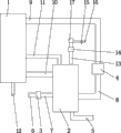
Fig. 1 is a structural representation of the present utility model;
In the accompanying drawing, 1 is the absorption tower, and 2 is the ammonia circulating tank, 3 is gasing pump, and 4 is circulating pump, and 5 is drainage conduit, 6 is air inlet pipe, and 7 is carrier pipe, and 8 is pipeline, 9 is circulating line, and 10 is conveying pipeline, and 11 is the ammonia pipe, 12 is cold water pipe, and 13 is the residual air blast pipe, and 14 is valve, 15 is the gas hybrid chamber, and 16 is the gas supply pipe, and 17 is burner.
The specific embodiment
With reference to Fig. 1, be the treating apparatus of nitriding furnace ammonia of the present utility model.Comprise an ammonia recycle dissolver and a residual air burner.The ammonia recycle dissolver comprises absorption tower 1, ammonia circulating tank 2, gasing pump 3, circulating pump 4.The ammoniacal liquor that the ammonia G﹠W that mixes in inhaling tower obtains is transported in the ammonia circulating tank 2 and stores, and ammonia circulating tank 2 bottoms are connected with the drainage conduit 5 that is used to discharge ammoniacal liquor, discharges from drainage conduit 5 by the ammoniacal liquor that the ammonia recycle dissolver obtains.The ammonia recycle dissolver is provided with the air inlet pipe 6 that connects the nitriding furnace exhaust outlet, and the ammonia circulating tank connects gasing pump 3 by carrier pipe 7, and gasing pump 3 is connected with described air inlet pipe 6.Ammonia circulating tank 2 connects circulating pump 4 by pipeline 8, described absorption tower is connected with circulating pump by circulating line 9, by circulating pump 4 ammoniacal liquor in the ammonia circulating tank 2 is transported in the absorption tower, mix with ammonia repeatedly, ammonia is dissolved in the water better, promptly improves the absorptivity of water ammonia.Absorption tower 1 is connected with ammonia circulating tank 2 by conveying pipeline 10, and the absorption tower is connected with the ammonia circulating tank by ammonia pipe 11.Also be provided with the cold water pipe 12 that in the absorption tower, injects cold water on the absorption tower 1, in time in the absorption tower, replenish moisture content, make ammonia obtain soaking into.The ammonia recycle dissolver is provided with residual air blast pipe 13, and this residual air blast pipe is provided with valve 14, and the residual air blast pipe is connected with described residual air burner.The residual air burner comprises gas hybrid chamber 15, gas supply pipe 16, burner 17 and igniter, and an end of described gas hybrid chamber is connected with the gas supply pipe, and the other end of gas hybrid chamber connects burner by appendix, and igniter is arranged on the burner.
Claims (3)
1. the treating apparatus of a nitriding furnace ammonia, it is characterized in that: comprise an ammonia recycle dissolver and a residual air burner, described ammonia recycle dissolver is provided with the air inlet pipe that connects the nitriding furnace exhaust outlet, and the drainage conduit that is used to discharge ammoniacal liquor, described ammonia recycle dissolver is provided with the residual air blast pipe, this residual air blast pipe is provided with valve, and the residual air blast pipe is connected with described residual air burner.
2. the treating apparatus of nitriding furnace ammonia according to claim 1, it is characterized in that: described ammonia recycle dissolver comprises absorption tower, ammonia circulating tank, gasing pump, circulating pump, the ammonia circulating tank connects gasing pump by carrier pipe, gasing pump is connected with described air inlet pipe, the ammonia circulating tank connects circulating pump by pipeline, described absorption tower is connected with circulating pump by circulating line, the absorption tower is connected with the ammonia circulating tank by conveying pipeline, the absorption tower is connected with the ammonia circulating tank by the ammonia pipe, also is provided with the cold water pipe that injects cold water in the absorption tower on the absorption tower.
3. the treating apparatus of nitriding furnace ammonia according to claim 1, it is characterized in that: the residual air burner comprises gas hybrid chamber, gas supply pipe, burner and igniter, one end of described gas hybrid chamber is connected with the gas supply pipe, the other end of gas hybrid chamber connects burner by appendix, and igniter is arranged on the burner.
Priority Applications (1)
| Application Number | Priority Date | Filing Date | Title |
|---|---|---|---|
| CN2010205979487U CN201848197U (en) | 2010-11-09 | 2010-11-09 | Treatment device for ammonia gas in nitridation furnace |
Applications Claiming Priority (1)
| Application Number | Priority Date | Filing Date | Title |
|---|---|---|---|
| CN2010205979487U CN201848197U (en) | 2010-11-09 | 2010-11-09 | Treatment device for ammonia gas in nitridation furnace |
Publications (1)
| Publication Number | Publication Date |
|---|---|
| CN201848197U true CN201848197U (en) | 2011-06-01 |
Family
ID=44090612
Family Applications (1)
| Application Number | Title | Priority Date | Filing Date |
|---|---|---|---|
| CN2010205979487U Expired - Fee Related CN201848197U (en) | 2010-11-09 | 2010-11-09 | Treatment device for ammonia gas in nitridation furnace |
Country Status (1)
| Country | Link |
|---|---|
| CN (1) | CN201848197U (en) |
-
2010
- 2010-11-09 CN CN2010205979487U patent/CN201848197U/en not_active Expired - Fee Related
Similar Documents
| Publication | Publication Date | Title |
|---|---|---|
| CN102068904B (en) | SCR flue gas denitration technology and device by urea directly-spraying method | |
| CN209854219U (en) | A grate-rotary kiln pellet low NOx emission system | |
| CN109141028B (en) | Chain grate machine-rotary kiln pellet low NOx production device and pellet production method | |
| CN104801171A (en) | SNCR (selective non-catalytic reduction) flue gas denitrification method and device utilizing organic/ammonia nitrogen waste liquid | |
| CN105498563A (en) | Coal mine gas mixing system and mixing method | |
| ITPC20130004A1 (en) | PROCEDURE FOR THE EXTRACTION OF NITROGEN CONTAINED IN DIGESTATES DERIVING FROM METANOGENIC FERMENTATION, ZOOTECHNICAL DEJECTIONS, DEPURATION SLUDGE. | |
| CN201912891U (en) | SCR (selective catalyst reactive) flue gas denitration device adopting direct injection urea method | |
| CN207163232U (en) | The low NOx process units of grate-kiln pelletizing process | |
| CN105879673A (en) | Steel mill coke oven flue gas denitration method and device | |
| CN201971645U (en) | Urea hydrolysis ammonia producing system | |
| CN201848197U (en) | Treatment device for ammonia gas in nitridation furnace | |
| CN105268300B (en) | A kind of joint demercuration method and device based on SNCR | |
| CN203342651U (en) | Urea pyrolysis and SCR (selective catalytic reduction) flue gas denitrification device | |
| CN207680333U (en) | Urea direct-injection SNCR+SCR flue gas denitrification systems | |
| CN1085555C (en) | Equipment and method to exhaust nitridation waste gas and recover residual ammonia | |
| CN221230309U (en) | Front-end dry desulfurization system based on chain-loop production process | |
| CN110201527A (en) | A kind of pre- spray ammonia system and technique of active carbon desulfurization denitration | |
| CN217163872U (en) | Low-temperature denitration treatment device for industrial furnace flue gas | |
| CN203389534U (en) | Selective catalytic reduction (SCR) flue gas denitrification device | |
| CN106731553A (en) | A kind of ammoniacal liquor feeding mechanism and method for flue gas SCR method denitration | |
| CN205412654U (en) | A sintering machine flue gas ammonia method H2O2 oxidation denitrification device | |
| CN207085667U (en) | Denitrification system in biomass Industrial Boiler stove | |
| CN204429102U (en) | A kind of utilization in the urea liquid flue of SCR system directly sprays pyrolysis installation | |
| CN204034549U (en) | A kind of equipment for denitrifying flue gas | |
| CN211328841U (en) | Tunnel furnace denitration system |
Legal Events
| Date | Code | Title | Description |
|---|---|---|---|
| C14 | Grant of patent or utility model | ||
| GR01 | Patent grant | ||
| C17 | Cessation of patent right | ||
| CF01 | Termination of patent right due to non-payment of annual fee |
Granted publication date: 20110601 Termination date: 20111109 |