CN201775843U - Push-type medicine mist generating device for medical treatment and pushing mechanism thereof - Google Patents
Push-type medicine mist generating device for medical treatment and pushing mechanism thereof Download PDFInfo
- Publication number
- CN201775843U CN201775843U CN2010201792541U CN201020179254U CN201775843U CN 201775843 U CN201775843 U CN 201775843U CN 2010201792541 U CN2010201792541 U CN 2010201792541U CN 201020179254 U CN201020179254 U CN 201020179254U CN 201775843 U CN201775843 U CN 201775843U
- Authority
- CN
- China
- Prior art keywords
- generating device
- compressed gas
- medicine mist
- mist generating
- arm
- Prior art date
- Legal status (The legal status is an assumption and is not a legal conclusion. Google has not performed a legal analysis and makes no representation as to the accuracy of the status listed.)
- Expired - Lifetime
Links
Images


Landscapes
- Nozzles (AREA)
Abstract
The utility model discloses a push-type medicine mist generating device for medical treatment and a pushing mechanism thereof. The device comprises a medicine storage container, a spraying structure arranged in the medicine storage container and the pushing mechanism; the pushing mechanism comprises a cylinder seat and a pushing component; the cylinder seat is provided with a gas pipe spliced with the spraying structure and a pressure release hole communicated with the gas pipe; and the pushing component comprises a pulling arm, a valve and an elastic arm abutted against the medicine storage container. The pulling arm is pulled so that the valve closes the pressure release hole and the spraying structure atomizes medicines; when the pulling arm is released, the elastic arm elastically thrusts against the valve to open the pressure release hole so that compressed gas is exhausted and the medicine atomization is stopped. Therefore, the device can be driven to produce or stop producing medicine mist according to the needs of a user, the medicine waste is reduced and the administration efficiency and the medical treatment effect are improved.
Description
Technical field
This utility model relates to a kind of doser, relates in particular to a kind of medical pressing type medicine mist generating device and pressing mechanism thereof.
Background technology
Human diseases are relevant with environment more than 70%, and environment has the greatest impact to the mankind's respiratory system, with the approach of drug delivery patient Yu with the treatment respiratory tract disease, the most effective, generally, and the method that patient's acceptance is the highest is, with the oral drugs oral delivery, but medicine is decomposed at digestive tract easily, so develop per os, nose, the dosing way that lung is sent, it is the spraying Therapeutic Method, making drug mist patients with nebulizer (nebulizer) sucks, the medicine mist directly enters bronchus, diffuses to whole alveolar again, and effect reaches directly than the medicine effective percentage of general oral formula.
Existing nebulizer, comprise a stack shell, be communicated in stack shell bottom a system mist structure, be communicated in a T-shape pipe at stack shell top and be communicated in a sleeve pipe and a separator tube at T-shape pipe two ends respectively, preset medicinal liquid in the tube and by system mist structure with it atomizing, the free end of separator tube is an open space, and patient stings jacket pipe and draws the medicine mist.
When patient inhales, the medicine mist enters respiratory tract via T-shape pipe, sleeve pipe in the stack shell, and sucks outside air to supply patient's inspiration capacity via separator tube.
When patient stops suction, nebulizer still continues to make the medicine mist, and be dissipated to the external world from separator tube dissipation, or when patient exhales, waste gas is disposed to the external world via sleeve pipe, separator tube, in the lump the medicine mist is blown off also, cause waste and contaminated environment, and the actual service efficiency of amount of liquid medicine that presets in the order tube is not good, if will reach the necessary course of treatment, need to increase and preset amount of liquid medicine, thereby improve medical expense.
The utility model content
A purpose of the present utility model is to provide a kind of pressing mechanism of medicine mist generating device, can be according to the conditions of demand of user, and driving device can reduce the medicament waste and promote medication efficient and medical effect to make or to stop the pharmacy mist.
To achieve the above object, this utility model provides a kind of pressing mechanism of medicine mist generating device, described device has a drug reservoir and is installed in a spray structure of described drug reservoir, and described spray structure has a Compressed Gas passage, and this pressing mechanism comprises:
One cylinder base, have peg graft described Compressed Gas passage and voltage supply contract gas communication an appendix, and be communicated with a relief hole of this appendix, form a pivot portion in this cylinder base periphery of this relief hole side; And
One press component comprises and is articulated in that arm is pulled by one of this pivot portion, this pulls that arm extends and to the valve that should the relief hole position sets and be connected in this and pull arm and support an elastic arm that is affixed on described drug reservoir certainly;
Wherein, when pulling this and pulling arm and rotate, this valve will seal this relief hole, and this appendix enters in the described Compressed Gas passage again so that described Compressed Gas is flowed through; Otherwise, discharge the elasticity that is subjected to this elastic arm when this pulls arm and push and make this valve and this relief hole to break away from sealing, this appendix so that described Compressed Gas is flowed through and flowing out from this relief hole.
The pressing mechanism of above-mentioned medicine mist generating device wherein, is pulled the compacting bar that arm forms this elastic arm periphery of compacting in this.
The pressing mechanism of above-mentioned medicine mist generating device, wherein, the aperture center line of this relief hole and the pipeline axial line of this appendix are mutually orthogonal.
Another purpose of the present utility model is to provide a kind of medical pressing type medicine mist generating device, can be according to the conditions of demand of user, and driving device can reduce the medicament waste and promote medication efficient and medical effect to make or to stop the pharmacy mist.
To achieve the above object, this utility model also provides a kind of medical pressing type medicine mist generating device, and this medical pressing type medicine mist generating device comprises:
One drug reservoir has in order to store a chamber of medicament;
One spray structure is installed in this drug reservoir, has a Compressed Gas passage that is communicated with this chamber; And
One pressing mechanism comprises:
One cylinder base, have peg graft this Compressed Gas passage and voltage supply contract gas communication an appendix, and be communicated with a relief hole of this appendix, form a pivot portion in this cylinder base periphery of this relief hole side; And
One press component comprises and is articulated in that arm is pulled by one of this pivot portion, this pulls that arm extends and to the valve that should the relief hole position sets and be connected in this and pull arm and support an elastic arm that is affixed on described drug reservoir certainly;
Wherein, when pulling this and pulling arm and rotate, this valve will seal this relief hole, and this appendix enters in the described Compressed Gas passage again so that described Compressed Gas is flowed through, make spray structure that the described medicament that is stored in this chamber is atomized, otherwise, discharge the elasticity that is subjected to this elastic arm when this pulls arm and push and make this valve and this relief hole to break away from sealing, this appendix so that described Compressed Gas is flowed through and flowing out from this relief hole makes described medicament stop atomizing.
Above-mentioned medical pressing type medicine mist generating device, wherein, this drug reservoir comprises the stack shell with this chamber and is connected in a cover body of this stack shell one end.
Above-mentioned medical pressing type medicine mist generating device, wherein, this cover body comprises a lower cover, and this lower cover has an inlet channel independent of each other and an exhaust passage.
Above-mentioned medical pressing type medicine mist generating device, wherein, this stack shell offers a mixed gas outlet that is communicated with this chamber, and this inlet channel is to should chamber configuration, and this exhaust passage is to should the mixed gas outlet configuration.
Above-mentioned medical pressing type medicine mist generating device wherein, is formed with a mixed-gas channel that is communicated with this chamber and this mixed gas outlet between this lower cover and this stack shell.
Above-mentioned medical pressing type medicine mist generating device, wherein, this lower cover offers the air inlet that is communicated with this inlet channel, and is communicated with a steam vent of this exhaust passage, and this lower cover comprise corresponding air inlet do to open and close and stride a breather cheek valve of being located at inlet channel, and corresponding steam vent make to open and close and stride an one-way exhaust valve of being located at the exhaust passage.
Above-mentioned medical pressing type medicine mist generating device, wherein, this drug reservoir also comprises in order to this steam vent of filter envelope a filter material that should steam vent be provided with, and this cover body also comprises should the steam vent configuration and be connected in a loam cake of this lower cover, and this filter material is installed in this loam cake.
Above-mentioned medical pressing type medicine mist generating device, wherein, this spray structure comprises an awl post that takes shape in this stack shell, and this Compressed Gas tunnel-shaped is formed in the recess side of this awl post, and this awl post offers the Compressed Gas inlet that is communicated with this chamber and this Compressed Gas passage.
Above-mentioned medical pressing type medicine mist generating device, wherein, the aperture size of this relief hole is greater than the aperture size of this Compressed Gas inlet.
Above-mentioned medical pressing type medicine mist generating device, wherein, this spray structure also comprises a cone-shaped hood that is arranged at around this awl post, is formed with a fluid passage between this cone-shaped hood and this awl post.
Above-mentioned medical pressing type medicine mist generating device, wherein, this spray structure also comprise to should Compressed Gas the block that is provided with of inlet and this fluid passage.
Above-mentioned medical pressing type medicine mist generating device wherein, is pulled the compacting bar that arm forms this elastic arm periphery of compacting in this.
Above-mentioned medical pressing type medicine mist generating device, wherein, the aperture center line of this relief hole and the pipeline axial line of this appendix are mutually orthogonal.
Compared to prior art, the utlity model has following effect:
Can make or stop the pharmacy mist according to the conditions of demand of user, only need continue to pull pressing mechanism and can in drug reservoir, produce the medicine mist, drawing the medicine mist for sufferer treats, when sufferer need not be drawn the medicine mist, only need discharge pressing mechanism and can make spray structure stop to produce the medicine mist, so then can reduce the medicament waste and promote medication efficient and medical effect.
Below in conjunction with the drawings and specific embodiments this utility model is described in detail, but not as to qualification of the present utility model.
Description of drawings
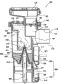
Fig. 1 three-dimensional exploded view of the present utility model;
Fig. 2 three-dimensional combination figure of the present utility model;
Fig. 3 combination section of the present utility model;
Fig. 4 manufacturing medicine of the present utility model mist figure;
Fig. 5 absorption medicine of the present utility model mist figure;
Fig. 6 expiration discharging of the present utility model figure;
Fig. 7 pharmacy mist figure that stops of the present utility model.
Wherein, Reference numeral
Mixed gas outlet 112
Protruding pipe 113
Inlet channel 123
Steam vent 126
One-way exhaust valve 128
Mixed-gas channel 129
Cone-shaped hood 220
Pull arm 321
Compacting bar 324
The specific embodiment
Relevant detailed description of the present utility model and technology contents will cooperate graphic being described as follows, yet appended graphic only purposes as an illustration is not to be used to limit to this utility model.
This utility model relates to a kind of pressing mechanism, and medical pressing type medicine mist generating device of medicine mist generating device, please refer to Fig. 1 to shown in Figure 3, and device comprises a drug reservoir 100, a spray structure 200, reaches a pressing mechanism 300.
Stack shell 110 is cylindric, but does not exceed with this shape, and its size, shaped design grip to preferable with the hand that is fit to human body, and stack shell 110 inside have a chamber 111, and chamber 111 also connects the top of stack shell 110.
The periphery wall top of stack shell 110 offers a mixed gas outlet 112, and mixed gas outlet 112 also is communicated with chamber 111, and mixed gas outlet 112 periphery radial protrusions form a protruding pipe 113 again, and protruding pipe 113 is hollow form and is communicated with mixed gas outlet 112.
Again, lower cover 121 comprise corresponding air inlet 125 do to open and close and stride a breather cheek valve 127 of being located at inlet channel 123, and corresponding steam vent 126 make to open and close and stride an one-way exhaust valve 128 of being located at exhaust passage 124, in addition, be formed with a mixed-gas channel 129 between stack shell 110 inwalls of lower cover 121 and mixed gas outlet 112 sides, mixed-gas channel 129 is communicated with chamber 111 and mixed gas outlet 112.
Corresponding steam vents 126 configurations of loam cake 122 and be connected in the end face of lower cover 121,130 of filter materials are installed in loam cake 122, filter material 130 is in order to filter envelope steam vent 126, loam cake 122 and filter material 130 are the object of additivity function, it is done bacteriological filtration at patient expired gas and uses, and can install additional in response to user demand.
To chamber 111 punch formings, form in the recess side of awl post 210 has a Compressed Gas passage 211 to awl post 210 by the interior diapire of stack shell 110, and the top of awl post 210 offers the Compressed Gas inlet 212 that is communicated with chamber 111 and Compressed Gas passage 211.
Cone-shaped hood 220 is penetration state, and cone-shaped hood 220 is arranged at the convex side outside of awl post 210, and cone-shaped hood 220 is formed with a fluid passage 221 with boring space slight distance between the post 210 again.
The passway of corresponding Compressed Gas inlet 212 of block 230 and fluid passage 221 and be arranged at cone-shaped hood 220 and awl post 210 tops.
Pull arm 321 and be articulated in pivot portion 313, arm 321 extends valve 322 and corresponding relief hole 312 positions set and can open and close by corresponding relief hole 312 from pulling, elastic arm 323 is connected in to pull arm 321 and support and is affixed on stack shell 110, pull arm 321, valve 322, and elastic arm 323 can be formed in one, to simplify fabrication schedule and to reduce manufacturing cost and promote structural strength, elastic arm 323 can also with pull arm 321 and be connected for combination type, reach broader flexible application category, pull arm 321 again and form a compacting bar 324, compacting bar 324 is in order to the periphery wall of compacting elastic arm 323.
Use this utility model to make the medicine mist so that the method for suction to be provided, please refer to Fig. 4 to shown in Figure 7, at first a medicament 400 is filled and store in chamber 111, medicament 400 is used for the treatment of the disease of human body, the liquid level of medicament 400 is no more than Compressed Gas inlet 212, and in the medicament 400 meeting incoming fluid passages 221.
Pour into a Compressed Gas 500 from appendix 311, in general Compressed Gas 500 is a compressed oxygen, Compressed Gas 500 reaches 211 circulations of Compressed Gas passage in appendix 311, when sufferer need be inhaled medicine, pull arm 321 this moment, pull arm 321 and rotate and drive valve 322 sealing relief holes 312, and, make its deflection deformation and the storage elasticity restoring force simultaneously with compacting bar 324 compacting elastic arms 323 peripheries by pivot portion 313.
When the close relief hole 312 of valve 322 envelopes, Compressed Gas 500 unique flow paths only enter in the Compressed Gas passage 211 for the appendix 311 of flowing through again, Compressed Gas 500 then enters littler Compressed Gas inlet 212 from Compressed Gas passage 211, venturi-effect can take place, and promptly Compressed Gas 500 is with medicament 400 sucking-off from fluid passage 221.
Compressed Gas 500 attracts medicaments 400 and impacts medicament 400 and make its refinement, medicament 400 after the refinement is compressed gas 500 and sprays to and clash into block 230, making its splash atomizing and mixing with Compressed Gas 500 is that a medicine mist 600 is sent forth towards periphery, and medicine mist 600 major parts can be filled in the inlet channel 123.
Sufferer is stung with oral area and is clamped protruding pipe 113, and air-breathing medicine mist 600 in the inlet channel 123 is sucked pulmonarys via chamber 111, mixed-gas channel 129, mixed gas outlet 112, and the inspiratory force of sufferer can make breather cheek valve 127 open air inlet 125, and makes one-way exhaust valve 128 deadend steam vents 126.
At this moment, outside air then can enter air inlet 125, supplying the inspiration capacity of sufferer, and most medicine mist 600 can be directed at mixed gas outlet 112 simultaneously whereby to allow sufferer draw, and can not be drawn onto too much air, can increase medicament 400 absorption efficiencies and reduce the treatment time-histories.
After inhaling medicine, sufferer will inevitably exhale again so that the waste gas in the pulmonary is discharged, the expiration power of sufferer can make one-way exhaust valve 128 open steam vent 126, the waste gas that sufferer is breathed out drains into the external world via mixed gas outlet 112 and exhaust passage 124, and filtered by filter material 130 simultaneously, diffuse to the external world and influence hygienic conditions to avoid virus or antibacterial in the waste gas.
This moment is because the inspiratory force disappearance, make breather cheek valve 127 closed grate hole 126 again, make medicine mist 600 can not run off, reduce unnecessary waste, and because of the channel cross-sectional area of mixed-gas channel 129 much smaller than the exhaust passage 124 channel cross-sectional area, make waste gas be difficult to enter in the chamber 111 and the overwhelming majority 124 drains into the external world from the exhaust passage.
When sufferer is desired to stop to draw medicine mist 600, only need discharge and pull arm 321, the elastic arm 323 of then deflection deformation breaks away from sealing with valve 322 and relief hole 312 whereby with its elastic restoring force reinstatement and elasticity pushing and pressing compacting bar 324, makes relief hole 312 open-minded.
When relief hole 312 is opened, because the aperture size of relief hole 312 is much larger than the aperture size of Compressed Gas inlet 212, then Compressed Gas 500 can flow toward hindering little position, therefore cause Compressed Gas 500 to flow out to the external world and can not enter Compressed Gas inlet 212, stop to produce medicine mist 600 in this way from relief hole 312 dissipations.
The utlity model has suitable ease of use, sufferer only need continue to pull pressing mechanism 300 can draw medicine mist 600, discharge pressing mechanism 300 and just do not have 600 generations of medicine mist, so can reduce medicament 400,600 wastes of medicine mist, with these a large amount of medication efficient, medical effects of promoting, again in therapeutic process, sufferer is blown and but medicine mist 600 can not discharged from chamber 111, can effectively preserve medicament 400, medicine mist 600, in addition, the waste gas that sufferer blows out can be filtered by filter material 130, avoids virus or antibacterial in the waste gas to diffuse to the external world, and can safeguard the environment of health.
Certainly; this utility model also can have other various embodiments; under the situation that does not deviate from this utility model spirit and essence thereof; those of ordinary skill in the art work as can make various corresponding changes and distortion according to this utility model, but these corresponding changes and distortion all should belong to the protection domain of the appended claim of this utility model.
Claims (16)
1. the pressing mechanism of a medicine mist generating device, described device has a drug reservoir and is installed in a spray structure of described drug reservoir, and described spray structure has a Compressed Gas passage, it is characterized in that, and this pressing mechanism comprises:
One cylinder base, have peg graft described Compressed Gas passage and voltage supply contract gas communication an appendix, and be communicated with a relief hole of this appendix, form a pivot portion in this cylinder base periphery of this relief hole side; And
One press component comprises and is articulated in that arm is pulled by one of this pivot portion, this pulls that arm extends and to the valve that should the relief hole position sets and be connected in this and pull arm and support an elastic arm that is affixed on described drug reservoir certainly;
Wherein, this is pulled arm and turns to this valve and seal this relief hole position, and Compressed Gas this appendix of flowing through enters in the described Compressed Gas passage again; Otherwise, discharging the elasticity that is subjected to this elastic arm when this pulls arm and push and make this valve and this relief hole disengaging sealing, described Compressed Gas is flowed through this appendix and is flowed out from this relief hole.
2. the pressing mechanism of medicine mist generating device according to claim 1 is characterized in that, pulls the compacting bar that arm forms this elastic arm periphery of compacting in this.
3. the pressing mechanism of medicine mist generating device according to claim 1 is characterized in that, the aperture center line of this relief hole and the pipeline axial line of this appendix are mutually orthogonal.
4. a medical pressing type medicine mist generating device is characterized in that, comprising:
One drug reservoir has in order to store a chamber of medicament;
One spray structure is installed in this drug reservoir, has a Compressed Gas passage that is communicated with this chamber; And
One pressing mechanism comprises:
One cylinder base, have peg graft this Compressed Gas passage and voltage supply contract gas communication an appendix, and be communicated with a relief hole of this appendix, form a pivot portion in the cylinder base periphery of this relief hole side; And
One press component comprises and is articulated in that arm is pulled by one of this pivot portion, this pulls that arm extends and to the valve that should the relief hole position sets and be connected in this and pull arm and support an elastic arm that is affixed on described drug reservoir certainly;
Wherein, this is pulled arm and turns to this valve and seal this relief hole, and Compressed Gas this appendix of flowing through enters in the described Compressed Gas passage again, makes spray structure that the described medicament that is stored in this chamber is atomized; Otherwise, discharging the elasticity that is subjected to this elastic arm when this pulls arm and push and make this valve and this relief hole to break away from sealing, described Compressed Gas is flowed through this appendix and is flowed out from this relief hole, makes described medicament stop to atomize.
5. medical pressing type medicine mist generating device according to claim 4 is characterized in that, this drug reservoir comprises the stack shell with this chamber and is connected in a cover body of this stack shell one end.
6. medical pressing type medicine mist generating device according to claim 5 is characterized in that this cover body comprises a lower cover, and this lower cover has an inlet channel independent of each other and an exhaust passage.
7. medical pressing type medicine mist generating device according to claim 6 is characterized in that, this stack shell offers a mixed gas outlet that is communicated with this chamber, and this inlet channel is to should chamber configuration, and this exhaust passage is to should the mixed gas outlet configuration.
8. medical pressing type medicine mist generating device according to claim 7 is characterized in that, is formed with a mixed-gas channel that is communicated with this chamber and this mixed gas outlet between this lower cover and this stack shell.
9. medical pressing type medicine mist generating device according to claim 6, it is characterized in that, this lower cover offers the air inlet that is communicated with this inlet channel, and is communicated with a steam vent of this exhaust passage, and this lower cover comprise corresponding air inlet do to open and close and stride a breather cheek valve of being located at inlet channel, and corresponding steam vent make to open and close and stride an one-way exhaust valve of being located at the exhaust passage.
10. medical pressing type medicine mist generating device according to claim 9, it is characterized in that, this drug reservoir also comprises in order to this steam vent of filter envelope the filter material to should steam vent being provided with, this cover body also comprise to should steam vent configuration and be connected in a loam cake of this lower cover, this filter material is installed in this loam cake.
11. medical pressing type medicine mist generating device according to claim 5, it is characterized in that, this spray structure comprises an awl post that takes shape in this stack shell, this Compressed Gas tunnel-shaped is formed in the recess side of this awl post, and this awl post offers the Compressed Gas inlet that is communicated with this chamber and this Compressed Gas passage.
12. medical pressing type medicine mist generating device according to claim 11 is characterized in that, the aperture size of this relief hole is greater than the aperture size of this Compressed Gas inlet.
13. medical pressing type medicine mist generating device according to claim 11 is characterized in that, this spray structure also comprises a cone-shaped hood that is arranged at around this awl post, is formed with a fluid passage between this cone-shaped hood and this awl post.
14. medical pressing type medicine mist generating device according to claim 13 is characterized in that, this spray structure also comprise to should Compressed Gas the block that is provided with of inlet and this fluid passage.
15. medical pressing type medicine mist generating device according to claim 4 is characterized in that, pulls the compacting bar that arm forms this elastic arm periphery of compacting in this.
16. medical pressing type medicine mist generating device according to claim 4 is characterized in that the aperture center line of this relief hole and the pipeline axial line of this appendix are mutually orthogonal.
Priority Applications (1)
| Application Number | Priority Date | Filing Date | Title |
|---|---|---|---|
| CN2010201792541U CN201775843U (en) | 2010-04-27 | 2010-04-27 | Push-type medicine mist generating device for medical treatment and pushing mechanism thereof |
Applications Claiming Priority (1)
| Application Number | Priority Date | Filing Date | Title |
|---|---|---|---|
| CN2010201792541U CN201775843U (en) | 2010-04-27 | 2010-04-27 | Push-type medicine mist generating device for medical treatment and pushing mechanism thereof |
Publications (1)
| Publication Number | Publication Date |
|---|---|
| CN201775843U true CN201775843U (en) | 2011-03-30 |
Family
ID=43789080
Family Applications (1)
| Application Number | Title | Priority Date | Filing Date |
|---|---|---|---|
| CN2010201792541U Expired - Lifetime CN201775843U (en) | 2010-04-27 | 2010-04-27 | Push-type medicine mist generating device for medical treatment and pushing mechanism thereof |
Country Status (1)
| Country | Link |
|---|---|
| CN (1) | CN201775843U (en) |
Cited By (1)
| Publication number | Priority date | Publication date | Assignee | Title |
|---|---|---|---|---|
| CN107899112A (en) * | 2017-12-06 | 2018-04-13 | 何爱建 | It is a kind of based on the Respiratory Medicine of medical field preventing phlegm from forming and stopping coughing atomizer |
-
2010
- 2010-04-27 CN CN2010201792541U patent/CN201775843U/en not_active Expired - Lifetime
Cited By (1)
| Publication number | Priority date | Publication date | Assignee | Title |
|---|---|---|---|---|
| CN107899112A (en) * | 2017-12-06 | 2018-04-13 | 何爱建 | It is a kind of based on the Respiratory Medicine of medical field preventing phlegm from forming and stopping coughing atomizer |
Similar Documents
| Publication | Publication Date | Title |
|---|---|---|
| US20110253134A1 (en) | Press-type medical aerosol generating device and pressing mechanism for the same | |
| JP5368661B1 (en) | Gas mist inhaler | |
| US20120174917A1 (en) | Press-type medical nebulizer and pressing means thereof | |
| CN201012211Y (en) | Medicament atomizing inhalation apparatus | |
| CN106730188A (en) | A kind of Respiratory Medicine is atomized chemical spraying device | |
| CN201969147U (en) | Pressing type medicine mist generating device for medical treatment and pressing mechanism thereof | |
| CN111214735A (en) | Atomizer mist storage tank | |
| CN202314778U (en) | Atomizing inhalation device for paediatric internal medicine | |
| CN110604855A (en) | Dedicated atomizing equipment of paediatrics respiratory therapy | |
| CN206715012U (en) | A kind of vaporizer | |
| CN202198932U (en) | Simple medicine atomizer | |
| CN104208778B (en) | Nebulization drug delivery system for respiratory circuit | |
| CN201596202U (en) | Medical aerosol inhalator | |
| CN208525585U (en) | A kind of atomization face cup | |
| CN201775843U (en) | Push-type medicine mist generating device for medical treatment and pushing mechanism thereof | |
| CN202154918U (en) | Suction pipe of medical atomizer | |
| CN208405633U (en) | A kind of medical mouth nasal aerosol delivery device | |
| EP2388035B1 (en) | Press-type medical aerosol generating device and pressing mechanism for the same | |
| CN105126213B (en) | Portable first-aid inhalation system | |
| CN204521853U (en) | A kind of autogenous cutting formula nebulizer | |
| CN210078497U (en) | Breathing circuit capable of carrying out atomization administration | |
| CN204106767U (en) | For the atomized medicine introducing system of breathing circuit | |
| CN103055387A (en) | Atomization device synchronous with respiration time | |
| CN201329112Y (en) | Multifunctional oral/nasal tube | |
| CN2627861Y (en) | Oxygen taking and toxin removing mask according to requirement |
Legal Events
| Date | Code | Title | Description |
|---|---|---|---|
| C14 | Grant of patent or utility model | ||
| GR01 | Patent grant | ||
| CX01 | Expiry of patent term | ||
| CX01 | Expiry of patent term |
Granted publication date: 20110330 |