CN201730962U - Five-degree-of-freedom permanent magnet biased magnetic bearing - Google Patents
Five-degree-of-freedom permanent magnet biased magnetic bearing Download PDFInfo
- Publication number
- CN201730962U CN201730962U CN2010201741183U CN201020174118U CN201730962U CN 201730962 U CN201730962 U CN 201730962U CN 2010201741183 U CN2010201741183 U CN 2010201741183U CN 201020174118 U CN201020174118 U CN 201020174118U CN 201730962 U CN201730962 U CN 201730962U
- Authority
- CN
- China
- Prior art keywords
- stator
- axial
- magnetic
- permanent magnet
- magnetic pole
- Prior art date
- Legal status (The legal status is an assumption and is not a legal conclusion. Google has not performed a legal analysis and makes no representation as to the accuracy of the status listed.)
- Expired - Lifetime
Links
Images

Classifications
-
- F—MECHANICAL ENGINEERING; LIGHTING; HEATING; WEAPONS; BLASTING
- F16—ENGINEERING ELEMENTS AND UNITS; GENERAL MEASURES FOR PRODUCING AND MAINTAINING EFFECTIVE FUNCTIONING OF MACHINES OR INSTALLATIONS; THERMAL INSULATION IN GENERAL
- F16C—SHAFTS; FLEXIBLE SHAFTS; ELEMENTS OR CRANKSHAFT MECHANISMS; ROTARY BODIES OTHER THAN GEARING ELEMENTS; BEARINGS
- F16C32/00—Bearings not otherwise provided for
- F16C32/04—Bearings not otherwise provided for using magnetic or electric supporting means
- F16C32/0406—Magnetic bearings
- F16C32/044—Active magnetic bearings
- F16C32/0459—Details of the magnetic circuit
- F16C32/0461—Details of the magnetic circuit of stationary parts of the magnetic circuit
- F16C32/0465—Details of the magnetic circuit of stationary parts of the magnetic circuit with permanent magnets provided in the magnetic circuit of the electromagnets
-
- F—MECHANICAL ENGINEERING; LIGHTING; HEATING; WEAPONS; BLASTING
- F16—ENGINEERING ELEMENTS AND UNITS; GENERAL MEASURES FOR PRODUCING AND MAINTAINING EFFECTIVE FUNCTIONING OF MACHINES OR INSTALLATIONS; THERMAL INSULATION IN GENERAL
- F16C—SHAFTS; FLEXIBLE SHAFTS; ELEMENTS OR CRANKSHAFT MECHANISMS; ROTARY BODIES OTHER THAN GEARING ELEMENTS; BEARINGS
- F16C32/00—Bearings not otherwise provided for
- F16C32/04—Bearings not otherwise provided for using magnetic or electric supporting means
- F16C32/0406—Magnetic bearings
- F16C32/044—Active magnetic bearings
- F16C32/0474—Active magnetic bearings for rotary movement
- F16C32/0489—Active magnetic bearings for rotary movement with active support of five degrees of freedom, e.g. two radial magnetic bearings combined with an axial bearing
Abstract
The utility model provides a five-degree-of-freedom permanent magnet biased magnetic bearing, which comprises a stator component and a rotor component. Radial stator magnetic poles and axial stator magnetic poles on the stator component are respectively arranged in one-to-one correspondence to magnetic poles on the rotor component; the stator component positioned on the outer side of the rotor component includes a radial stator, an axial stator and a radial stator which are sequentially arranged along the axial direction of the stator component; and the rotor component includes a rotor shaft and rotor wrought iron sleeved on the rotor shaft. The five-degree-of-freedom permanent magnet biased magnetic bearing simplifies the structure of the rotor, is convenient in assembly, and is low in power consumption as grooves are arranged on the radial stator magnetic poles.
Description
Technical field
The utility model relates to a kind of 5-freedom permanent magnetism off-set magnetic axis, particularly a kind of 5-freedom permanent magnetism off-set magnetic axis that is applicable to the no bearing supporting of rotary component in the machinery such as bearing-free motor and high speed flywheel energy-storage system.
Background technique
Magnetic bearing claims magnetic suspension bearing again, be to utilize magnetic force that rotor is suspended in the air, make between rotor and the stator and do not have Mechanical Contact, promptly between rotor and stator, form the air clearance (abbreviation air gap) of certain distance, so the rotor of magnetic suspension bearing can reach very high rotating speed, and do not have mechanical wear, need not to lubricate, energy consumption is low, advantage such as pollution-free, be specially adapted at a high speed, vacuum and super clean application.
At present, the mode that magnetic bearing provides according to magnetic force can be divided into following several: first kind is Active Magnetic Suspending Bearing, there is bias current in this magnetic bearing coil, so that bias magnetic field to be provided, superpose by the control electric current control magnetic flux that the control winding produces of flowing through, thereby produce controlled magnetic buoyancy, volume, weight and power consumption are all bigger.Second kind is passive magnetic bearing, the suspending power of this magnetic bearing is provided by permanent magnetism fully, and its required controller is simple, and the suspension power consumption is little, but rigidity and damping are all smaller, generally apply to only support object or alleviate the load that acts on the traditional bearing in a direction.The third is a hybrid magnetic bearing, the electromagnet that this magnetic bearing adopts permanent-magnet material to substitute in the active magnetic bearings produces bias magnetic field, the just balanced load that electromagnet provides or the controlling magnetic field of interference, greatly reduce the power loss that produces because of bias current, the required Number of ampere turns of electromagnet is half of active magnetic bearings, dwindle the volume of eating bearing, alleviated its weight, and improved bearing capacity.
The research to five degree-of-freedom permanent magnet biased magnetic bearing at present mainly contains following several: a kind of is to adopt the combination of independent axial magnetic bearing and radial direction magnetic bearing to realize the supporting of five degree of freedom, and this mode makes that whole axial dimension is longer.Another kind is that radial and axial magnetic bearing is integrated, but the rotor structure complexity, rotary inertia is big, and the stator radial dimension is also bigger, the assembling difficulty; Axially control does not have by dynamic stiffness, and consumed power is big; Some radially the magnetic circuit of ACTIVE CONTROL can not form the closed-loop path, so consumed power is bigger.
The model utility content
The purpose of this utility model is to solve above-mentioned technical problem, and a kind of 5-freedom permanent magnetism off-set magnetic axis that is applicable to the no bearing supporting of rotary component in the machinery such as bearing-free motor and high speed flywheel energy-storage system is provided.
The purpose of this utility model is achieved through the following technical solutions: a kind of five degree-of-freedom permanent magnet biased magnetic bearing, comprise stator module and rotor assembly, it is characterized in that: radial stator magnetic pole on the stator module and axial stator magnetic pole respectively with rotor assembly on magnetic pole be provided with one to one.
Further, described stator module is positioned at the outside of rotor assembly, comprise, along the radial stator that the stator module axial direction is arranged successively, an axial stator, a radial stator, each radial stator radially extends four radial stator magnetic poles to the rotor assembly direction, relative a pair of radial stator magnetic pole bias magnetic field direction is opposite, and a control coil radially is installed on each radial stator magnetic pole, and the radially control coil on relative a pair of radial stator magnetic pole is in series.
Further, all have one or more grooves on each radial stator magnetic pole.
Further, axial stator on the rotor assembly axial direction between two radial stators, the two ends of its axial direction connect a permanent magnet separately, two permanent magnets are opposite at axial magnetizing direction.
Further, two two ends of being located at axial stator that radial stator is symmetrical respectively, the outer surface of its internal surface and permanent magnet sticks together.
Further, axial stator has two spaced apart axial stator magnetic poles on the stator module axial direction, forms a groove between two axial stator magnetic poles, is provided with axial control coil in the groove.
Further, described rotor assembly comprises a rotor shaft and the rotor soft iron that is sleeved on the rotor shaft.
Further, described rotor soft iron is at four magnetic poles of axial distribution, and is corresponding with the magnetic pole on the stator module respectively.
Further, all have one or more grooves on each radial stator magnetic pole, have the groove of equal number on the described rotor soft iron with on the corresponding magnetic pole of radial stator magnetic pole.
Further, on the rotor soft iron with the 2/3 magnetic pole thickness setting of on the stator module axial direction, staggering of the corresponding magnetic pole of axial stator magnetic pole.
The beneficial effects of the utility model are mainly reflected in: simplified rotor structure, and easy to assembly, on the radial stator magnetic pole, to slot, consumed power is low.
Description of drawings
Below in conjunction with accompanying drawing technical solutions of the utility model are described further:
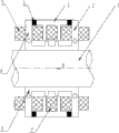
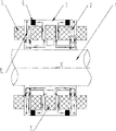
Fig. 1: the structural representation of preferred implementation of the present utility model.
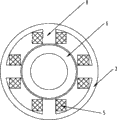
Fig. 2: the left view of the structural representation of Fig. 1 of preferred implementation of the present utility model.
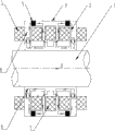
Fig. 3: the bias magnetic field schematic diagram of preferred implementation of the present utility model
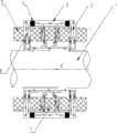
Fig. 4: the floating control of the radially magnetic of preferred implementation of the present utility model magnetic circuit schematic diagram.
Fig. 5: the floating control of the axial magnetic of preferred implementation of the present utility model magnetic circuit schematic diagram.
Fig. 6: the floating control of the twisted magnetic of preferred implementation of the present utility model magnetic circuit schematic diagram.
Wherein:
1 rotor shaft 5 is control coil radially
2 radial stators, 6 rotor soft irons
3 axial stator, 7 axial control coils
4 permanent magnets, 8 radial stator magnetic poles
Embodiment
About addressing other technologies content, characteristics and effect before the utility model, in the following detailed description that cooperates with reference to one of graphic preferred embodiment, can clearly present.
Fig. 1 is the five degree-of-freedom permanent magnet biased magnetic bearing schematic representation of a kind of embodiment of the present utility model, and Fig. 2 is the left view of Fig. 1, in conjunction with Fig. 1 and Fig. 2.This five degree-of-freedom permanent magnet biased magnetic bearing mainly is made up of stator module and rotor assembly, and rotor assembly comprises rotor shaft 1, and the axial axis of rotor is an X-axis, and this axis is axial axis, the rotor soft iron 6 of rotor assembly simultaneously; Stator module comprise the annular permanent magnet 4 of two radial stators 2, axial stator 3, two axial chargings and radially control coil 5 and axially control coil 7 form.Radial stator 2, axial stator 3 and rotor soft iron are processed by the soft magnetic material of higher magnetic property; Annular permanent magnet 4 is processed by the NdFeB material of high saturated magnetic induction.
Concrete, the outside of rotor shaft 1 arranges that along X-axis direction 3, one radial stators 2 of 2, one axial stator of a radial stator are arranged successively.Radial stator 2 is an annular, radially extend four radial stator magnetic poles 8 to rotor shaft 1 direction in its ring, four radial stator magnetic poles 8 lay respectively on the fourth class branch on the circumference of radial stator 2, be positioned at the unified axial position on the X-axis direction simultaneously, relative a pair of radial stator magnetic pole 8 magnetic directions are opposite.Radially control coil 5 is installed in respectively on four radial stator magnetic poles 8 of radial stator 2, and the radially control coil 5 on relative a pair of radial stator magnetic pole 8 is in series.All have one or more grooves on each radial stator magnetic pole 8, two radial stators 2 have eight radial stator magnetic poles 8, and each radial stator magnetic pole 8 is provided with a radially control coil 5, promptly are provided with eight radially control coils 5 altogether.
Rotor soft iron 6 is sleeved on the rotor shaft 1, the corresponding rotor magnetic pole that is provided with of each magnetic pole of last and the axial stator 3 and the radial stator 2 of rotor soft iron 6.Identical with the X-axis axial position of the X-axis axial position of radial stator magnetic pole 8 corresponding rotor magnetic poles under steady state and electronics magnetic pole 8 radially, diameter is identical, and has on this rotor magnetic pole and radially electronics magnetic pole 8 positions and the corresponding groove of shape.Identical with the diameter shaft of the corresponding rotor magnetic pole of axial stator magnetic pole to the diameter of magnetic pole of the stator, the axis of symmetry direction skew between two axial stator magnetic poles of 2/3rds magnetic pole thickness yet its X-axis axial position has staggered each other, the X-axis axial position of this rotor magnetic pole.The axial force maximum that under identical Number of ampere turns situation, produces like this.
The bias magnetic field schematic diagram that Fig. 3 produces for permanent magnet.The magnetic line of force shown in the figure is produced by permanent magnet 4, is mainly used to set up quiescent biasing magnetic field.
With reference to Fig. 3 and Fig. 4, rotor shaft 1 is when the radial equilibrium position, because the symmetry properties of structure, the induction level that annular permanent magnet 4 produces in radial air gap is identical, and the suction up and down that this moment, rotor shaft 1 was subjected to equates.If this moment, rotor shaft 1 was subjected to downward perturbed force, rotor shaft 1 will depart from the equilibrium position, and a little displacement is arranged downwards, and the magnetic induction intensity that will produce in the radial air gap about will causing like this changes, and promptly following air gap reduces, and magnetic induction intensity increases; Top air gap increases, and magnetic induction intensity reduces.Because square being directly proportional of magnetic force and magnetic induction intensity when the magnetic pole area is certain, therefore the suction below is greater than top suction, add control electric current before, rotor can't be got back to the equilibrium position.At this moment, the radial displacement transducer (figure does not show) that is located at two ends, the rotor left and right sides will detect the displacement amount of rotor shaft 1 skew reference position, a controller is converted into control signal with this displacement signal, be converted into through a power amplifier then and control in the coil that is in series on each radial stator magnetic pole 8 about the electric current feeding, thus generation controlling magnetic field as shown in Figure 4.Be that stack strengthens in the superincumbent radial air gap of magnetic induction intensity that electromagnetic field produces, stack weakens in the air gap below, the magnetic force that produce in the air gap this moment in the above will be greater than the magnetic force in the following air gap, the magnetic force of air gap is greater than the magnetic force of following air gap above producing, be that rotor shaft 1 will be subjected to a bonding force that makes progress, make rotor shaft 1 can be pulled back to the place, equilibrium position.
With reference to Fig. 3 and Fig. 5, in the axial direction, rigidity is mainly provided by the magnetic field that permanent magnet 4 produces, and electromagnetic field is mainly used to adjust axial position, and power consumption is less.On radial stator magnetic pole 8, open one or more grooves, utilize the principle of magnetic potential minimum, can improve axial so greatly by dynamic stiffness.When rotor shaft 1 during in the longitudinal balance position, because the symmetry properties of structure, rotor shaft 1 is not axially stressing.When rotor shaft 1 is subjected to left perturbed force, since axially have bigger by dynamic stiffness, the position offset of the generation of rotor shaft 1 will be very little, the permanent magnetism power of the axial stator magnetic pole on axial stator left side generation at this moment will have the trend that rotor is withdrawn into the equilibrium position less than right axis to the permanent magnetism power that magnetic pole of the stator produces.Detected displacement signal will be by controller for axial sensor (figure does not show), and power amplifier is converted to the control electric current and feeds axial control coil, axially controls electromagnetic field as shown in Figure 5 and produce.In the magnetic pole air gap on the right, electromagnetic field will strengthen with the permanent magnetic field stack; In the magnetic pole air gap of on the left side, electromagnetic field will weaken with the permanent magnetic field stack, so more increased the rotor axial restoring force, and the power that consumes be less.
With reference to Fig. 3 and Fig. 6, when rotor shaft 1 during in the equilibrium position, rotor shaft 1 is not to be subjected to moment of torsion.Suppose to be subjected to an interference when rotor, produced the deflection (reversing) of winding perpendicular to the axis of X-axis along the clockwise direction among the figure, radial stator magnetic pole 8 and axial stator magnetic pole will produce a dislocation with corresponding rotor magnetic pole this moment, principle according to the magnetic potential minimum, to produce a counterclockwise restoring moment this moment, generation makes rotor be returned to the trend of equilibrium position, in the corresponding coil in two ends, the left and right sides, feed opposite control electric current (the electromagnetism magnetic line of force of generation as shown in phantom in Figure 6) on this basis respectively, can easier rotor shaft 1 be withdrawn into the equilibrium position.It below promptly is the principle of suspension of five-freedom degree magnetic control.
Five degree-of-freedom permanent magnet biased magnetic bearing of the present utility model, utilized the annular permanent magnet of two axial chargings that quiescent biasing magnetic field is provided, and provide axial by dynamic stiffness with wind passive torsional stiffness perpendicular to the axial axis of stator module, effectively reduced the consumption of power.Whole apparatus structure is simple, compact, and is easy for installation.Rotor of the present utility model has the same external diameter, and then realizes axial magnetic suspension control, has simplified the structure of rotor, the aspect assembling of bearing.Axial stator magnetic pole of the present utility model and corresponding rotor magnetic pole certain distance that staggers, this distance is 2/3rds of a magnetic pole thickness, the axial force maximum that produces under same Number of ampere turns situation.The utility model is slotted on the radial stator magnetic pole, utilize the principle of magnetic potential minimum and make axially and torsional direction produce bigger by dynamic stiffness, thereby make axial and torsional direction more easy to control, the power of consumption is lower.We's bright employing permeability high soft magnetic material can reduce the overall structure size of bearing greatly, can use on micromachine.The utility model has been realized the magnetic suspension of five degree of freedom.
Although be the example purpose, preferred implementation of the present utility model is disclosed, but those of ordinary skill in the art will recognize that under situation about not breaking away from by the disclosed scope and spirit of the present utility model of appending claims, various improvement, increase and replacement are possible.
Claims (10)
1. a five degree-of-freedom permanent magnet biased magnetic bearing comprises stator module and rotor assembly, it is characterized in that: radial stator magnetic pole on the stator module and axial stator magnetic pole respectively with rotor assembly on magnetic pole be provided with one to one.
2. five degree-of-freedom permanent magnet biased magnetic bearing according to claim 1, it is characterized in that, described stator module is positioned at the outside of rotor assembly, comprise, a radial stator of arranging successively along the stator module axial direction, an axial stator, a radial stator, each radial stator radially extends four radial stator magnetic poles to the rotor assembly direction, relative a pair of radial stator magnetic pole bias magnetic field direction is opposite, one control coil radially is installed on each radial stator magnetic pole, and the radially control coil on relative a pair of radial stator magnetic pole is in series.
3. five degree-of-freedom permanent magnet biased magnetic bearing according to claim 2 is characterized in that, all has one or more grooves on each radial stator magnetic pole.
4. five degree-of-freedom permanent magnet biased magnetic bearing according to claim 2, it is characterized in that, axial stator on the rotor assembly axial direction between two radial stators, the two ends of its axial direction connect a permanent magnet separately, two permanent magnets are opposite at axial magnetizing direction.
5. five degree-of-freedom permanent magnet biased magnetic bearing according to claim 4 is characterized in that, two two ends of being located at axial stator that radial stator is symmetrical respectively, and the outer surface of its internal surface and permanent magnet sticks together.
6. five degree-of-freedom permanent magnet biased magnetic bearing according to claim 2, it is characterized in that, axial stator has two spaced apart axial stator magnetic poles on the stator module axial direction, forms a groove between two axial stator magnetic poles, is provided with axial control coil in the groove.
7. five degree-of-freedom permanent magnet biased magnetic bearing according to claim 1 is characterized in that, described rotor assembly comprises a rotor shaft and the rotor soft iron that is sleeved on the rotor shaft.
8. five degree-of-freedom permanent magnet biased magnetic bearing according to claim 7 is characterized in that, described rotor soft iron is at four magnetic poles of axial distribution, and is corresponding with the magnetic pole on the stator module respectively.
9. five degree-of-freedom permanent magnet biased magnetic bearing according to claim 8 is characterized in that, all has one or more grooves on each radial stator magnetic pole, has the groove of equal number on the described rotor soft iron with on the corresponding magnetic pole of radial stator magnetic pole.
10. five degree-of-freedom permanent magnet biased magnetic bearing according to claim 8 is characterized in that, on the rotor soft iron with the 2/3 magnetic pole thickness setting of on the stator module axial direction, staggering of the corresponding magnetic pole of axial stator magnetic pole.
Priority Applications (1)
| Application Number | Priority Date | Filing Date | Title |
|---|---|---|---|
| CN2010201741183U CN201730962U (en) | 2010-04-29 | 2010-04-29 | Five-degree-of-freedom permanent magnet biased magnetic bearing |
Applications Claiming Priority (1)
| Application Number | Priority Date | Filing Date | Title |
|---|---|---|---|
| CN2010201741183U CN201730962U (en) | 2010-04-29 | 2010-04-29 | Five-degree-of-freedom permanent magnet biased magnetic bearing |
Publications (1)
| Publication Number | Publication Date |
|---|---|
| CN201730962U true CN201730962U (en) | 2011-02-02 |
Family
ID=43522120
Family Applications (1)
| Application Number | Title | Priority Date | Filing Date |
|---|---|---|---|
| CN2010201741183U Expired - Lifetime CN201730962U (en) | 2010-04-29 | 2010-04-29 | Five-degree-of-freedom permanent magnet biased magnetic bearing |
Country Status (1)
| Country | Link |
|---|---|
| CN (1) | CN201730962U (en) |
Cited By (9)
| Publication number | Priority date | Publication date | Assignee | Title |
|---|---|---|---|---|
| CN101806323A (en) * | 2010-04-29 | 2010-08-18 | 苏州同心医疗器械有限公司 | Five degree-of-freedom permanent magnet biased magnetic bearing |
| CN102322481A (en) * | 2011-08-31 | 2012-01-18 | 北京航空航天大学 | Radial decoupling taper magnetic bearing with three degree of freedom |
| CN104989727A (en) * | 2015-06-05 | 2015-10-21 | 中国人民解放军国防科学技术大学 | Combined-type five-degree-of-freedom electromagnetic bearing |
| WO2016137775A1 (en) * | 2015-02-26 | 2016-09-01 | Carrier Corporation | Magnetic bearing |
| CN110645269A (en) * | 2019-08-20 | 2020-01-03 | 江苏理工学院 | Self-suspension axial magnetic suspension bearing |
| US10927892B2 (en) | 2015-02-26 | 2021-02-23 | Carrier Corporation | Magnetic thrust bearing |
| US11028877B2 (en) | 2017-04-01 | 2021-06-08 | Carrier Corporation | Magnetic radial bearing with flux boost |
| US11035406B2 (en) | 2017-04-01 | 2021-06-15 | Carrier Corporation | Magnetic radial bearing with flux boost |
| US11047421B2 (en) | 2017-04-01 | 2021-06-29 | Carrier Corporation | Magnetic radial bearing with flux boost |
-
2010
- 2010-04-29 CN CN2010201741183U patent/CN201730962U/en not_active Expired - Lifetime
Cited By (13)
| Publication number | Priority date | Publication date | Assignee | Title |
|---|---|---|---|---|
| CN101806323A (en) * | 2010-04-29 | 2010-08-18 | 苏州同心医疗器械有限公司 | Five degree-of-freedom permanent magnet biased magnetic bearing |
| CN102322481A (en) * | 2011-08-31 | 2012-01-18 | 北京航空航天大学 | Radial decoupling taper magnetic bearing with three degree of freedom |
| CN102322481B (en) * | 2011-08-31 | 2013-03-20 | 北京航空航天大学 | Radial decoupling taper magnetic bearing with three degree of freedom |
| US10767691B2 (en) | 2015-02-26 | 2020-09-08 | Carrier Corporation | Magnetic bearing |
| WO2016137775A1 (en) * | 2015-02-26 | 2016-09-01 | Carrier Corporation | Magnetic bearing |
| US10927892B2 (en) | 2015-02-26 | 2021-02-23 | Carrier Corporation | Magnetic thrust bearing |
| CN104989727A (en) * | 2015-06-05 | 2015-10-21 | 中国人民解放军国防科学技术大学 | Combined-type five-degree-of-freedom electromagnetic bearing |
| CN104989727B (en) * | 2015-06-05 | 2017-05-24 | 中国人民解放军国防科学技术大学 | Combined-type five-degree-of-freedom electromagnetic bearing |
| US11028877B2 (en) | 2017-04-01 | 2021-06-08 | Carrier Corporation | Magnetic radial bearing with flux boost |
| US11035406B2 (en) | 2017-04-01 | 2021-06-15 | Carrier Corporation | Magnetic radial bearing with flux boost |
| US11047421B2 (en) | 2017-04-01 | 2021-06-29 | Carrier Corporation | Magnetic radial bearing with flux boost |
| CN110645269A (en) * | 2019-08-20 | 2020-01-03 | 江苏理工学院 | Self-suspension axial magnetic suspension bearing |
| CN110645269B (en) * | 2019-08-20 | 2020-09-15 | 江苏理工学院 | Self-suspension axial magnetic suspension bearing |
Similar Documents
| Publication | Publication Date | Title |
|---|---|---|
| CN201730962U (en) | Five-degree-of-freedom permanent magnet biased magnetic bearing | |
| CN101806323A (en) | Five degree-of-freedom permanent magnet biased magnetic bearing | |
| CN101149077B (en) | Permanent-magnetic biased axial radial magnetic bearing | |
| CN104533945B (en) | One kind realizes rotor five-degree magnetic suspension structure by axial mixed magnetic bearing | |
| CN102072249B (en) | Large-bearing-capacity radial magnetic bearing | |
| CN101581336B (en) | Permanent magnetic offset axial magnetic suspension bearing | |
| CN104214216B (en) | A kind of four-degree-of-freedom internal rotor magnetic bearing | |
| CN101737425B (en) | Monostable radial magnetic bearing with low power consumption and zero gravity action | |
| CN106958589B (en) | Halbach permanent magnetism passive type axial magnetic suspension bearings with damping action | |
| CN101696713A (en) | Radial magnetic bearing of low-power consumption inner rotor of permanent-magnetic up-attracting and down-repelling structure | |
| CN107070073B (en) | Magnetic suspension flywheel battery | |
| CN204371939U (en) | One realizes rotor five-degree magnetic suspension structure by axial mixed magnetic bearing | |
| CN101526107B (en) | Mixed type axial magnetic bearing with permanent magnet positioned on rotor | |
| CN102480175A (en) | Bearingless levitation rotor permanent magnet motor | |
| CN101158375B (en) | Low loss permanent magnetism bias radial direction magnetic bearing | |
| CN104141685A (en) | Driving and driven inner rotor magnetic bearing | |
| CN103368326A (en) | Low-power-consumption magnetic suspension flywheel energy storing device | |
| CN101413539A (en) | Heteropolarity permanent magnetism bias axial and radial magnetic bearings | |
| CN110932466A (en) | Radial magnetic flux doubly salient permanent magnet motor integrated with radial magnetic bearing | |
| CN204371941U (en) | One realizes rotor five-degree magnetic suspension structure by axial magnetic bearing | |
| CN100494707C (en) | Three magnetic pole permanent magnetism bias radial magnetic bearing | |
| CN101832335B (en) | Permanent magnet biased axial-radial magnetic bearing | |
| CN104154119A (en) | Permanent magnet biased axial-radial magnetic bearing | |
| CN204371940U (en) | A kind of annular poles structure and there is the axial magnetic bearing of annular poles structure | |
| CN104121288A (en) | Active and passive outer rotor magnetic bearing |
Legal Events
| Date | Code | Title | Description |
|---|---|---|---|
| C14 | Grant of patent or utility model | ||
| GR01 | Patent grant | ||
| CX01 | Expiry of patent term |
Granted publication date: 20110202 |
|
| CX01 | Expiry of patent term |