CN201644605U - Deep drawing mould frame for common four-column hydraulic press - Google Patents
Deep drawing mould frame for common four-column hydraulic press Download PDFInfo
- Publication number
- CN201644605U CN201644605U CN2010201539045U CN201020153904U CN201644605U CN 201644605 U CN201644605 U CN 201644605U CN 2010201539045 U CN2010201539045 U CN 2010201539045U CN 201020153904 U CN201020153904 U CN 201020153904U CN 201644605 U CN201644605 U CN 201644605U
- Authority
- CN
- China
- Prior art keywords
- hydraulic press
- die
- punch
- column hydraulic
- common
- Prior art date
- Legal status (The legal status is an assumption and is not a legal conclusion. Google has not performed a legal analysis and makes no representation as to the accuracy of the status listed.)
- Expired - Fee Related
Links
Images


Landscapes
- Mounting, Exchange, And Manufacturing Of Dies (AREA)
Abstract
The utility model discloses a deep drawing mould frame for a common four-column hydraulic press, which mainly comprises a convex mould fixing device, convex moulds and a forming part blanking device, wherein the convex mould fixing device is fixedly arranged under of a moving cross beam of the four-column hydraulic press, and the convex moulds and the forming part blanking device are fixed on a worktable of the four-column hydraulic press. The deep drawing mould frame has simple structure and convenient operation, is arranged on the common four-column hydraulic press, can produce different shapes and sizes of sheet metal deep drawing parts, has low price, is steady and reliable, and has strong generality, and an improved common four-column hydraulic press can replace the function of deep drawing tests of a double-action hydraulic press.
Description
Technical field
The utility model relates to a kind of metal blank processing and forming technology equipment, specifically, relates to a kind of pull and stretch mould bases that is used for common four-column hydraulic press.
Background technology
At present, along with developing rapidly of China's manufacturing, enterprise increases day by day to the demand of the hydraulic press of producing middle-size and small-size metal sheet material deep-drawing spare.Large enterprise generally adopts double action hydraulic press to carry out the production of metal sheet material deep-drawing spare.Because, utilizing the outer slide flanging on the double action hydraulic press, pressure-pad-force does not change with the stroke of forcing press, and mould structure is simple, and pull and stretch is effective.But, the double action hydraulic press complex structure, bulky, cost an arm and a leg, and be only applicable to produce large-scale metal sheet material deep-drawing spare.For small-sized manufacturing enterprise and scientific research institution and institution of higher learning laboratory, be difficult to accept the cost of its great number economically, be unfavorable for very much carrying out of scientific and technical research, also influence user's timely operation.
In " four-column hydraulic press is realized the repacking design of double-action drawing " literary composition of magazine " metal forming machinery " the 3rd phase of nineteen ninety-five, introduced, common four-column hydraulic press has been increased blank body, the topping up tube has been installed, has been added plunger type flanging cylinder and hydraulic circuit and hydraulic power station.Though the four-column hydraulic press after the repacking is easy to operate, can realize double-action drawing, its structure is complicated, and the repacking cost is relatively costly.In order to satisfy the instructions for use of producing the user, reduce the production cost of enterprise, the utility model is under the prerequisite of not transforming any dynamical system of four-column hydraulic press and electrical system, designed a kind of general metal sheet material deep-drawing mould bases for common four-column hydraulic press, the design and the manufacturing of cupping tool have not only been simplified, and convenient and practical, constant product quality.
The utility model content
The technical problems to be solved in the utility model provides a kind of production that is used for realizing metal sheet material deep-drawing spare on common four-column hydraulic press, satisfies user's instructions for use, the pull and stretch mould bases of the common four-column hydraulic press of the production cost of reduction enterprise.
For solving the problems of the technologies described above, the pull and stretch mould bases that the utility model is installed on the common four-column hydraulic press comprises punch fixture and die and drip molding doffer.
Described punch fixture comprises upper bolster, punch retainer, punch sleeve, punch and turret head king-bolt.Concrete assembly process is: the punch sleeve is put into the centre bore the inside of punch retainer, and upper bolster is pressed in above the punch retainer, and is the punch punch sleeve of packing into, with hexagon-headed bolt that punch is fastening.At the drawing part of difformity and different size, operating personnel can change different punch very easily.Whole punch fixture is fixed on 4 turret head king-bolts below the moved cross beam of four-column hydraulic press, the another side of upper bolster is close to the lower surface of the moved cross beam of four-column hydraulic press, the head of 4 turret head king-bolts is contained in 4 T type groove the insides of the moved cross beam of four-column hydraulic press respectively, and afterbody is fastening with it with hex nut.Loosening in order to prevent hex nut, before hex nut is installed, put into plain washer, put into spring washer again, and hex nut is tightened.
Described die and drip molding doffer comprise die block, die, blank, blank holder, slotted pan head screw, cushion block, die shoe, turret head king-bolt and pressing plate.Concrete assembly process is: die is put into the centre bore of die block, and blank is placed on the upper surface of die, and blank holder is fixed on the upper surface of die block with 4 hexagon-headed bolts.By adjusting the tightness of 4 hexagon-headed bolts, can control the size of the pressure-pad-force of blank holder, to satisfy the forming requirements of different metal sheet metal deep drawing spare.Die block is provided with 4 uniform, symmetrical slotted pan head screws, by adjusting the height of slotted pan head screw, can control the gap between blank holder and the die, is shaped with the metal sheet material deep-drawing that adapts to different-thickness.4 bights of die block are separately fixed at 4 cushion block upper ends with interior hexagonal cylinder head bolt, and the lower end of 4 cushion blocks is die shoes, with interior hexagonal cylinder head bolt die shoe is connected with 4 cushion blocks equally.In order to prevent that cushion block from rotating, between each cushion block and the die block, all be connected with 2 interior hexagonal cylinder head bolts respectively between each cushion block and the die shoe.4 cushion blocks are supporting die block, and the cavity of formation is used for the blanking of formation of parts.Whole die and drip molding doffer are fixed on the workbench of four-column hydraulic press.The right and left of die shoe is fixed with pressing plate respectively, and the two ends of every block pressur plate are fixed on the workbench of four-column hydraulic press with the turret head king-bolt respectively.The head of 4 turret head king-bolts is contained in 4 T type groove the insides of the workbench of four-column hydraulic press respectively, and afterbody is fastening with it with hex nut.Loosening in order to prevent hex nut, before hex nut is installed, put into plain washer earlier, put into spring washer again, after hex nut is tightened.
The utility model metal sheet material deep-drawing mould bases is installed on the common four-column hydraulic press, can realize the production of middle-size and small-size metal sheet material deep-drawing spare fully.The utility model Drawing Die shelf structure is simple, and is easy to operate, cheap, and highly versatile is reliable and stable, can carry out the production of the metal sheet material deep-drawing spare of difformity and different size.Can replace the pull and stretch experiential function of double action hydraulic press through the common four-column hydraulic press after the repacking.
Description of drawings
Be described in further detail below in conjunction with the pull and stretch mould bases of accompanying drawing the common four-column hydraulic press of the utility model.
Fig. 1 is the Drawing Die shelf structure schematic diagram of the common four-column hydraulic press of the utility model.
Fig. 2 is the upward view of the punch fixture of the utility model pull and stretch mould bases.
Fig. 3 is the die of the utility model pull and stretch mould bases and the vertical view of drip molding doffer.
Fig. 4 is the connection diagram of die block, die shoe and the cushion block of the utility model pull and stretch mould bases.
Fig. 5 is the die shoe of the utility model pull and stretch mould bases and the vertical view of hydraulic press stationary table.
Fig. 6 is the die shoe of the utility model pull and stretch mould bases and the left view of hydraulic press stationary table.
1. die shoe 2. cushion blocks 3. die blocks 4. slotted pan head screws 5. dies
6. blank 7. blank holders 8. punch 9. hexagon-headed bolts 10. punch sleeves
11. punch retainer 12. upper bolsters 13. plain washers 14. spring washers
15. hex nut 16. turret head king-bolts 17. hexagon-headed bolts
18. hexagonal cylinder head bolt 20.M10 screwed hole in the interior hexagonal cylinder head bolt 19.
21. punch steam vent 22. plain washers 23. spring washers 24. hex nuts
25. turret head king-bolt 26. pressing plates 27. workbench 28.T type grooves
The specific embodiment
As Fig. 1, be the pull and stretch mould bases of the common four-column hydraulic press of the utility model, comprise punch fixture and die and drip molding doffer two parts.
In conjunction with Fig. 1, Fig. 2 has showed the punch fixture of the utility model pull and stretch mould bases, is made up of upper bolster 12, punch retainer 11, punch sleeve 10, punch 8, hexagon-headed bolt 9, plain washer 13, spring washer 14, hex nut 15 and turret head king-bolt 16.At first punch sleeve 10 is put into the centre bore the inside of punch retainer 11, upper bolster 12 be pressed in punch retainer 11 above.With 4 turret head king-bolts 16 punch retainer 11, punch sleeve 10 and upper bolster 12 are fixed on four-column hydraulic press moved cross beam below, the another side of upper bolster 12 is close to the lower surface of the moved cross beam of four-column hydraulic press.The head of 4 turret head king-bolts 16 is contained in 4 T type groove the insides of the moved cross beam of four-column hydraulic press respectively, and afterbody is fastening with it with hex nut 15.Loosening in order to prevent hex nut 15, before hex nut 15 is installed, put into plain washer 13 earlier, put into spring washer 14 again, again hex nut 15 is tightened at last.
In practical operation, can select the punch 8 of difformity and different size, be inserted into punch sleeve 10, use hexagon-headed bolt 9 that punch 8 is fastening again.Operating personnel can change different punch according to actual needs very easily.
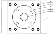
As Fig. 1, shown in Figure 3, be the die and the drip molding doffer of the utility model pull and stretch mould bases, it is made up of die block 3, die 5, blank 6, blank holder 7, slotted pan head screw 4, hexagon-headed bolt 17, cushion block 2, die shoe 1, interior hexagonal cylinder head bolt 18, interior hexagonal cylinder head bolt 19, plain washer 22, spring washer 23, hex nut 24, turret head king-bolt 25 and pressing plate 26.At first die 5 is put into the centre bore the inside of die block 3, blank 6 is placed on the upper surface of die 5, and 4 hexagon-headed bolts 17 of blank holder 7 usefulness are fixed on the upper surface of die block 3.By adjusting the tightness of 4 hexagon-headed bolts 17, can control the size of the pressure-pad-force of blank holder, to satisfy the forming requirements of different metal sheet metal deep drawing spare.Die block 3 is provided with 4 M10 screwed holes 20, is respectively charged into 4 slotted pan head screws 4, by adjusting the height of slotted pan head screw 4, can control the gap between blank holder 7 and the die 5, is shaped with the metal sheet material deep-drawing that adapts to different-thickness.4 bights of die block 3 are separately fixed at the upper end of 4 cushion blocks 2 with interior hexagonal cylinder head bolt 18, and the lower end of 4 cushion blocks 2 is die shoes 1, respectively die shoe 1 is connected with 4 cushion blocks 2 with interior hexagonal cylinder head bolt 19 equally.In order to prevent that cushion block 2 from rotating, be connected with 2 interior hexagonal cylinder head bolts 18 between each cushion block 2 and the die block 3, be connected with 2 interior hexagonal cylinder head bolts 19 between each cushion block 2 and the die shoe 1.4 cushion blocks 2 are supporting die block 3, and the cavity of formation is used for the blanking of formation of parts, as Fig. 4.
Fig. 5, Fig. 6 are the die shoe of the utility model pull and stretch mould bases and fixedlying connected of hydraulic press workbench, and whole die and drip molding doffer are fixed on above the workbench 27 of four-column hydraulic press.The right and left of die shoe 1 is being pressed with a block pressur plate 26 respectively, and the two ends of every block pressur plate 26 are fixed in above the workbench 27 of four-column hydraulic press with turret head king-bolt 25 respectively.The head of 4 turret head king-bolts 25 is contained in 4 T type groove 28 the insides of the workbench 27 of four-column hydraulic press respectively, and afterbody is fastening with it with hex nut 24.Loosening in order to prevent hex nut 24, before hex nut 24 is installed, put into plain washer 22 earlier, put into spring washer 23 again, at last hex nut 24 is tightened.
Sequence of movement during whole mould bases pull and stretch is:
------fixedly blank holder 7, and---punch 8 is descending with moved cross beam, and------punch 8 is up, and---the taking-up formation of parts---sheds blank holder 7---, and operation repeats drawing and forming to adjust the height of slotted pan head screw 4 to place blank 6.
The utility model is used for the pull and stretch mould bases of common four-column hydraulic press, can carry out the production of the metal sheet material deep-drawing spare of difformity and different size.This Drawing Die shelf structure is simple, easy to operate, cheap, and highly versatile is reliable and stable.Can replace the pull and stretch experiential function of double action hydraulic press through the common four-column hydraulic press after the repacking.
Claims (5)
1. pull and stretch mould bases that is used for common four-column hydraulic press, comprise punch fixture and die and drip molding doffer, it is characterized in that: described punch fixture is punch retainer (11) and upper bolster (12) to be fixedly mounted on below the moved cross beam of four-column hydraulic press with 4 turret head king-bolts (16), the head of 4 turret head king-bolts (16) is placed in 4 T type grooves of moved cross beam, and afterbody is fastening with hex nut (15); The right and left of the die shoe of described die and drip molding doffer (1) uses pressing plate (26) fixing respectively, the two ends of pressing plate (26) are fixed in above the workbench (27) of four-column hydraulic press with turret head king-bolt (25), the head of 4 turret head king-bolts (25) is placed on respectively in 4 T type grooves (28) of making platform (27), and afterbody is fastening with hex nut (24); Punch fixture and die and drip molding doffer are on same axis.
2. the pull and stretch mould bases of common four-column hydraulic press according to claim 1, it is characterized in that: the centre bore of punch sleeve (10) being put into punch retainer (11), upper bolster (12) be pressed in punch retainer (11) above, punch (8) inserts punch sleeve (10), and is with hexagon-headed bolt (9) that it is fastening.
3. the pull and stretch mould bases of common four-column hydraulic press according to claim 1; it is characterized in that: the termination portion of the punch (8) relative with die and drip molding doffer is provided with punch steam vent (21); there is a tapered plane die shank and hexagon-headed bolt (9) contact site, prevents that punch from trackslipping.
4. the pull and stretch mould bases of common four-column hydraulic press according to claim 1 is characterized in that: adjust gap between control die (5) and the blank holder (7) by being installed in 4 uniform, symmetrical slotted pan head screws (4) on the die block (3); By adjusting the tightness of 4 hexagon-headed bolts (17), the size of control pressure-pad-force.
5. the pull and stretch mould bases of common four-column hydraulic press according to claim 1, it is characterized in that: die and drip molding doffer adopt 4 cushion blocks (2) to support die block (3), cushion block (2) is connected with 2 interior hexagonal cylinder head bolts (18) with die block (3), and cushion block (2) is connected with 2 interior hexagonal cylinder head bolts (19) with die shoe (1).
Priority Applications (1)
| Application Number | Priority Date | Filing Date | Title |
|---|---|---|---|
| CN2010201539045U CN201644605U (en) | 2010-04-08 | 2010-04-08 | Deep drawing mould frame for common four-column hydraulic press |
Applications Claiming Priority (1)
| Application Number | Priority Date | Filing Date | Title |
|---|---|---|---|
| CN2010201539045U CN201644605U (en) | 2010-04-08 | 2010-04-08 | Deep drawing mould frame for common four-column hydraulic press |
Publications (1)
| Publication Number | Publication Date |
|---|---|
| CN201644605U true CN201644605U (en) | 2010-11-24 |
Family
ID=43109802
Family Applications (1)
| Application Number | Title | Priority Date | Filing Date |
|---|---|---|---|
| CN2010201539045U Expired - Fee Related CN201644605U (en) | 2010-04-08 | 2010-04-08 | Deep drawing mould frame for common four-column hydraulic press |
Country Status (1)
| Country | Link |
|---|---|
| CN (1) | CN201644605U (en) |
Cited By (6)
| Publication number | Priority date | Publication date | Assignee | Title |
|---|---|---|---|---|
| CN103990700A (en) * | 2014-05-21 | 2014-08-20 | 洛阳理工学院 | Male die with exhaust hole |
| CN104550483A (en) * | 2015-01-30 | 2015-04-29 | 辽宁奥斯福科技有限公司 | Aluminum alloy inner container reverse stretching mold and aluminum alloy inner container reverse stretching process |
| CN105458093A (en) * | 2015-12-25 | 2016-04-06 | 陈丽梅 | Temperature difference deep drawing die for stainless steel products |
| CN106334755A (en) * | 2016-09-13 | 2017-01-18 | 中国电子科技集团公司第四十八研究所 | Grating plate forming die |
| CN106975698A (en) * | 2017-04-12 | 2017-07-25 | 苏州汇程精密模具有限公司 | A kind of cup drawing diel |
| CN108500188A (en) * | 2018-03-27 | 2018-09-07 | 邓州市良机锻压设备制造有限公司 | A kind of special forging equipment of coal mine hydraulic supporting cylinder barrel and forging method |
-
2010
- 2010-04-08 CN CN2010201539045U patent/CN201644605U/en not_active Expired - Fee Related
Cited By (7)
| Publication number | Priority date | Publication date | Assignee | Title |
|---|---|---|---|---|
| CN103990700A (en) * | 2014-05-21 | 2014-08-20 | 洛阳理工学院 | Male die with exhaust hole |
| CN104550483A (en) * | 2015-01-30 | 2015-04-29 | 辽宁奥斯福科技有限公司 | Aluminum alloy inner container reverse stretching mold and aluminum alloy inner container reverse stretching process |
| CN105458093A (en) * | 2015-12-25 | 2016-04-06 | 陈丽梅 | Temperature difference deep drawing die for stainless steel products |
| CN106334755A (en) * | 2016-09-13 | 2017-01-18 | 中国电子科技集团公司第四十八研究所 | Grating plate forming die |
| CN106975698A (en) * | 2017-04-12 | 2017-07-25 | 苏州汇程精密模具有限公司 | A kind of cup drawing diel |
| CN108500188A (en) * | 2018-03-27 | 2018-09-07 | 邓州市良机锻压设备制造有限公司 | A kind of special forging equipment of coal mine hydraulic supporting cylinder barrel and forging method |
| CN108500188B (en) * | 2018-03-27 | 2024-08-23 | 邓州市良机锻压设备制造有限公司 | Forging equipment and forging method special for coal mine hydraulic support cylinder barrel |
Similar Documents
| Publication | Publication Date | Title |
|---|---|---|
| CN201644605U (en) | Deep drawing mould frame for common four-column hydraulic press | |
| CN105478539A (en) | Plate multipoint progressive forming device | |
| CN202062006U (en) | Segment bolt forming die | |
| CN207787448U (en) | A kind of cooperative mechanical is quick-moving to change combination cold punching die device | |
| CN105013928A (en) | Single-power multi-mold punching machine | |
| CN201543737U (en) | Hydraulic shell-nosing device for self-locking nut | |
| CN202316693U (en) | Large-scale bending machine with upper die convenient to replace | |
| CN203917655U (en) | Progressive die raw material surface oil dripping lubrication device | |
| CN202356510U (en) | Die structure capable of realizing punching and hole flanging on lateral wall of oil tank | |
| CN204340247U (en) | A kind of frame type hydraulic press | |
| CN204108203U (en) | A kind of consubstantiality double-station forging processing unit (plant) | |
| CN103447449A (en) | Mechanism suitable for off-line quick die change of multistage cold former | |
| CN207914381U (en) | A kind of press bed for distribution box door | |
| CN210498175U (en) | Trimming and stripping mechanism suitable for hot die forging of pistons with different diameters | |
| CN202623354U (en) | Ejection device for press | |
| CN211727191U (en) | Stamping die | |
| CN103521593A (en) | Automatic blanking die of sheet metal part | |
| CN203578560U (en) | Automatic ejection bending die | |
| CN207479312U (en) | A kind of improved trapezoidal solid valve mold | |
| CN202910155U (en) | Hole stamping die for thick materials | |
| CN102962335B (en) | A kind of large-scale insert type blanking die | |
| CN201950301U (en) | Tapping device of tapping and forming integrated production line | |
| CN203390018U (en) | Adjustable U-shaped workpiece punching device | |
| CN104043715A (en) | Upper arm bracket reinforcing plate blanking die | |
| CN202826456U (en) | Four-column universal hydraulic press |
Legal Events
| Date | Code | Title | Description |
|---|---|---|---|
| C14 | Grant of patent or utility model | ||
| GR01 | Patent grant | ||
| C17 | Cessation of patent right | ||
| CF01 | Termination of patent right due to non-payment of annual fee |
Granted publication date: 20101124 Termination date: 20130408 |