CN201487327U - 一种安全型燃气阀 - Google Patents
一种安全型燃气阀 Download PDFInfo
- Publication number
- CN201487327U CN201487327U CN2009201605190U CN200920160519U CN201487327U CN 201487327 U CN201487327 U CN 201487327U CN 2009201605190 U CN2009201605190 U CN 2009201605190U CN 200920160519 U CN200920160519 U CN 200920160519U CN 201487327 U CN201487327 U CN 201487327U
- Authority
- CN
- China
- Prior art keywords
- piston
- valve body
- fuel gas
- gas valve
- air outlet
- Prior art date
- Legal status (The legal status is an assumption and is not a legal conclusion. Google has not performed a legal analysis and makes no representation as to the accuracy of the status listed.)
- Expired - Lifetime
Links
Images


Abstract
本实用新型公开了一种安全型燃气阀,该安全型燃气阀其阀身上设有进气孔和出气孔,其中,进气孔设置在阀身一侧,阀身的另一侧设有带出气孔的调节杆,阀身后端设置有一带密封圈的密封杆,密封杆后端与顶簧配合,其前端穿过固定管前端的环形孔顶在带密封圈的活塞上,活塞同时配合有一定位机构。所述的定位机构由压簧和卡块构成,其中,卡块设置于活塞侧面,其下端与压簧相连,活塞中部开设有与卡块配合的卡槽。所述的出气孔位于调节杆前端,并呈水滴状。本实用新型在出现燃气压力过大的情况时,活塞可移动,使密封杆随之移动,其上的密封圈可以封闭气腔,阻断燃气通道,从而达到自动关闭燃气阀的目的,安全性非常好。
Description
技术领域:
本实用新型涉及燃气灶具技术领域,尤其是涉及一种燃气灶具上使用的燃气阀。
背景技术:
燃气灶具皆设有燃气阀,燃气从燃气阀的进气孔处进入,从出气孔处输出。由于燃气阀使用过程中可能出现燃气压力过大的情况,如不及时关闭阀门,将造成很大的安全隐患,而现有的燃气阀在这方面存在设计缺陷。
实用新型内容:
本实用新型的目的在于针对现有技术存在的不足之处而提供一种安全型燃气阀,它可以在燃气压力过大时自动关闭,安全性较高。
为实现上述目的,本实用新型的安全型燃气阀,其阀身上设有进气孔和出气孔,其中,进气孔设置在阀身一侧,阀身的另一侧设有带出气孔的调节杆,阀身后端设置有一带密封圈的密封杆,密封杆后端与顶簧配合,其前端穿过固定管前端的环形孔顶在带密封圈的活塞上,活塞同时配合有一定位机构。
所述的定位机构由压簧和卡块构成,其中,卡块设置于活塞侧面,其下端与压簧相连,活塞中部开设有与卡块配合的卡槽。
所述的出气孔位于调节杆前端,并呈水滴状。
本实用新型的有益效果在于:它在出现燃气压力过大的情况时,活塞可移动,使密封杆随之移动,其上的密封圈可以封闭气腔,阻断燃气通道,从而达到自动关闭燃气阀的目的,安全性非常好。
附图说明:
下面结合附图对本实用新型做进一步的说明:
附图1为本实用新型的剖视结构图;
附图2为本实用新型转动45度后的剖视结构图;
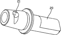
附图3为本实用新型的调节杆结构示意图。
具体实施方式:
以下所述仅为本实用新型的较佳实施例,并不因此而限定本实用新型的保护范围。
见附图1所示:本实用新型的安全型燃气阀,其阀身10上设有进气孔11和出气孔12,其中,进气孔11设置在阀身10一侧,阀身10的另一侧设有带出气孔21的调节杆20,转动调节杆20至其上的出气孔21与出气孔12相对时,燃气可从出气孔12排出。阀身10后端设置有一带密封圈31的密封杆30,密封杆30后端与顶簧42配合,其前端穿过固定杆30前端的环形孔31顶在带密封圈51的活塞50上,活塞50同时配合有一定位机构,该定位机构由压簧61和卡块62构成,其中,卡块62设置于活塞50侧面,其下端与压簧61相连,活塞40中部开设有与卡块62配合的卡槽52。
本实用新型在使用过程中,当出现燃气压力过大的情况时,燃气的压力冲向活塞50上的密封圈51,推动活塞50整体向右移动;当移动到一定位置时,卡块62受到压簧61的弹力作用向上顶起而卡入活塞50侧面的卡槽52内。同时,密封杆40带动密封圈41也向右移动,密封圈41封住环形孔31,使气腔得以封闭,燃气通道被阻断,从而达到自动关闭燃气阀的目的。
Claims (3)
1.一种安全型燃气阀,其阀身(10)上设有进气孔(11)和出气孔(12),其中,进气孔(11)设置在阀身(10)一侧,其特征在于:阀身(10)的另一侧设有带出气孔(21)的调节杆(20),阀身(10)后端设置有一带密封圈(31)的密封杆(30),密封杆(30)后端与顶簧(42)配合,其前端穿过固定杆(30)前端的环形孔(31)顶在带密封圈(51)的活塞(50)上,活塞(50)同时配合有一定位机构。
2.根据权利要求1所述的安全型燃气阀,其特征在于:所述的定位机构由压簧(61)和卡块(62)构成,其中,卡块(62)设置于活塞(50)侧面,其下端与压簧(61)相连,活塞(50)中部开设有与卡块(62)配合的卡槽(52)。
3.根据权利要求1或2所述的安全型燃气阀,其特征在于:所述的出气孔(21)位于调节杆(20)前端,并呈水滴状。
Priority Applications (1)
| Application Number | Priority Date | Filing Date | Title |
|---|---|---|---|
| CN2009201605190U CN201487327U (zh) | 2009-06-26 | 2009-06-26 | 一种安全型燃气阀 |
Applications Claiming Priority (1)
| Application Number | Priority Date | Filing Date | Title |
|---|---|---|---|
| CN2009201605190U CN201487327U (zh) | 2009-06-26 | 2009-06-26 | 一种安全型燃气阀 |
Publications (1)
| Publication Number | Publication Date |
|---|---|
| CN201487327U true CN201487327U (zh) | 2010-05-26 |
Family
ID=42426206
Family Applications (1)
| Application Number | Title | Priority Date | Filing Date |
|---|---|---|---|
| CN2009201605190U Expired - Lifetime CN201487327U (zh) | 2009-06-26 | 2009-06-26 | 一种安全型燃气阀 |
Country Status (1)
| Country | Link |
|---|---|
| CN (1) | CN201487327U (zh) |
Cited By (2)
| Publication number | Priority date | Publication date | Assignee | Title |
|---|---|---|---|---|
| CN103742684A (zh) * | 2013-12-25 | 2014-04-23 | 卢致英 | 一种改进的弹簧式卡式阀 |
| CN107941295A (zh) * | 2017-11-22 | 2018-04-20 | 重庆陆吾科技有限公司 | 一种结构简单的煤气表防爆装置 |
-
2009
- 2009-06-26 CN CN2009201605190U patent/CN201487327U/zh not_active Expired - Lifetime
Cited By (2)
| Publication number | Priority date | Publication date | Assignee | Title |
|---|---|---|---|---|
| CN103742684A (zh) * | 2013-12-25 | 2014-04-23 | 卢致英 | 一种改进的弹簧式卡式阀 |
| CN107941295A (zh) * | 2017-11-22 | 2018-04-20 | 重庆陆吾科技有限公司 | 一种结构简单的煤气表防爆装置 |
Similar Documents
| Publication | Publication Date | Title |
|---|---|---|
| CN201487327U (zh) | 一种安全型燃气阀 | |
| CN204345034U (zh) | 一种压缩天然气用先导式电磁阀 | |
| CN201934649U (zh) | 一种压力储水桶 | |
| CN113775802A (zh) | 一种直拉式管道燃气自闭阀 | |
| CN209671683U (zh) | 具有泄压功能的止逆阀 | |
| CN201706018U (zh) | 可调吸力磁铁超流控制阀 | |
| CN204201202U (zh) | 一种新型减压阀 | |
| CN101749461B (zh) | 无须外配导管的丝扣型倒流防止器 | |
| CN205618750U (zh) | 一种用于医疗系统的具有便于维修功能的供气终端装置 | |
| CN203717324U (zh) | 高压水泵站阀 | |
| CN206017899U (zh) | 一种升降式止回阀 | |
| CN201982674U (zh) | 气动活塞式启闭阀 | |
| CN204345008U (zh) | 管道燃气安全自闭阀 | |
| CN205036864U (zh) | 密封调节阀座装置 | |
| CN203730860U (zh) | 流量调节止回阀 | |
| CN103727306A (zh) | 减压器 | |
| CN203404534U (zh) | 快速拆装且拆后自动止水的水管连接结构 | |
| CN201916143U (zh) | 液压手动泵 | |
| CN201636391U (zh) | 燃气自闭球阀 | |
| CN204153231U (zh) | 天然气升降式止回阀 | |
| CN201715049U (zh) | 内螺纹止回球阀 | |
| CN210318548U (zh) | 一种带有检修密封锁定装置的双密封进水蝶阀 | |
| CN202900356U (zh) | 一种进气门中部结构 | |
| CN212004417U (zh) | 一种具有泄压功能的气嘴 | |
| CN205504106U (zh) | 一种限压阀 |
Legal Events
| Date | Code | Title | Description |
|---|---|---|---|
| C14 | Grant of patent or utility model | ||
| GR01 | Patent grant | ||
| CX01 | Expiry of patent term |
Granted publication date: 20100526 |
|
| CX01 | Expiry of patent term |