CN201433319Y - Cloth baking equipment - Google Patents
Cloth baking equipment Download PDFInfo
- Publication number
- CN201433319Y CN201433319Y CN2009200469875U CN200920046987U CN201433319Y CN 201433319 Y CN201433319 Y CN 201433319Y CN 2009200469875 U CN2009200469875 U CN 2009200469875U CN 200920046987 U CN200920046987 U CN 200920046987U CN 201433319 Y CN201433319 Y CN 201433319Y
- Authority
- CN
- China
- Prior art keywords
- cooling air
- heat exchange
- exchange layers
- air
- air channels
- Prior art date
- Legal status (The legal status is an assumption and is not a legal conclusion. Google has not performed a legal analysis and makes no representation as to the accuracy of the status listed.)
- Expired - Fee Related
Links
Images


Classifications
-
- D—TEXTILES; PAPER
- D06—TREATMENT OF TEXTILES OR THE LIKE; LAUNDERING; FLEXIBLE MATERIALS NOT OTHERWISE PROVIDED FOR
- D06F—LAUNDERING, DRYING, IRONING, PRESSING OR FOLDING TEXTILE ARTICLES
- D06F58/00—Domestic laundry dryers
- D06F58/20—General details of domestic laundry dryers
- D06F58/24—Condensing arrangements
Abstract
The utility model relates to cloth baking equipment, which comprises a machine barrel, a condensing device, a fan and a heating passage, wherein a rolling drum used for accommodating clothes is arranged in the machine barrel, and the heating passage is connected with the machine barrel for forming an air circulating passage. The condensing device comprises at least one baking air passage and at least one cooling air passage, wherein the baking air passage is communicated with the air circulating passage, the cooling air passage is communicated with external air and is respectively in adjacentconnection with the baking air passage, and heat exchange layers are arranged in the cooling air passage. The heat exchange layers in at least one cooling air passage are divided into first parts andsecond parts, wherein the heat dissipation areas of the first parts are larger than those of the second parts. Because the heat exchange layers have different heat dissipation areas, the heat exchangelayers can respectively correspond to different circulating air flow rates, the distribution and the dissipation of heat are uniform, and the condensing effect is improved.
Description
Technical field
The present invention relates to a kind of cloth drying device, relate in particular to the condensing unit of cloth drying device.Wherein, condensing unit comprises at least one the oven dry air duct that communicates with air circulation duct, also comprise with outside air and communicate and at least one adjacent with described oven dry air duct respectively cooling air channels, in the described cooling air channels heat exchange layers is housed.
Background technology
Existing dryer and collection laundry and clothes drying function are that the cloth drying devices such as clothes washer-dryer of one have following drying course usually: under the effect of heater, dry air is heated to form dry hot-air in heating tube, entering clothing then handles in the bucket and wet clothing generation heat exchange, moisture in the clothing is taken away, form relatively moister hot-air, go up set outlet through clothing processing bucket then and enter condensing unit, condensation through condensing unit, moisture in the relatively moister hot-air is condensed into water, discharge through drainpipe then, and the air after being condensed becomes the cold air of relatively dry, effect at fan is imported in the heating tube again, enter next circulation through the hot-air that adds the thermosetting drying, so go round and begin again, finish until drying procedure.
According to the difference of cooling medium, there is multiple condensing unit.The patent No. be DE3738031C2 German patent publication a kind of condensing unit that utilizes air as cooling medium.Adopt air to comprise at least one oven dry air duct usually as the condensing unit of cooling medium, also comprise communicate with outside air and respectively with at least one adjacent cooling air channels of oven dry air duct, heat exchange layers is housed in the cooling air channels.Handle the moist relatively thermal air current overbaking dry air passage that bucket is discharged from clothing, with the heat exchange layers in the heat transferred cooling air channels.During outside air process cooling air channels, take away the heat on the heat exchange layers, again from the condensing unit device for transferring.
Can find by experiment, often inhomogeneous through the damp-heat air distribution of oven dry air duct, so the distribution of heat on heat exchange layers is also inhomogeneous, influenced heat exchanger effectiveness.
Summary of the invention
At above problem, the purpose of this utility model is to provide a kind of improved cloth drying device, and the condensing unit heat that it comprised distributes evenly, and condensation effect is superior.
In order to reach above purpose, the utility model is realized by following technological means: a kind of cloth drying device comprises: a machine bucket, in adorn a cylinder that is used for accommodating laundry; Condensing unit, fan and heat tunnel and machine bucket are connected to form an air circulation duct.Condensing unit comprises at least one the oven dry air duct that communicates with air circulation duct, also comprise communicate with outside air and respectively with at least one adjacent cooling air channels of oven dry air duct, heat exchange layers is housed in the cooling air channels.Heat exchange layers at least one cooling air channels is divided into first and second portion at least, and wherein the area of dissipation of first is greater than the area of dissipation of second portion.
Because heat exchange layers has the zone of different area of dissipations, then can correspond respectively to different circulating air flows, the distribution that makes heat with distribute evenly, thereby improve condensation effect.
As a kind of preferable implementation of the utility model, a separator bar is arranged between described first and the second portion, this separator bar is roughly along vertical distribution of drying air duct.The distribution of the air-flow in this distribution mode and the air circulation duct is corresponding.
Replenish as of the present utility model, the circulating air in the air circulation duct is during through the oven dry air duct, through the flow of institute of the first correspondence position of heat exchange layers in the cooling air channels greater than with flow through second portion institute correspondence position.
As the preferable implementation of another kind of the present utility model, condensing unit comprises a hot switching path combination and a circulating air gatherer that is connected with the hot switching path combination, the outlet that described circulating air gatherer comprises an inlet that is connected with the machine bucket and is connected with hot switching path, described inlet is near first side of cooling air channels, second side away from cooling air channels, the second portion of heat exchange layers is near first side of cooling air channels in the described cooling air channels, and the first of heat exchange layers is near second side of cooling air channels in the described cooling air channels.Because the inlet of circulating air gatherer is near first side of cooling air channels, when circulating air enters the oven dry air duct from the inlet inflow of circulating air gatherer and by its outlet, the air-flow that the part of second side of close cooling air channels distributes is more, temperature is also higher, and the air-flow that the part of first side of close cooling air channels distributes is less, and temperature is lower.Said structure makes heat evenly to be distributed.
As the preferable implementation of another kind of the present utility model, the second portion of heat exchange layers is provided with the heat exchanging fin of proper alignment in the described cooling air channels, and there is staggered heat exchanging fin in society of described first.Staggered heat exchanging fin resistance is big, and airflow direction is variable, so all directions good fluidity, air-flow distributes more even, and heat exchange area is big.The heat exchanging fin resistance of proper alignment is little, and airflow direction is immutable, and heat exchange area is little.
Description of drawings
Fig. 1 is the organigram of cloth drying device;
Fig. 2 is the operation principle schematic diagram of condensing unit among Fig. 1;
Fig. 3 is the structural representation of condensing unit among Fig. 1, and wherein the shell of heat exchange layers is removed, to show the architectural feature of heat exchange layers;
Fig. 4 is the schematic diagram of the second portion of heat exchange layers among Fig. 3;
Fig. 5 is the schematic diagram of the first of heat exchange layers among Fig. 3.
The specific embodiment
As shown in Figure 1, cloth drying device 10 comprises the cylinder 14 that 12, one in a machine bucket can rotate by motor-driven and is loaded in the machine bucket 12.Pending clothing is carried out in cylinder 14 and is dried.Numerous through holes (not showing on the figure) are arranged on the wall of cylinder 14, spatially communicate with machine bucket 12 by these through hole cylinders 14.Machine bucket 12 is connected successively with condensing unit 16, fan 18 and heat tunnel 20, forms an air circulation duct 22.The circulating air that is used for drying clothes circulates in air circulation duct 22, takes away the moisture in the clothing.
Particularly, the workflow of cloth drying device 10 is as follows: circulating air enters cylinder 14 after heat tunnel 20 heating, with wherein wet clothing generation heat exchange, the moisture in the clothing is taken away, and forms more damp and hotter air.Damp and hot circulating air slave bucket 12 enters condensing unit 16.Through the condensation of condensing unit 16, the moisture in the more damp and hotter circulating air is condensed into water, inflow machine bucket 12, and finally discharge through drainage system 24.And the oven dry air after being condensed is imported in the heat tunnel 20 under the effect of fan 18 again, enters next circulation.
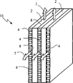
As shown in Figure 2.Condensing unit 16 comprises by partition wall 8 isolated mutually oven dry air duct 2 and cooling air channels 4.Oven dry air duct 2 and cooling air channels 4 distribute alternately.The heat exchange layers of being made up of a plurality of heat exchanging fins 6 wherein is housed in the cooling air channels 4.When circulating air 3 flows through temperature is passed to partition wall 8 from oven dry air duct 2, and then pass to heat exchange layers 6 by partition wall 8.Cold air 5 passes from heat exchange layers 6, takes away the most of heat on the heat exchange layers 6, thereby plays the cooling effect to damp-heat air 3.
As shown in Figure 3, condensing unit 16 comprises the combination 40 of hot switching path and makes up the 40 circulating air gatherers 42 that are connected with one with hot switching path.Circulating air gatherer 42 comprises an inlet 44 that is connected with machine bucket 12 and makes up 40 outlets that are connected 46 with hot switching path.Inlet 44 is near first side 48 of cooling air channels 4, away from second side 50 of cooling air channels 4.So circulating air 3 44 enters circulating air gatherer 42 and flows into and when entering oven dry air duct 2 by its outlet 46 from entering the mouth, the air-flow that the part of second side 50 of close cooling air channels 4 distributes is more, temperature is also higher, and the air-flow that the part of first side 48 of close cooling air channels 4 distributes is less, and temperature is lower.
Distribute for the heat that makes circulating air 3 can access more uniformly, the heat exchange layers in the cooling air channels 46 is divided into first 54 and second portion 56 along separator bar 52, the area of dissipation of first 54 is greater than the area of dissipation of second portion 56.Wherein roughly vertical distribution of edge oven dry air duct 2 of separator bar 52, and first side 48 of second portion 56 close cooling air channels 4, first 54 is near second side 50 of cooling air channels 4.
Learn by experiment, in the condensing unit 16 of said structure, it is about 3/5 that the air-flow that circulating air 3 distributes near the part of second side 50 of cooling air channels 4 in oven dry air duct 2 accounts for, and accounts for about 2/5 near the air-flow of the part distribution of first side 48 of cooling air channels 4.Therefore, the first 54 of heat exchange layers 6 accounts for the about 3/5 of heat exchange layers 6 gross areas in the cooling air channels 4, and the second portion 56 of heat exchange layers 6 accounts for about 2/5 of heat exchange layers 6 gross areas in the cooling air channels 4.
In other embodiments, if inlet 44 distribution arrangements of circulating air gatherer 42 are different with the position, then circulating air 3 distributes also different in oven dry air duct 2.Need design the first 54 of heat exchange layers 6 and the distribution form and the ratio of second portion 56 according to the concrete distribution situation of circulating air 3 in oven dry air duct 2.For example, if the inlet 44 of circulating air gatherer 42 is positioned at the bottom near oven dry air duct 2 centers, then circulating air 3 is bigger in the core flow distribution of oven dry air duct 2, therefore the part with big area of dissipation of heat exchange layers 6 should be distributed in the central area, and the part with less area of dissipation should be distributed in two side positions.
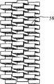
As a kind of embodiment wherein, as Fig. 4 and shown in Figure 5, the second portion 56 of heat exchange layers 6 is provided with the heat exchanging fin 58 of proper alignment in the cooling air channels 4, and there is staggered heat exchanging fin 58 in 54 societies of first.Heat exchanging fin 58 is made by Heat Conduction Material, and preferably has the spatial form of comparison rule, is convenient to air and circulates from a direction.Staggered heat exchanging fin 58 resistances are big, and airflow direction is variable, so all directions good fluidity, air-flow distributes more even, and heat exchange area is big.And heat exchanging fin 58 resistances of proper alignment are little, and airflow direction is immutable, and heat exchange area is little.
Except above-mentioned embodiment, heat exchange layers 6 can also have other a variety of specific embodiment.For example, first's 54 per unit volumes of heat exchange layers 6 have the area that more contacts with air than second portion 56, and are closeer as the heat exchanging fin bending, perhaps adopt heat exchange silk etc. in first 54.
The above embodiment of lifting only is better embodiment of the present invention, the present invention can also have many other embodiments, for the person of ordinary skill of the art, that is done under instruction of the present invention changes at equivalence of the present invention, must be included in the scope that claim of the present invention advocates.
Claims (6)
1. cloth drying device comprises:
A machine bucket (12), in adorn a cylinder (14) that is used for accommodating laundry;
A condensing unit (16), a fan (18) and a heat tunnel (20) are connected to form an air circulation duct (22) with described machine bucket (12);
Wherein, described condensing unit (16) comprises at least one the oven dry air duct (2) that communicates with air circulation duct (22), also comprise with outside air and communicate and adjacent with described oven dry air duct (2) respectively at least one cooling air channels (4), heat exchange layers (6) is housed in the described cooling air channels (4);
It is characterized in that: the heat exchange layers (6) at least one cooling air channels (4) is divided into first (54) and second portion (56) at least, and wherein the area of dissipation of first (54) is greater than the area of dissipation of second portion (56).
2. cloth drying device according to claim 1 is characterized in that: between described first (54) and the second portion (56) separator bar (52) is arranged, this separator bar (52) is roughly along vertical distribution of drying air duct (2).
3. cloth drying device according to claim 1 and 2, it is characterized in that: circulating air (3) in the air circulation duct (22) is during through oven dry air duct (2), through the flow of institute of first (54) correspondence position of heat exchange layers (6) in the cooling air channels (4) greater than with flow through second portion (56) institute correspondence position.
4. cloth drying device according to claim 3, it is characterized in that: described condensing unit (16) comprises a hot switching path combination (40) and a circulating air gatherer (42) that is connected with hot switching path combination (40), described circulating air gatherer (42) comprises an inlet (44) that is connected with machine bucket (12) and the outlet (46) that is connected with hot switching path combination (40), described inlet (44) is near first side (48) of cooling air channels (4), second side (50) away from cooling air channels (4), the second portion (56) of heat exchange layers (6) is near first side (48) of cooling air channels (4) in the described cooling air channels (4), and the first (54) of heat exchange layers (6) is near second side (50) of cooling air channels (4) in the described cooling air channels (4).
5. cloth drying device according to claim 4, it is characterized in that: the first (54) of heat exchange layers (6) accounts for the about 3/5 of heat exchange layers (6) gross area in the described cooling air channels (4), and described second portion (56) accounts for about 2/5 of heat exchange layers (6) gross area.
6. cloth drying device according to claim 3, it is characterized in that: the second portion (56) of heat exchange layers (6) is provided with the heat exchanging fin (58) of proper alignment in the described cooling air channels (4), and described first (54) is provided with staggered heat exchanging fin (58).
Priority Applications (4)
| Application Number | Priority Date | Filing Date | Title |
|---|---|---|---|
| CN2009200469875U CN201433319Y (en) | 2009-07-06 | 2009-07-06 | Cloth baking equipment |
| PL10727743T PL2452009T3 (en) | 2009-07-06 | 2010-07-01 | Clothes drying apparatus |
| PCT/EP2010/059331 WO2011003795A1 (en) | 2009-07-06 | 2010-07-01 | Clothes drying apparatus |
| EP10727743.6A EP2452009B1 (en) | 2009-07-06 | 2010-07-01 | Clothes drying apparatus |
Applications Claiming Priority (1)
| Application Number | Priority Date | Filing Date | Title |
|---|---|---|---|
| CN2009200469875U CN201433319Y (en) | 2009-07-06 | 2009-07-06 | Cloth baking equipment |
Publications (1)
| Publication Number | Publication Date |
|---|---|
| CN201433319Y true CN201433319Y (en) | 2010-03-31 |
Family
ID=42052129
Family Applications (1)
| Application Number | Title | Priority Date | Filing Date |
|---|---|---|---|
| CN2009200469875U Expired - Fee Related CN201433319Y (en) | 2009-07-06 | 2009-07-06 | Cloth baking equipment |
Country Status (4)
| Country | Link |
|---|---|
| EP (1) | EP2452009B1 (en) |
| CN (1) | CN201433319Y (en) |
| PL (1) | PL2452009T3 (en) |
| WO (1) | WO2011003795A1 (en) |
Cited By (6)
| Publication number | Priority date | Publication date | Assignee | Title |
|---|---|---|---|---|
| CN102477687A (en) * | 2010-11-26 | 2012-05-30 | 博西华电器(江苏)有限公司 | Clothes drying equipment |
| CN103486876A (en) * | 2013-06-21 | 2014-01-01 | 无锡小天鹅股份有限公司 | Heat exchange device and clothes-drying machine or washing-drying integrated machine thereof |
| WO2014094333A1 (en) * | 2012-12-21 | 2014-06-26 | 无锡小天鹅股份有限公司 | Clothes dryer |
| CN104911881A (en) * | 2014-03-14 | 2015-09-16 | 海尔集团公司 | Air condensation structure |
| CN105780424A (en) * | 2014-12-17 | 2016-07-20 | 无锡小天鹅股份有限公司 | Clothes dryer and heat exchange device of same |
| DE102017211840A1 (en) | 2016-07-21 | 2018-01-25 | BSH Hausgeräte GmbH | Condensation Dryer |
Families Citing this family (1)
| Publication number | Priority date | Publication date | Assignee | Title |
|---|---|---|---|---|
| CN104911882B (en) * | 2014-03-14 | 2018-10-30 | 青岛海尔滚筒洗衣机有限公司 | A kind of dryer or washing-drying integral machine |
Family Cites Families (3)
| Publication number | Priority date | Publication date | Assignee | Title |
|---|---|---|---|---|
| KR100459136B1 (en) * | 2002-08-21 | 2004-12-03 | 엘지전자 주식회사 | structure for arrangement cooling pin in condenser for condensing type clothes drier |
| JP2006026407A (en) * | 2004-07-20 | 2006-02-02 | Samsung Electronics Co Ltd | Drum washing machine |
| KR101235193B1 (en) * | 2005-06-13 | 2013-02-20 | 삼성전자주식회사 | Washing machine and control method thereof |
-
2009
- 2009-07-06 CN CN2009200469875U patent/CN201433319Y/en not_active Expired - Fee Related
-
2010
- 2010-07-01 WO PCT/EP2010/059331 patent/WO2011003795A1/en active Application Filing
- 2010-07-01 EP EP10727743.6A patent/EP2452009B1/en active Active
- 2010-07-01 PL PL10727743T patent/PL2452009T3/en unknown
Cited By (8)
| Publication number | Priority date | Publication date | Assignee | Title |
|---|---|---|---|---|
| CN102477687A (en) * | 2010-11-26 | 2012-05-30 | 博西华电器(江苏)有限公司 | Clothes drying equipment |
| WO2014094333A1 (en) * | 2012-12-21 | 2014-06-26 | 无锡小天鹅股份有限公司 | Clothes dryer |
| CN103486876A (en) * | 2013-06-21 | 2014-01-01 | 无锡小天鹅股份有限公司 | Heat exchange device and clothes-drying machine or washing-drying integrated machine thereof |
| CN103486876B (en) * | 2013-06-21 | 2016-01-13 | 无锡小天鹅股份有限公司 | Heat-exchanger rig and dryer thereof or washing-drying integral machine |
| CN104911881A (en) * | 2014-03-14 | 2015-09-16 | 海尔集团公司 | Air condensation structure |
| CN104911881B (en) * | 2014-03-14 | 2019-01-22 | 青岛海尔滚筒洗衣机有限公司 | A kind of air setting structure |
| CN105780424A (en) * | 2014-12-17 | 2016-07-20 | 无锡小天鹅股份有限公司 | Clothes dryer and heat exchange device of same |
| DE102017211840A1 (en) | 2016-07-21 | 2018-01-25 | BSH Hausgeräte GmbH | Condensation Dryer |
Also Published As
| Publication number | Publication date |
|---|---|
| PL2452009T3 (en) | 2015-04-30 |
| WO2011003795A1 (en) | 2011-01-13 |
| EP2452009B1 (en) | 2014-09-10 |
| EP2452009A1 (en) | 2012-05-16 |
Similar Documents
| Publication | Publication Date | Title |
|---|---|---|
| CN201433319Y (en) | Cloth baking equipment | |
| JP6069797B2 (en) | Heat exchanger for clothes drying condensation, clothes drying means, clothes dryer, and clothes drying method | |
| KR102100473B1 (en) | Clothes treating apparatus with a waste heat recovery means | |
| CN101903584A (en) | clothes drying device with heat pump | |
| CN103015140A (en) | Clothes dryer | |
| KR20080098860A (en) | Drying apparatus | |
| CN202116898U (en) | Drying machine | |
| CN105200747A (en) | Clothes dryer | |
| CN105316919A (en) | Tumble dryer and drying method | |
| JP2018515192A (en) | Clothing condensation dryer and clothing condensation drying method | |
| CN106256942A (en) | Baker and manufacture method thereof | |
| CN210425798U (en) | Multistage heat recovery air-source heat pump drying equipment | |
| EP3257425B1 (en) | Dish-washing machine | |
| CN103266458B (en) | Washing machine drum and the roller washing machine with it | |
| CN102071564A (en) | Heating device and clothes drying apparatus employing same | |
| CN201648804U (en) | Heat exchanger for air condensing type clothes drying machine | |
| KR20170110120A (en) | Air condenser and clothes dryer | |
| CN105332252A (en) | Roller clothes dryer | |
| KR100598383B1 (en) | Washing machine | |
| CN102477687A (en) | Clothes drying equipment | |
| CN106676855B (en) | Drying washing machine | |
| CN201433318Y (en) | Cloth baking equipment | |
| CN212983382U (en) | Clothes drying equipment | |
| CN108332514A (en) | A kind of microwave drying system | |
| KR20150124353A (en) | Clothes dryer |
Legal Events
| Date | Code | Title | Description |
|---|---|---|---|
| C14 | Grant of patent or utility model | ||
| GR01 | Patent grant | ||
| CF01 | Termination of patent right due to non-payment of annual fee |
Granted publication date: 20100331 Termination date: 20140706 |
|
| EXPY | Termination of patent right or utility model |