CN201415295Y - Five-axis multifunctional thread grinding machining center - Google Patents
Five-axis multifunctional thread grinding machining center Download PDFInfo
- Publication number
- CN201415295Y CN201415295Y CN2009200538536U CN200920053853U CN201415295Y CN 201415295 Y CN201415295 Y CN 201415295Y CN 2009200538536 U CN2009200538536 U CN 2009200538536U CN 200920053853 U CN200920053853 U CN 200920053853U CN 201415295 Y CN201415295 Y CN 201415295Y
- Authority
- CN
- China
- Prior art keywords
- axle
- guide rail
- servomotor
- slide plate
- grinding
- Prior art date
- Legal status (The legal status is an assumption and is not a legal conclusion. Google has not performed a legal analysis and makes no representation as to the accuracy of the status listed.)
- Expired - Fee Related
Links
Images


Landscapes
- Grinding Of Cylindrical And Plane Surfaces (AREA)
Abstract
The utility model discloses a five-axis multifunctional thread grinding machining center which belongs to numerical control machine tool field and is composed of a machine tool body, a Z direction sliding plate, an electric work piece spindle, an X direction bottom plate, an upright column, a Y direction sliding plate, an A axis revolving stage and an electric grinding spindle. A Z direction servomotor drives a Z direction lead screw to drive the Z direction sliding plate to move in Z direction, the upright column is arranged on the X direction guide rail sliding block, an X direction servomotor drives an X direction lead screw to drive the upright column to move in X direction, a Y direction guide rail is fixedly mounted on the upright column, the Y direction sliding plate is mounted on aY direction guide rail sliding block, a Y direction servomotor motor drives a Y direction lead screw to drive the Y direction sliding plate to move in Y direction, an electric work piece spindle is arranged on the Z direction sliding plate, the A axis revolving stage is arranged on the Y direction sliding plate, the A axis revolving stage is connected with an A axis servomotor, and the electric grinding spindle is fixed on the A axis revolving workbench through thread connection; the five-axis multifunctional thread grinding machining center adopts the five-axis structure, simplifies the machine tool structure, realizes the grinding of an ultra-long nut, extends the adaptability of the machine tool and reduces the manufacturing cost.
Description
Technical field:
The present invention's five shaft multifunctional thread grinding machining centers belong to the Digit Control Machine Tool field, particularly relate to a kind of multi-functional composite processing machine tool of the feed screw nut's of being adapted to grinding.
Background technology:
Screw mandrel is the critical function parts of precise numerical control machine, and ball nut is the most important building block of screw mandrel, the quality of ball nut quality is the precision and the feel of decision screw mandrel directly, during existing ball nut grinding lathe grinding inner roller path of ball nut, interior raceway only depends on the operative employee to estimate assurance with the relative position that goes back to the hole of bead, can't stablize the assurance product quality at all; Comparatively advanced now ball nut grinding center is a three-shaft linkage internal thread grinding center, and also there is following subject matter in it when having than high manufacturing accuracy: machinable ball nut specification is smaller, can not process the bigger nut of diameter or length; Process different nuts, need adjust the pivot angle of truer and the pivot angle of internal thread grinding electricity main shaft manually; Problems such as operation, clamping are convenient inadequately; Can only adopt emery wheel correction emery wheel, different nuts needs different emery wheels, use cost height.And existing state-of-the-art four or five spindle nut grinding centers scope applicatory are narrow, can only process small-sized nut, can only the machining large nut, screw mandrel manufacturer is if make the feed screw nut of various models, just need to buy the grinding center of multiple different model, cost of investment is bigger.
Summary of the invention:
The purpose of invention is that for avoiding the deficiencies in the prior art part, providing a kind of has than high manufacturing accuracy, can process the ball nut of plurality of specifications, operation, convenient mounting and clamping, the five shaft multifunctional thread grinding machining centers that use cost is little.
The objective of the invention is to reach by following measure, five shaft multifunctional thread grinding machining centers of main axle moving formula have adopted five axle construction, are made up of to slide plate, A axle panoramic table, grinding electricity main shaft, emery wheel tool magazine, truer, centre frame and tailstock etc. to base plate, column, Y to slide plate, workpiece electricity main shaft, X lathe bed, Z.
Z is fixed on the lathe bed to guide rail, Z is installed to screw mandrel on lathe bed, Z connects Z to screw mandrel to servomotor, Z is installed in Z on the guide rail slide block to slide plate, Z is connected by nut seat with nut on the leading screw to the guide rail slide block, Z is connected on the lathe bed to the guide rail slide block to guide rail and Z by Z to slide plate, and Z, drives Z and is Z to moving to slide plate to leading screw to driven by servomotor Z;
X is fastened on the lathe bed by bolt to base plate, X is installed in X on base plate to guide rail, X is installed to screw mandrel on lathe bed, X connects X to screw mandrel to servomotor, X is connected by nut seat with nut on the leading screw to the guide rail slide block, and to screw mandrel, column is arranged on X on the guide rail slide block to X to driven by servomotor X, X, drives column and is X to moving to screw mandrel to driven by servomotor X;
Y is fixedly mounted on the column to guide rail, Y is installed to screw mandrel on column, Y connects Y to screw mandrel to servomotor, Y is connected by nut seat with nut on the leading screw to the guide rail slide block, Y is installed in Y on screw mandrel to the guide rail slide block, and Y is installed in Y on the guide rail slide block to slide plate, Y, drives Y and is Y to moving to slide plate to screw mandrel to driven by servomotor Y;
At Z workpiece electricity main shaft is set on slide plate, workpiece electricity main shaft forms the C axle around the rotation of Z axle and rotatablely moves, and workpiece electricity main shaft is provided with locking device;
Z is vertical mutually to base plate with X to slide plate,
A axle panoramic table is arranged on Y on slide plate by precision bearing, and A axle panoramic table connects A axle servomotor, and A axle servomotor rotates formation A axle by the turbine and worm transmission around X-axis and rotatablely moves.A axle panoramic table adopts the static pressure rotary table, is provided with locking device on A axle panoramic table;
Grinding electricity main shaft is fastened on the A axle rotary table by bolt, and grinding electricity main shaft has to move forward and backward with column is X to motion, moves up and down to slide plate with Y and is Y to motion, does the A axle with the rotation of A axle workbench and moves;
The tool magazine support is set on lathe bed, and the emery wheel tool magazine is arranged on the lathe bed by the tool magazine support, and the crusher lab setting is in the outer side edges of column.Adopting manipulator that emery wheel electricity main shaft is carried out emery wheel changes;
Truer is arranged on the main spindle box of workpiece electricity main shaft, and emery wheel is revised;
In 5 above-mentioned coordinates, X, Y, three axles of Z are linear axis, do rectilinear motion, two axles of A, C are rotating shaft, rotate, three linear axis all adopt the linear grating chi to carry out the control of full cut-off ring, and two rotating shafts all adopt round grating to carry out the control of full cut-off ring.
The present invention has increased A axle and Y-axis, and the combination of A axle and Y-axis can make the emery wheel center be adjusted to the nut axis, and the length of internal thread mill bar can realize the grinding of overlength nut without limits.The A axle can make the internal thread grinding wheel spindle swing automatically, need not be manual, and convenient the use.A axle of the present invention can be rocked to horizontal level automatically, so its main shaft of emery wheel correction just need not pendulum angle, has simplified machine tool structure.Simultaneously can X and the interpolation of Z axle realize the correction of emery wheel profile.Both can adopt the emery wheel correcting mode, also can adopt the mode of numerical control interpolation correction.Adopt Buddha's warrior attendant dish wheel numerical control interpolation correction, cancelled emery wheel, a kind of dish wheel just can satisfy the grinding of all nuts, and is very convenient, and cost reduces.
The present invention can be provided with centre frame, at Z centre frame is set on slide plate; Make things convenient for long nut processing.
The present invention can be provided with tailstock, at Z tailstock is set on slide plate; Can the grinding external screw thread, so it is again an external thread grinder, lathe function has obtained expansion.
Five shaft multifunctional thread grinding machining center operators of main axle moving formula of the present invention are near apart from workpiece, and operational measure is very convenient.
Its course of work of the present invention is as follows: lathe starts, the grinding electricity main shaft that workpiece electricity main shaft that the Z of Z direction motion rotatablely moves to slide plate, C direction to the Y of the column of slide plate, directions X motion, the motion of Y direction and A direction rotatablely move moves to lathe zero point, start the procedure of finishing in advance, each parts of lathe will be by instruction operation automatically, after truer was revised emery wheel, grinding was processed to workpiece.Because the grinding tool magazine can be installed nearly 24 kinds of different emery wheels at most, the feed screw nut can a clamping and finish whole grinding process; When requiring to finish the complex space curve surface grinding, the grinding to the complex space curved surface is finished in X, Y, Z, C, A five-axle linkage; When the workpiece grinding only need grinding electricity main shaft after angle of A axle rotation pendulum when motionless, because the rotary table indoor design has locking device, locking device starts A axle panoramic table is locked, and the rigidity of grinding electricity main shaft is strengthened, vibrations reduce, and grinding quality improves; When workpiece need not to rotate when the workpiece grinding, because the design of workpiece electricity main shaft has locking device, locking device started, and workpiece electricity main shaft is locked, and the rigidity of workpiece electricity main shaft is strengthened, and vibrations reduce, and grinding quality and grinding accuracy improve.After the completion of processing, each returns to dead-center position, and workpiece electricity main shaft and grinding electricity main shaft stop operating, and wait for the processing of next workpiece.
The present invention's five shaft multifunctional thread grinding machining centers have following characteristics:
1, the present invention has adopted five axle construction, and the A axle can make the internal thread grinding wheel spindle swing automatically, need not be manual, the convenient use, the combination of A axle and Y-axis makes the emery wheel center be adjusted to the nut axis, the length of internal thread mill bar can realize the grinding of overlength nut without limits.
2, during correction internal thread main shaft emery wheel of the present invention, the A axle can be rocked to horizontal level automatically, has simplified machine tool structure.Can X and the interpolation of Z axle realize the correction of emery wheel profile, can adopt the emery wheel correcting mode, also can adopt the mode of numerical control interpolation correction, very convenient, cost reduces.
3, the present invention is provided with centre frame, makes things convenient for long nut processing, and tailstock is set, and has expanded lathe function, enlarges the applicability of lathe, reduces manufacturing cost.
Description of drawings
Accompanying drawing 1 is the schematic diagram of structure of the present invention.
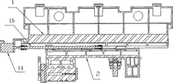
Accompanying drawing 2 is front views of structure of the present invention.
Accompanying drawing 3 is side views of structure of the present invention.
Accompanying drawing 4 is vertical views of structure of the present invention.
Accompanying drawing 5a is an A axle rotary table profile of the present invention.
Accompanying drawing 5b is an A axle rotary table profile of the present invention.
Accompanying drawing 6 is profiles of workpiece electricity main shaft of the present invention.
Accompanying drawing 7 is that X of the present invention is to profile.
Accompanying drawing 8 is that Z of the present invention is to profile.
The specific embodiment
The invention will be further described below in conjunction with accompanying drawing.
Among the figure: 1, lathe bed, 2, Z is to slide plate, and 3, workpiece electricity main shaft, 4, X is to base plate, and 5, column, 6, Y is to slide plate, 7, A axle panoramic table, 8, the emery wheel tool magazine, 9, grinding electricity main shaft, 10, truer, 11, centre frame, 12, tailstock, 13, grinding tool magazine support, 14, Z axle servomotor, 15, Z is to ball screw, 16, the work spindle locking device, 17, X is to guide rail 18, Y is to ball screw, and 19, X is to ball screw, 20, Y is to servomotor, 21, Z is to guide rail, and 22, workpiece, 23, A axle servomotor 24, Y is to guide rail 25, turbine and worm pair 26, Z is to the guide rail slide block, 27, X is to servomotor, 28, X is to guide rail slide block, 29, Y is to guide rail slide block, 30, A axle panoramic table locking device.
Shown in accompanying drawing 1, accompanying drawing 2, accompanying drawing 3, accompanying drawing 4, main axle moving formula five shaft multifunctional thread grinding machining centers mainly are made up of to functional parts such as slide plate 6, A axle panoramic table 7, emery wheel tool magazine 8, grinding electricity main shaft 9, truer 10, centre frame 11 and tailstocks 12 to base plate 4, column 5, Y to slide plate 2, workpiece electricity main shaft 3, X lathe bed 1, Z.Z to slide plate 2 and X to base plate 3 orthogonal being arranged on the lathe bed 1, wherein X is fastened on the lathe bed 1 to base plate 4 by bolt, Z is connected on the lathe bed 1 to guide rail slide block 25 to guide rail 21 and Z by Z to slide plate 2, and is Z to moving at Z under the driving of ball-screw 15 to servomotor 14 and Z; Workpiece electricity main shaft 3, centre frame 11 and tailstock 12 are arranged on Z on slide plate 2; Workpiece electricity main shaft 3 also can form the C axle around the rotation of Z axle and rotatablely move except being Z with Z to moving to slide plate 2, and 3 designs of workpiece electricity main shaft have locking device 16; Column 5 is connected to slide block 28 with X to guide rail 17 by X and is arranged on X on base plate 4, and is X to moving at X under the driving of ball-screw 19 to servomotor 27 and X; Y is connected to guide rail slide block 29 with Y to guide rail 24 by Y to slide plate 6 and is arranged on the column 5, and is Y to moving at Y under the driving of ball-screw 18 to servomotor 20 and Y; A axle panoramic table 7 is arranged on Y on slide plate 6 by precision bearing, and under the driving of A axle servomotor 23, by secondary 25 transmissions of turbine and worm, the A axle rotates formation A axle around X-axis and rotatablely moves, A axle panoramic table 7 adopts the static pressure rotary table, and design has locking device 30; Grinding electricity main shaft 9 is fastened on the A axle rotary table 7 by bolt, and grinding electricity main shaft 9 has to move forward and backward with column 5 is X to motion, moves up and down to slide plate 6 with Y and is Y to motion, does the A axle with 7 rotations of A axle workbench and moves; Emery wheel tool magazine 8 is arranged on the lathe bed 1 by tool magazine support 13 and is positioned at the outer side edges of column 5, adopts manipulator that grinding electricity main shaft 9 is carried out emery wheel and changes; Truer 10 is arranged on the main spindle box of workpiece electricity main shaft 3, and emery wheel is revised.
Its course of work is: lathe starts, the A axle workbench 7 that workpiece electricity main shaft 3 that the Z of Z direction motion rotatablely moves to slide plate 6, C direction to the Y of the column 5 of slide plate 2, directions X motion, the motion of Y direction and A direction rotatablely move moves to lathe zero point, start the procedure of finishing in advance, each parts of lathe will be by instruction operation automatically, 8 pairs of grinding electricity of emery wheel tool magazine main shaft 9 carries out tool changing, after 10 pairs of emery wheels of truer were revised, 22 grindings were processed to workpiece.Because emery wheel tool magazine 8 can be installed nearly 24 emery wheels at most, feed screw nut's workpiece 22 can a clamping and finish whole grinding process; When requiring to finish the complex space curve surface grinding, the grinding to the complex space curved surface is finished in X, Y, Z, C, A five-axle linkage; When the workpiece grinding only need grinding electricity main shaft 9 after angle of A axle rotation pendulum when motionless, because the rotary table indoor design has locking device 30, locking device 30 starts A axle panoramic table 7 is locked, and the rigidity of grinding electricity main shaft 9 is strengthened, vibrations reduce, and grinding quality improves; When workpiece 22 need not to rotate when the workpiece grinding, because 3 designs of workpiece electricity main shaft have locking device 16, locking device 16 started, and workpiece electricity main shaft 3 is locked, and the rigidity of workpiece electricity main shaft is strengthened, and vibrations reduce, and grinding quality and grinding accuracy improve.After the completion of processing, each returns to dead-center position, and workpiece electricity main shaft and grinding electricity main shaft stop operating, and wait for the processing of next workpiece.
As accompanying drawing 5a, shown in the accompanying drawing 5b, A axle panoramic table 7 of the present invention is arranged on Y on slide plate 6 by precision bearing, A axle panoramic table connects A axle servomotor 23, A axle servomotor rotates formation A axle by secondary 25 transmissions of turbine and worm around X-axis and rotatablely moves, A axle panoramic table adopts the static pressure rotary table, on A axle panoramic table, be provided with A axle panoramic table locking device 30, grinding electricity main shaft is fastened on the A axle rotary table by bolt, grinding electricity main shaft has to move forward and backward with column is X to motion, move up and down to slide plate with Y and to be Y, do the A axle with the rotation of A axle workbench and move to motion.
As shown in Figure 6, the present invention is provided with workpiece electricity main shaft 3 at Z on slide plate 2, and workpiece electricity main shaft forms the C axle around the rotation of Z axle and rotatablely moves, and workpiece electricity main shaft is provided with work spindle locking device 16.
As shown in Figure 7, X of the present invention is fastened on the lathe bed by bolt to base plate 4, and X is installed in X on screw mandrel to the guide rail slide block, and X drives X to ball screw 19 to servomotor 27, and column 5 is arranged on X on the guide rail slide block, drives column and is X to moving; Y is installed in Y on the guide rail slide block to slide plate 6,, Y drives Y to ball screw 18 to servomotor 20, drives Y and is Y to moving to slide plate; A axle panoramic table 7 is arranged on Y on slide plate by precision bearing, grinding electricity main shaft 9 is fastened on the A axle rotary table by bolt, grinding electricity main shaft has to move forward and backward with column is X to motion, moves up and down to slide plate with Y and is Y to motion, does the A axle with the rotation of A axle workbench and moves.
As shown in Figure 8, Z of the present invention is connected on the lathe bed 1 to the guide rail slide block to guide rail and Z by Z to slide plate 2, and Z axle servomotor 14 drives Z to ball-screw 15, drives Z and is Z to moving to slide plate.
Claims (9)
1, a kind of five shaft multifunctional thread grinding machining centers, by lathe bed, Z is to slide plate, workpiece electricity main shaft, grinding electricity main shaft, X is to base plate, column is formed, Z is fixed on the lathe bed to guide rail, Z connects Z to screw mandrel to servomotor, Z is installed in Z on the guide rail slide block to slide plate, Z is connected by nut seat with nut on the leading screw to the guide rail slide block, Z to driven by servomotor Z to leading screw, drive Z and be Z to moving to slide plate, at Z workpiece electricity main shaft is set on slide plate, X is fastened on the lathe bed to base plate, X is installed in X on base plate to guide rail, X connects X to screw mandrel to servomotor, X is connected by nut seat with nut on the leading screw to the guide rail slide block, column is arranged on X on the guide rail slide block, X to driven by servomotor X to screw mandrel, drive column and be X to moving, it is characterized in that: Y is fixedly mounted on the column to guide rail, Y connects Y to screw mandrel to servomotor, and Y is connected by nut seat with nut on the leading screw to the guide rail slide block, and Y is installed in Y on the guide rail slide block to slide plate, Y to driven by servomotor Y to screw mandrel, drive Y and be Y to moving to slide plate, A axle panoramic table is arranged on Y on slide plate, and A axle panoramic table connects A axle servomotor.
2, five shaft multifunctional thread grinding machining centers according to claim 1, it is characterized in that: Z is vertical mutually to base plate with X to slide plate.
3, five shaft multifunctional thread grinding machining centers according to claim 1, it is characterized in that: A axle panoramic table is arranged on Y on slide plate by bearing, and A axle servomotor is by the turbine and worm transmission.
4, five shaft multifunctional thread grinding machining centers according to claim 1, it is characterized in that: A axle panoramic table static pressure rotary table is provided with locking device on A axle panoramic table.
5, five shaft multifunctional thread grinding machining centers according to claim 1 is characterized in that: workpiece electricity main shaft is provided with locking device.
6, five shaft multifunctional thread grinding machining centers according to claim 1 is characterized in that: grinding electricity main shaft is fastened on the A axle rotary table by bolt.
7, five shaft multifunctional thread grinding machining centers according to claim 1, it is characterized in that: the tool magazine support is set on lathe bed, and the emery wheel tool magazine is arranged on the lathe bed by the tool magazine support, in the outer side edges of column.
8, five shaft multifunctional thread grinding machining centers according to claim 1 is characterized in that: at Z centre frame is set on slide plate.
9, five shaft multifunctional thread grinding machining centers according to claim 1 is characterized in that: at Z tailstock is set on slide plate.
Priority Applications (1)
| Application Number | Priority Date | Filing Date | Title |
|---|---|---|---|
| CN2009200538536U CN201415295Y (en) | 2009-03-28 | 2009-03-28 | Five-axis multifunctional thread grinding machining center |
Applications Claiming Priority (1)
| Application Number | Priority Date | Filing Date | Title |
|---|---|---|---|
| CN2009200538536U CN201415295Y (en) | 2009-03-28 | 2009-03-28 | Five-axis multifunctional thread grinding machining center |
Publications (1)
| Publication Number | Publication Date |
|---|---|
| CN201415295Y true CN201415295Y (en) | 2010-03-03 |
Family
ID=41791704
Family Applications (1)
| Application Number | Title | Priority Date | Filing Date |
|---|---|---|---|
| CN2009200538536U Expired - Fee Related CN201415295Y (en) | 2009-03-28 | 2009-03-28 | Five-axis multifunctional thread grinding machining center |
Country Status (1)
| Country | Link |
|---|---|
| CN (1) | CN201415295Y (en) |
Cited By (6)
| Publication number | Priority date | Publication date | Assignee | Title |
|---|---|---|---|---|
| CN102528615A (en) * | 2011-11-25 | 2012-07-04 | 深圳市创造机电有限公司 | Glass fine grinding machine and grinding control method thereof |
| CN104923868A (en) * | 2015-06-30 | 2015-09-23 | 林建国 | Thread grinding mechanism |
| CN105364490A (en) * | 2015-12-27 | 2016-03-02 | 沈正福 | Five-axis numerical control machining center |
| CN105643018A (en) * | 2014-12-03 | 2016-06-08 | 鼎绅精机有限公司 | Sand clock type screw forming machining machine |
| CN114131420A (en) * | 2021-12-13 | 2022-03-04 | 山东源顺智能科技有限公司 | Multi-cutter switching multi-channel numerical control machine tool |
| CN114505697A (en) * | 2021-10-12 | 2022-05-17 | 枣庄北航机床创新研究院有限公司 | Side drive type slide block and swing rod multi-axis linkage numerical control machine tool |
-
2009
- 2009-03-28 CN CN2009200538536U patent/CN201415295Y/en not_active Expired - Fee Related
Cited By (10)
| Publication number | Priority date | Publication date | Assignee | Title |
|---|---|---|---|---|
| CN102528615A (en) * | 2011-11-25 | 2012-07-04 | 深圳市创造机电有限公司 | Glass fine grinding machine and grinding control method thereof |
| CN102528615B (en) * | 2011-11-25 | 2015-02-11 | 深圳市创造机电有限公司 | Glass fine grinding machine and grinding control method thereof |
| CN105643018A (en) * | 2014-12-03 | 2016-06-08 | 鼎绅精机有限公司 | Sand clock type screw forming machining machine |
| CN104923868A (en) * | 2015-06-30 | 2015-09-23 | 林建国 | Thread grinding mechanism |
| CN104923868B (en) * | 2015-06-30 | 2017-03-15 | 林建国 | grinding thread mechanism |
| CN105364490A (en) * | 2015-12-27 | 2016-03-02 | 沈正福 | Five-axis numerical control machining center |
| CN105364490B (en) * | 2015-12-27 | 2018-05-22 | 东莞创响智能科技有限公司 | Five-axis NC machine center |
| CN114505697A (en) * | 2021-10-12 | 2022-05-17 | 枣庄北航机床创新研究院有限公司 | Side drive type slide block and swing rod multi-axis linkage numerical control machine tool |
| CN114505697B (en) * | 2021-10-12 | 2023-06-09 | 枣庄北航机床创新研究院有限公司 | Side-driven type slide block swing rod multi-axis linkage numerical control machine tool |
| CN114131420A (en) * | 2021-12-13 | 2022-03-04 | 山东源顺智能科技有限公司 | Multi-cutter switching multi-channel numerical control machine tool |
Similar Documents
| Publication | Publication Date | Title |
|---|---|---|
| CN101513686B (en) | Five-axis multi-functional thread grinding machining center | |
| CN203092346U (en) | Ultra-hard abrasive wheel numerical-control accurate finishing grinder | |
| CN201415295Y (en) | Five-axis multifunctional thread grinding machining center | |
| CN206382849U (en) | A kind of new vertical Compositions of metal-working machines | |
| CN105269321B (en) | Composite processing machine tool and its method are thrown in blade digital control milling | |
| CN201086222Y (en) | Six-shaft abrasive belt grinding machine | |
| CN202264128U (en) | 6-axis linkage numerical-control belt grinding machine for grinding curved surfaces | |
| CN101791725B (en) | Spiral bevel gear and hypoid gear forming method large-gear grinding machine | |
| CN201685166U (en) | Numerically-controlled composite grinding center | |
| CN100537140C (en) | Grinding attachment suitable for freely curved face | |
| CN101508039A (en) | Six-axis five-linkage spiral taper gear cutting machine tool | |
| CN101342617A (en) | Four-shaft four-linkage numerical control spiral bevel gear milling machine arrangement | |
| CN208629237U (en) | A kind of three servo wheel dressers and its multi-functional compound grinding machine | |
| CN103418852B (en) | New and effective numerically controlled tooth grinding machine | |
| CN103203677A (en) | Numerically controlled grinder special for slewing bearing processing | |
| CN101569979A (en) | Processing method and processing center for detecting external thread on line | |
| CN101811277A (en) | Grinding device and using method thereof for ball bearing inner ring raceway | |
| CN213672273U (en) | Internal and external thread grinding machine with grinding wheel capable of being subjected to in-situ shape correction | |
| CN112059327B (en) | Internal and external thread grinder with grinding wheel capable of being shaped in situ | |
| CN201693436U (en) | Gantry milling and grinding machine | |
| CN112045539A (en) | Multipurpose numerically controlled grinder | |
| CN102179745A (en) | Numerical control vertical shaft round table composite grinding machine | |
| CN101579812B (en) | Method and processing center for external thread rotary milling and grinding | |
| CN212947098U (en) | Multipurpose numerically controlled grinder | |
| CN201592384U (en) | Ball bearing inner ring raceway grinding device |
Legal Events
| Date | Code | Title | Description |
|---|---|---|---|
| C14 | Grant of patent or utility model | ||
| GR01 | Patent grant | ||
| C17 | Cessation of patent right | ||
| CF01 | Termination of patent right due to non-payment of annual fee |
Granted publication date: 20100303 Termination date: 20120328 |