CN201344457Y - Intensive sunlight fiber-guided lighting device - Google Patents
Intensive sunlight fiber-guided lighting device Download PDFInfo
- Publication number
- CN201344457Y CN201344457Y CN 200920092805 CN200920092805U CN201344457Y CN 201344457 Y CN201344457 Y CN 201344457Y CN 200920092805 CN200920092805 CN 200920092805 CN 200920092805 U CN200920092805 U CN 200920092805U CN 201344457 Y CN201344457 Y CN 201344457Y
- Authority
- CN
- China
- Prior art keywords
- fixed
- box body
- daylighting
- daylighting box
- optical fiber
- Prior art date
- Legal status (The legal status is an assumption and is not a legal conclusion. Google has not performed a legal analysis and makes no representation as to the accuracy of the status listed.)
- Expired - Fee Related
Links
Images


Classifications
-
- F—MECHANICAL ENGINEERING; LIGHTING; HEATING; WEAPONS; BLASTING
- F21—LIGHTING
- F21S—NON-PORTABLE LIGHTING DEVICES; SYSTEMS THEREOF; VEHICLE LIGHTING DEVICES SPECIALLY ADAPTED FOR VEHICLE EXTERIORS
- F21S11/00—Non-electric lighting devices or systems using daylight
Landscapes
- Life Sciences & Earth Sciences (AREA)
- Sustainable Development (AREA)
- Engineering & Computer Science (AREA)
- General Engineering & Computer Science (AREA)
- Non-Portable Lighting Devices Or Systems Thereof (AREA)
- Photovoltaic Devices (AREA)
Abstract
The utility model provides an intensive sunlight fiber-guided lighting device, which is characterized in that an array of condenser lenses is fixed in a lighting box, a solar battery is fixed above the lighting box body, an optical fiber bundle interface is formed behind each condenser lens on the bottom surface of the lighting box, the other end of each optical fiber bundle is introduced into a light diffuser, the lighting box body is fixed on an autotracking U-shaped bracket, the transverse and longitudinal reducing motors of the U-shaped bracket are connected with a PLC chip, the output end of the solar panel is connected with the PLC chip, and the PLC controls the rotation of the motors so as to lead the lighting box body to rotate with the Sun. In the day time, though the intensive sunlight fiber-guided lighting device, the sunlight can be transferred through an optical fiber to the light diffuser to form a light source. Therefore, the utility model provides a practical device for making full use of solar energy.
Description
Technical field
The utility model relates to the fiber-optic illuminated technology.
Background technology
Solar energy is the huge energy of people's comparison exploitation, utilizing sunshine to be thrown light in the place of no daylighting condition also is a direction of human use's solar energy, at present, some laboratory results and relevant report are arranged in this respect both at home and abroad, but do not see specific product so far.
Summary of the invention
The purpose of this utility model is to provide a kind of natural daylight that utilizes the sun to provide the device of illumination for basement and the bad office of daylighting condition, to reach energy-conservation purpose.The technical solution of the utility model as shown in drawings, comprise that one is formed solar collector by a plurality of condenser lens array, it is characterized in that condenser lens array is fixed in the daylighting box body, daylighting box body upper fixed solar cell, the positive fixing self-cleaning transparent glass of daylighting box body, there is the fibre bundle interface back of each collector lens of daylighting box bottom surface, the termination of fibre bundle is fixed on and connects on the bayonet socket, and the cross section that makes the fibre bundle termination is on the focus of lens, the other end of all fibre bundles is incorporated in the astigmatism body, have in the astigmatism body and can form irreflexive rib body, daylighting box body crosswise fixed at one on motion tracking U type support, a reducing motor is arranged on one support arm of U type support, the output shaft of reducing motor is connected with daylighting box side, there is a rotating shaft corresponding position of another support arm, the termination of rotating shaft is connected with the side of daylighting box, the lower end of U type support is fixed on the output shaft of a longitudinal deceleration motor, the longitudinal deceleration motor is fixed on the pedestal, horizontal and vertical reducing motor is connected with a PLC chip, and the output of solar panel is connected with the PLC chip.When the utility model uses, longitude and latitude according to the locality, in 1 year daytime integral point constantly light collecting body be stored in the PLC chip over against the elevation data of sunlight, send the rotation of signal control motor by PLC, make the daylighting box body around transverse axis in miter angle, around the longitudinal axis 180 the degree in the rotation, guarantee that daylight substantially vertically impinges upon on the light collecting body, the electric power system that solar panel and battery constitute.Daylight can be sent to astigmatism body by optical fiber under the utility model situation by day and form light source, be specially adapted to the basement facility, can save a large amount of power supplys, be the device that makes full use of a practicality of solar energy.
Description of drawings
Accompanying drawing 1 is the utility model lighting equipment part front view;
Accompanying drawing 2 is Figure 1A-A cutaway view;
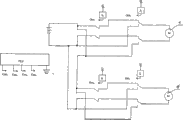
Accompanying drawing 3 is a sunlight collecting apparatus control circuit schematic diagram.
Legend: 1, solar panel, 2, collector lens, 3, the reducing motor on the support arm, 4, the longitudinal deceleration motor, 5, self-cleaning transparent glass, 6, fibre bundle, 7, astigmatism body.
The specific embodiment
Collector lens (2) specification is φ 30cm * 20cm, totally 9,3X3 arranges, and solar panel (1) is fixed on the top of daylighting box, above the daylighting box by self-cleaning transparent glass (5) capping that is coated with nanometer film, there are 9 at the bottom of the daylighting box and connect bayonet socket, 9 optical fiber converge into a fibre bundle (6), and insert in the astigmatism body (7) its termination, and astigmatism body is made of cloche and glass cone, the rib body is arranged in the glass cone, and the illumination that optical fiber transmits has constituted a light source on cone.Reducing motor (3) and longitudinal deceleration motor (4) slewing area are respectively miter angle and 180 degree angles.After tested, under normal illumination, present embodiment can satisfy the lighting demand of 100 square metres of basements, is equivalent to substitute 240 watts fluorescent lamp lighting.
Claims (1)
1, intensive day optical fiber is led lighting device, comprise that one is formed solar collector by a plurality of condenser lens array, it is characterized in that condenser lens array is fixed in the daylighting box body, daylighting box body upper fixed solar cell, the positive fixing self-cleaning transparent glass of daylighting box body, there is the fibre bundle interface back of each collector lens of daylighting box bottom surface, the termination of fibre bundle is fixed on and connects on the bayonet socket, and the cross section that makes the fibre bundle termination is on the focus of lens, the other end of all fibre bundles is incorporated in the astigmatism body, have in the astigmatism body and can form irreflexive rib body, daylighting box body crosswise fixed at one on motion tracking U type support, a reducing motor is arranged on one support arm of U type support, the output shaft of reducing motor is connected with daylighting box side, there is a rotating shaft corresponding position of another support arm, the termination of rotating shaft is connected with the side of daylighting box, the lower end of U type support is fixed on the output shaft of a longitudinal deceleration motor, the longitudinal deceleration motor is fixed on the pedestal, horizontal and vertical reducing motor is connected with a PLC chip, and the output of solar panel is connected with the PLC chip.
Priority Applications (1)
| Application Number | Priority Date | Filing Date | Title |
|---|---|---|---|
| CN 200920092805 CN201344457Y (en) | 2009-01-06 | 2009-01-06 | Intensive sunlight fiber-guided lighting device |
Applications Claiming Priority (1)
| Application Number | Priority Date | Filing Date | Title |
|---|---|---|---|
| CN 200920092805 CN201344457Y (en) | 2009-01-06 | 2009-01-06 | Intensive sunlight fiber-guided lighting device |
Publications (1)
| Publication Number | Publication Date |
|---|---|
| CN201344457Y true CN201344457Y (en) | 2009-11-11 |
Family
ID=41276039
Family Applications (1)
| Application Number | Title | Priority Date | Filing Date |
|---|---|---|---|
| CN 200920092805 Expired - Fee Related CN201344457Y (en) | 2009-01-06 | 2009-01-06 | Intensive sunlight fiber-guided lighting device |
Country Status (1)
| Country | Link |
|---|---|
| CN (1) | CN201344457Y (en) |
Cited By (6)
| Publication number | Priority date | Publication date | Assignee | Title |
|---|---|---|---|---|
| CN102384427A (en) * | 2010-05-28 | 2012-03-21 | 三菱电机株式会社 | Display/illumination system |
| CN102478203A (en) * | 2010-11-30 | 2012-05-30 | 西安大昱光电科技有限公司 | Novel indoor lighting system |
| CN102486284A (en) * | 2010-12-03 | 2012-06-06 | 西安中科麦特电子技术设备有限公司 | Novel solar illumination device |
| CN103527953A (en) * | 2013-10-22 | 2014-01-22 | 云南邦桥节能科技有限公司 | Illuminating lamp |
| CN107504451A (en) * | 2017-07-05 | 2017-12-22 | 西安理工大学 | A kind of passive natural light omnidirectional harvester and acquisition method |
| CN108351122A (en) * | 2016-09-15 | 2018-07-31 | 罗德路万公司 | The method for transmitting the solar energy focused |
-
2009
- 2009-01-06 CN CN 200920092805 patent/CN201344457Y/en not_active Expired - Fee Related
Cited By (6)
| Publication number | Priority date | Publication date | Assignee | Title |
|---|---|---|---|---|
| CN102384427A (en) * | 2010-05-28 | 2012-03-21 | 三菱电机株式会社 | Display/illumination system |
| CN102478203A (en) * | 2010-11-30 | 2012-05-30 | 西安大昱光电科技有限公司 | Novel indoor lighting system |
| CN102486284A (en) * | 2010-12-03 | 2012-06-06 | 西安中科麦特电子技术设备有限公司 | Novel solar illumination device |
| CN103527953A (en) * | 2013-10-22 | 2014-01-22 | 云南邦桥节能科技有限公司 | Illuminating lamp |
| CN108351122A (en) * | 2016-09-15 | 2018-07-31 | 罗德路万公司 | The method for transmitting the solar energy focused |
| CN107504451A (en) * | 2017-07-05 | 2017-12-22 | 西安理工大学 | A kind of passive natural light omnidirectional harvester and acquisition method |
Similar Documents
| Publication | Publication Date | Title |
|---|---|---|
| CN103032810B (en) | Intellectual solar fibre-optical laser mixed lighting device and control method thereof | |
| CN201344457Y (en) | Intensive sunlight fiber-guided lighting device | |
| CN2926790Y (en) | Sunlight-induced collecting illuminating system | |
| CN101237195A (en) | An optical overlapping solar power supply device | |
| CN205897587U (en) | Sunshine gatherer that possesses positive light automatic tracking | |
| CN201173416Y (en) | Positive electricity lighting device | |
| CN102997160A (en) | Solar street lamp | |
| CN201547659U (en) | Solar energy collection device with Fresnel convex lens | |
| CN203384874U (en) | Sunlight tracking illumination device | |
| CN103034245A (en) | Honeycomb type solar energy collecting device | |
| CN202997674U (en) | An off-grid concentrating photovoltaic power generation system | |
| CN102800731A (en) | Device for increasing solar energy illuminance | |
| CN204387931U (en) | A kind of solar street light | |
| CN209744257U (en) | High-efficient intelligent semiconductor road surface lighting device | |
| CN204127847U (en) | Light-focusing type solar photoelectric LED street lamp | |
| CN103856161A (en) | Sunlight lead-in and photovoltaic power generation integrated mechanism | |
| CN204665137U (en) | Automatically the wind and light complementary road lamp of phototropic face can be regulated | |
| CN203115817U (en) | Solar double-mode light-extraction system | |
| CN205351125U (en) | Energy -saving road lamp | |
| CN206145616U (en) | Sun automatic tracking lighting system based on optic fibre leaded light | |
| CN208705731U (en) | A kind of solar energy high-efficiency generation device | |
| TWI510733B (en) | Indoor illuminating device using directed sunlight | |
| CN103453434B (en) | Sunlight tracing illuminator | |
| CN202103608U (en) | Automatic track type solar energy utilization device | |
| CN201344638Y (en) | Solar energy fiber-guided heater |
Legal Events
| Date | Code | Title | Description |
|---|---|---|---|
| C14 | Grant of patent or utility model | ||
| GR01 | Patent grant | ||
| CF01 | Termination of patent right due to non-payment of annual fee | ||
| CF01 | Termination of patent right due to non-payment of annual fee |
Granted publication date: 20091111 Termination date: 20130106 |