CN201244440Y - Accident chiller for flue-gas desulfurizing device - Google Patents
Accident chiller for flue-gas desulfurizing device Download PDFInfo
- Publication number
- CN201244440Y CN201244440Y CNU2008201100755U CN200820110075U CN201244440Y CN 201244440 Y CN201244440 Y CN 201244440Y CN U2008201100755 U CNU2008201100755 U CN U2008201100755U CN 200820110075 U CN200820110075 U CN 200820110075U CN 201244440 Y CN201244440 Y CN 201244440Y
- Authority
- CN
- China
- Prior art keywords
- accident
- cooler
- pipe
- flue gas
- nozzle
- Prior art date
- Legal status (The legal status is an assumption and is not a legal conclusion. Google has not performed a legal analysis and makes no representation as to the accuracy of the status listed.)
- Expired - Lifetime
Links
Images

Abstract
The utility model relates to an accident cooler for a flue gas desulfurization device, comprising an inlet flue pipe of an absorption tower, a distribution pipe, a main pipe connected with the distribution pipe, branch pipes and nozzles. The distribution pipe and the main pipe are supported and arranged on the inlet flue pipe; the branch pipes are evenly distributed and vertically stretch downward into the inlet flue pipe from the upward side of the inlet flue pipe; each branch pipe is respectively provided with a nozzle; the nozzles can be of one group or two groups and are arranged above and below the horizontal axis of the inlet flue pipe at the one third diameter position of the inlet flue pipe. The utility model has the advantages and beneficial effects that because umbelliform water frog sprayed by a plurality of nozzles forms a water screen in a flue pipe when starting, high-temperature flue gas can be cooled to reduce the temperature when vertically passing through the water screen, thus realizing the aim of protecting the equipment in a tower. The utilization of the accident cooler strengthens the precaution to the desulfurization technic accident; the accident cooler has simple structure and low cost, can be widely applied to the wet flue gas desulfurization equipment and has higher practical value.
Description
Technical field
The utility model relates to wet process of FGD equipment, particularly a kind of accident cooler that is used for flue gas desulfur device.
Background technology
At present, when power station or Industrial Boiler adopted wet fuel gas desulfurizing technology, absorption tower and packed tower were nucleus equipments, and spraying layer in the tower, demister, filler and tower internals such as anticorrosion are organic material, and heat-resisting ability is limited.Usually, desulphurization plant is operated in 100 ℃-150 ℃.Under normal operation, hot flue gas can not cause damage to tower internals after being absorbed agent solution cooling, but runs into emergency case such as absorbent stop supplies, and the temperature of elevated temperature heat flue gas rises sharply, and when accident occurs, will certainly cause the damage to absorption tower equipment.
In view of the present situation that in industrial wet process of FGD equipment, lacks the strick precaution equipment of sulfur removal technology accident, take place for preventing accident, solve the safety problem of absorption tower equipment, the new problem of cooling device has been proposed.
The utility model content
The purpose of this utility model is to overcome above-mentioned defective, because the elevated temperature heat flue gas causes device damage, improves the absorption tower device security greatly, accident cooler simple in structure, with low cost when a kind of can trying to avert accidents is provided.
For achieving the above object, the utility model is used for the accident cooler of flue gas desulfur device, comprise the gas approach that is installed on the sidewall of absorption tower, also comprise sparge pipe and coupled main, described main is connected with a plurality of arms, described sparge pipe and main frame are contained on the described gas approach, each described arm evenly distributes and stretches into straight down the described gas approach from the gas approach top, each described arm is separately installed with nozzle, the water of described nozzle ejection forms umbrella, and constitutes the screen of water together in flue.
The utility model is used for the accident cooler of flue gas desulfur device, and wherein said sparge pipe is being equipped with water intaking valve with described main junction.
The utility model is used for the accident cooler of flue gas desulfur device, and wherein the outer wall of each described arm is provided with axial ribs.
The utility model is used for the accident cooler of flue gas desulfur device, and wherein said arm is connected by flange with described main.
The utility model is used for the accident cooler of flue gas desulfur device, and the quantity of wherein said arm is the 8-12 root.
The utility model is used for the accident cooler of flue gas desulfur device, and wherein said nozzle is 1 group, is installed in the end of described arm, and the height of described nozzle is positioned at 1/3 place of its diameter of described gas approach horizontal axis top.
The utility model is used for the accident cooler of flue gas desulfur device, and wherein said nozzle is 2 groups, is installed in the middle part and the end of described arm, and described nozzle lays respectively at 1/3 place of its diameter of described gas approach horizontal axis above and below.
Advantage and good effect that the utility model is used for the accident cooler of flue gas desulfur device are: owing to be provided with sparge pipe, main, arm and nozzle on the gas approach of industrial wet process of FGD equipment; the umbrella water smoke that is sprayed by a plurality of nozzles in flue when enabling constitutes the water screen; the flue gas of high temperature is cooled vertically by the water screen time, has reached the purpose of equipment in the protection tower.The strick precaution to the sulfur removal technology accident has been strengthened in the use of accident cooler, and its project organization is simple, and cost is low, can be widely used in wet process of FGD equipment, has higher utility.
To be elaborated with reference to accompanying drawing in conjunction with the embodiments down, so that the purpose of this utility model, feature and advantage are had deep understanding.
Description of drawings
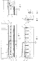
Fig. 1 is the vertical view that the utility model is used for the accident cooler of flue gas desulfur device;
Fig. 2 is the B-B cutaway view of Fig. 1;
Fig. 3 is the A-A cutaway view of Fig. 1;
Fig. 4 is the partial enlarged view of A among Fig. 3;
Fig. 5 is the C-C cutaway view of Fig. 4;
Fig. 6 is another B-B cutaway view of Fig. 1;
Fig. 7 is another A-A cutaway view of Fig. 1.
The specific embodiment
See figures.1.and.2, the accident cooler that is used for flue gas desulfur device that the utility model provides is installed on the gas approach 2 of absorption tower 1 sidewall, comprises sparge pipe 3, main 4, arm 5 and nozzle 8.With reference to Fig. 2,4 of sparge pipe 3 and mains are contained on the gas approach 2, and sparge pipe 3 is being equipped with water intaking valve 6 with main 4 junctions.With reference to Fig. 1 and Fig. 3, main 4 is connected with a plurality of arms 5, and with reference to Fig. 4, arm 5 is connected by flange 9 with main 4.With reference to Fig. 5, for fear of producing distortion at high-temperature flue gas lower branch line 5, the outer wall of arm 5 is provided with axial ribs 7.With reference to Fig. 2 and Fig. 3, each arm 5 evenly distributes and stretches into straight down the gas approach 2 from gas approach 2 tops, and each arm 5 is separately installed with nozzle 8, and the water of nozzle 8 ejections forms umbrella, and constitutes the screen of water together in flue.
Describe embodiment of the present utility model in detail below in conjunction with accompanying drawing.
With reference to Fig. 1 and Fig. 3, the utility model is used for the accident cooler of flue gas desulfur device, and the quantity of arm 5 is 9.The end of each arm 5 is equipped with 1 nozzle 8, is positioned at 1/3 place of its diameter of gas approach 2 horizontal axis top.
With reference to Fig. 6 and Fig. 7, be used for another embodiment of accident cooler of flue gas desulfur device at the utility model, the middle part of arm 5 and end are separately installed with 2 nozzles 8, lay respectively at 1/3 place of gas approach 2 its diameters of horizontal axis above and below.
When system runs into the absorbent cut-off or tower is gone under the too high situation of cigarette temperature; the accident cooler that startup the utility model is used for flue gas desulfur device comes into operation; water with certain pressure enters main 4 by sparge pipe 3; nozzle 8 through each arm 5 sprays again; form umbrella at the nozzle place; the umbrella of a plurality of nozzles constitutes the water screen in flue; shown in the dotted line among Fig. 3 and Fig. 7; at this moment; the cooling that just is cooled vertically by the water screen time of the flue gas of high temperature reduces the purpose that the cigarette temperature reaches equipment in the protection tower thus.The utility model accident cooler has been strengthened the strick precaution to the sulfur removal technology accident, and simple in structure, cost is low, can be widely used in wet process of FGD equipment, has higher utility.
Above-described embodiment is described preferred implementation of the present utility model; be not that scope of the present utility model is limited; relate under the prerequisite of spirit not breaking away from the utility model; various distortion and improvement that the common engineers and technicians in this area make the technical solution of the utility model all should fall in the definite protection domain of claims of the present utility model.
Claims (7)
1. accident cooler that is used for flue gas desulfur device, comprise the gas approach (2) that is installed on the sidewall of absorption tower (1), it is characterized in that: also comprise sparge pipe (3) and coupled main (4), described main (4) is connected with a plurality of arms (5), described sparge pipe (3) and main (4) frame are contained on the described gas approach (2), each described arm (5) evenly distributes and stretches into straight down the described gas approach (2) from gas approach (2) top, each described arm (5) is separately installed with nozzle (8), the water of described nozzle (8) ejection forms umbrella, and constitutes the screen of water together in flue.
2. the accident cooler that is used for flue gas desulfur device according to claim 1 is characterized in that: wherein said sparge pipe (3) is being equipped with water intaking valve (6) with described main (4) junction.
3. the accident cooler that is used for flue gas desulfur device according to claim 1 and 2 is characterized in that: wherein the outer wall of each described arm (5) is provided with axial ribs (7).
4. the accident cooler that is used for flue gas desulfur device according to claim 3 is characterized in that: wherein said arm (5) is connected by flange (9) with described main (4).
5. the accident cooler that is used for flue gas desulfur device according to claim 4 is characterized in that: the quantity of wherein said arm (5) is the 8-12 root.
6. the accident cooler that is used for flue gas desulfur device according to claim 5, it is characterized in that: wherein said nozzle (8) is 1 group, be installed in the end of described arm (5), the height of described nozzle (8) is positioned at 1/3 place of its diameter of described gas approach (2) horizontal axis top.
7. the accident cooler that is used for flue gas desulfur device according to claim 5, it is characterized in that: wherein said nozzle (8) is 2 groups, be installed in the middle part and the end of described arm (5), described nozzle (8) lays respectively at 1/3 place of its diameter of described gas approach (2) horizontal axis above and below.
Priority Applications (1)
| Application Number | Priority Date | Filing Date | Title |
|---|---|---|---|
| CNU2008201100755U CN201244440Y (en) | 2008-08-19 | 2008-08-19 | Accident chiller for flue-gas desulfurizing device |
Applications Claiming Priority (1)
| Application Number | Priority Date | Filing Date | Title |
|---|---|---|---|
| CNU2008201100755U CN201244440Y (en) | 2008-08-19 | 2008-08-19 | Accident chiller for flue-gas desulfurizing device |
Publications (1)
| Publication Number | Publication Date |
|---|---|
| CN201244440Y true CN201244440Y (en) | 2009-05-27 |
Family
ID=40728255
Family Applications (1)
| Application Number | Title | Priority Date | Filing Date |
|---|---|---|---|
| CNU2008201100755U Expired - Lifetime CN201244440Y (en) | 2008-08-19 | 2008-08-19 | Accident chiller for flue-gas desulfurizing device |
Country Status (1)
| Country | Link |
|---|---|
| CN (1) | CN201244440Y (en) |
Cited By (2)
| Publication number | Priority date | Publication date | Assignee | Title |
|---|---|---|---|---|
| CN102274685A (en) * | 2011-06-08 | 2011-12-14 | 宝钢工程技术集团有限公司 | Smoke wet desulphurization cooling device |
| CN109708490A (en) * | 2019-01-07 | 2019-05-03 | 安徽晋煤中能化工股份有限公司 | A kind of New Cycle water cooling system |
-
2008
- 2008-08-19 CN CNU2008201100755U patent/CN201244440Y/en not_active Expired - Lifetime
Cited By (3)
| Publication number | Priority date | Publication date | Assignee | Title |
|---|---|---|---|---|
| CN102274685A (en) * | 2011-06-08 | 2011-12-14 | 宝钢工程技术集团有限公司 | Smoke wet desulphurization cooling device |
| CN102274685B (en) * | 2011-06-08 | 2013-04-10 | 宝钢工程技术集团有限公司 | Smoke wet desulphurization cooling device |
| CN109708490A (en) * | 2019-01-07 | 2019-05-03 | 安徽晋煤中能化工股份有限公司 | A kind of New Cycle water cooling system |
Similar Documents
| Publication | Publication Date | Title |
|---|---|---|
| CN103759544A (en) | Low-moisture coke quenching and waste heat utilizing device | |
| CN201244440Y (en) | Accident chiller for flue-gas desulfurizing device | |
| CN203916446U (en) | Desulphurization denitration enriched flue gas cooling device | |
| CN202485142U (en) | Special humidifier for spinning room | |
| CN205598950U (en) | High -efficient low -cost flue gas desulphurization device | |
| CN202532515U (en) | Flue gas multilevel cooling device for flue gas desulfurization system | |
| CN202427345U (en) | Efficient energy-saving desulfuration deduster | |
| CN203355569U (en) | Inlet smoke uniform distribution device for wet desulphurization absorption tower | |
| CN216755901U (en) | Carbon dioxide collector | |
| CN106902629A (en) | Desulfurizing tower annular water-distributing device | |
| CN206361411U (en) | A kind of heat-conducting oil system head tank nitrogen protection device | |
| CN202516471U (en) | Desulfurizing device for industrial kiln flue gas | |
| CN204746006U (en) | Energy -efficient environmental protection dust collector | |
| CN104910952B (en) | Catalytic cracking apparatus stable absorption unit and desulfurization unit shutdown sealed relaying purging process | |
| CN205055802U (en) | Advection is compound desulfurization absorption tower against current | |
| CN203816496U (en) | Efficient flue gas desulfurization device | |
| CN206152551U (en) | Boiler desulfurization tower defroster | |
| CN2928215Y (en) | Gas-liquid distributor | |
| CN211216142U (en) | Flue type spray tower | |
| CN203321059U (en) | Single-sleeve-type chimney for power plant in high-wind-speed regions | |
| CN203303792U (en) | Integrated washing tower | |
| CN210448672U (en) | White-removing desulfurizing tower | |
| CN218924301U (en) | Boiler flue gas purification device | |
| CN204897951U (en) | Blast furnace stokehold dust removing facility | |
| CN216591773U (en) | A oxidation wind temperature reduction water saving fixtures for thermal power plant desulfurization system |
Legal Events
| Date | Code | Title | Description |
|---|---|---|---|
| C14 | Grant of patent or utility model | ||
| GR01 | Patent grant | ||
| EE01 | Entry into force of recordation of patent licensing contract |
Assignee: Beijing Longyuan Environment Protection Engineering Co., Ltd. Assignor: Chen Yule|Wang Xiaoli Contract record no.: 2011990000604 Denomination of utility model: Accident chiller for flue-gas desulfurizing device Granted publication date: 20090527 License type: Exclusive License Record date: 20110712 |
|
| CX01 | Expiry of patent term | ||
| CX01 | Expiry of patent term |
Granted publication date: 20090527 |