CN201243181Y - Connector - Google Patents
Connector Download PDFInfo
- Publication number
- CN201243181Y CN201243181Y CNU2008201344711U CN200820134471U CN201243181Y CN 201243181 Y CN201243181 Y CN 201243181Y CN U2008201344711 U CNU2008201344711 U CN U2008201344711U CN 200820134471 U CN200820134471 U CN 200820134471U CN 201243181 Y CN201243181 Y CN 201243181Y
- Authority
- CN
- China
- Prior art keywords
- semicanal
- connection
- buckle
- location
- connects
- Prior art date
- Legal status (The legal status is an assumption and is not a legal conclusion. Google has not performed a legal analysis and makes no representation as to the accuracy of the status listed.)
- Expired - Fee Related
Links
Images


Landscapes
- Bridges Or Land Bridges (AREA)
Abstract
The utility model discloses a connector, comprising a first connecting semi-pipe and a second connecting semi-pipe, one side ends of the first connecting semi-pipe and the second connecting semi-pipe are directly connected by a flexible connecting element, and the other side ends thereof are buckled and connected by a buckling component. The connector has the advantages of simple installing operation and convenient usage.
Description
Technical field
The utility model belongs to fastening connection technical field, is specifically related to a kind of connector.
Background technology
Traditional cable wiring generally all adopts the securing member auxiliary erection of screw and so on, the new wire laying mode that current trend is got up is cable to be contained in the isolated pipe lay, the pipe joints such as then adopting traditional threeway, four-way, five-way that is connected of pipeline and pipeline, but pipe joints such as traditional threeway, four-way, five-way are when being connected with pipeline, adopt is threaded more, its fitting operation is comparatively complicated, time and effort consuming.
The utility model content
The purpose of this utility model provide a kind of fitting operation comparatively simple, use connector comparatively easily.
The technical scheme that realizes the utility model purpose is: a kind of connector comprises that the first connection semicanal material is connected the semicanal material with second; The described first connection semicanal material is connected the semicanal material with described second a side directly connects by flexibly connecting element, and described first connects the semicanal material is fastened and connected by the buckle assembly with described second another side that is connected the semicanal material.
In the technique scheme, the described element that flexibly connects is a connecting plate, and the two ends of described connecting plate are separately positioned on the described first connection semicanal material and are connected on the semicanal material with described second; Described connecting plate passes through gluing, welding or is connected the semicanal material with described first by injection molding to be connected the connection of semicanal material with second.
In the technique scheme, the described radial section shape that flexibly connects element is a camber line shape.
In the technique scheme, described buckle assembly comprise be arranged on first connect on the semicanal material buckle be arranged on second draw-in groove that is connected on the semicanal material; Described buckle matches with the shape of described draw-in groove.
In the technique scheme, described buckle comprises that the described first L type that connects on the semicanal material that is fixedly installed on colludes pawl and is fixedly installed on the guide plate that described L type colludes the pawl outside; Described draw-in groove comprises gathering sill and the location hole that is arranged on the described second connection semicanal material, and described gathering sill matches with the guide part of a corresponding buckle, and described location hole colludes pawl with the L type of a corresponding buckle and matches.
In the technique scheme, the radial section shape of guide plate is a camber line shape in the described buckle, and the terminal of guide plate exceeds the inwall of the described second connection semicanal material.
In the technique scheme, the described first connection semicanal material is connected the semicanal material and is provided with setting element by flexibly connecting the direct-connected side of element with described second; Described setting element comprises and is arranged on first location-plate that connects on the semicanal material, and is arranged on described second location notch that is connected on the semicanal material, and the shape of described location lug and location notch matches.
In the technique scheme, in the technique scheme, the radial section shape of described location-plate is a camber line shape, and the terminal of location-plate exceeds the inwall of the described second connection semicanal material.
In the technique scheme, described first connects the semicanal material is provided with the Semicircular head clamp that cooperatively interacts with described second inwall that is connected the semicanal material; Described first connects the semicanal material is connected the semicanal material after being fastened and connected with described second, and the corresponding head clamp that a head clamp on the described first connection semicanal material is connected on the semicanal material with described second is enclosed ring-type.
In the technique scheme, described first connect the semicanal material is connected with second the semicanal material be fastened and connected shape that the back forms be two lead to, threeway, four-way or five-way shape.
The utlity model has positive effect: (1) the utility model comprises that the first connection semicanal material is connected the semicanal material with second; The described first connection semicanal material is connected the semicanal material with described second a side directly connects by flexibly connecting element, and described first connects the semicanal material is fastened and connected by the buckle assembly with described second another side that is connected the semicanal material; This structure can be so that the utility model directly can be connected with external pipe by manner, thus have fitting operation comparatively simple, use advantage comparatively easily.
(2) in the utility model, the described element that flexibly connects is a connecting plate, and the two ends of described connecting plate are separately positioned on the described first connection semicanal material and are connected on the semicanal material with described second; Described connecting plate by glued, welding or; Especially make when being connected the semicanal material with described first and being connected the connecting plate that the semicanal material connects with second by injection molding, has bond strength preferably, if select suitable material again, for example select toughness nylon preferably for use, then also has extraordinary toughness, repeated multiple times is used, and also can not cause damage to connecting plate, and its useful life is very reliable, stable.
(3) in the utility model, described buckle assembly comprise be arranged on first connect on the semicanal material buckle be arranged on second draw-in groove that is connected on the semicanal material; Described buckle matches with the shape of described draw-in groove; Utilize buckle and draw-in groove, can easily the first connection semicanal material be connected the semicanal material with second and be fastened and connected.
(4) in the utility model, the radial section shape of guide plate is a camber line shape in the described buckle, and the terminal of guide plate exceeds the inwall of the described second connection semicanal material; Because the terminal of guide plate exceeds described second inwall that connects the semicanal material, thus the utility model when being connected with external pipe, the terminal of guide plate can push against on the outer surface of external pipe, has to clamp external pipe, prevent the technique effect that it becomes flexible.
(5) in the utility model, the described first connection semicanal material is connected the semicanal material and is provided with setting element by flexibly connecting the direct-connected side of element with described second; Described setting element comprises and is arranged on first location-plate that connects on the semicanal material, and is arranged on described second location notch that is connected on the semicanal material, and the shape of described location lug and location notch matches; This setting element has assist location, auxiliary the two advantage according to suitable correct position cooperation when first connects semicanal material and described second and be connected the semicanal material and be fastened and connected.
(6) in the utility model, the radial section shape of described location-plate is a camber line shape, and the terminal of location-plate exceeds the inwall of the described second connection semicanal material; Because the terminal of location-plate exceeds the inwall of the described second connection semicanal material, so when being connected with external pipe, the terminal of location-plate can push against on the outer surface of external pipe, have the clamping external pipe, prevent the technique effect that it is loosening.
(7) in the utility model, described first connects the semicanal material is provided with the Semicircular head clamp that cooperatively interacts with described second inwall that is connected the semicanal material; Described first connects the semicanal material is connected the semicanal material after being fastened and connected with described second, and the corresponding head clamp that a head clamp on the described first connection semicanal material is connected on the semicanal material with described second is enclosed ring-type; This structure especially is fit to be fastened and connected with bellows, during use, only the draw-in groove on the bellows need be aimed at the head clamp in the utility model, directly fastening gets final product again, described head clamp is embedded in the draw-in groove of external bellows, thereby bellows is clamped in the tube chamber of the present utility model.
Description of drawings
Fig. 1 is first kind of structure of the utility model in a kind of perspective view that is in when being fastened and connected state;
A kind of perspective view that Fig. 2 is a connector shown in Figure 1 when another angle is observed;
Fig. 3 is a kind of perspective view of connector shown in Figure 1 when being in open mode;
A kind of perspective view that Fig. 4 is a connector shown in Figure 3 when another angle is observed;
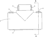
Fig. 5 is a kind of structural representation of connector shown in Figure 1 during from top view;
Fig. 6 is along the sectional structure schematic diagram of A-A line among Fig. 5;
Fig. 7 is second kind of structure of the utility model in a kind of perspective view that is in when being fastened and connected state;
Fig. 8 is a kind of perspective view of connector shown in Figure 7 when being in open mode;
Fig. 9 is embodiment 1 and a kind of structural representation after external bellows is connected;
Figure 10 is embodiment 2 and a kind of structural representation after external bellows is connected.
Be labeled as shown in the accompanying drawing: first connects semicanal material 1, the second connects semicanal material 2, and inwall 21 flexibly connects element 3, buckle assembly 4, buckle 41, the L type colludes pawl 411, guide plate 412, terminal 4121, draw-in groove 42, gathering sill 421, location hole 422, setting element 5, location-plate 51, terminal 511, location notch 52, head clamp 6, head clamp 61, head clamp 62, external bellows 8.
Embodiment
(embodiment 1)
Fig. 1 to Fig. 3 has shown a kind of embodiment of the present utility model, and wherein, Fig. 1 is first kind of structure of the utility model in a kind of perspective view that is in when being fastened and connected state; A kind of perspective view that Fig. 2 is a connector shown in Figure 1 when another angle is observed; Fig. 3 is a kind of perspective view of connector shown in Figure 1 when being in open mode; A kind of perspective view that Fig. 4 is a connector shown in Figure 3 when another angle is observed; Fig. 5 is a kind of structural representation of connector shown in Figure 1 during from top view; Fig. 6 is along the sectional structure schematic diagram of A-A line among Fig. 5.
Present embodiment is a kind of connector of being connected with bellows of being used for, and sees Fig. 1 to Fig. 6, comprises that first connects semicanal material 1 and be connected semicanal material 2 with second; The described first connection semicanal material 1 is connected semicanal material 2 with described second a side directly connects by flexibly connecting element 3, and described first connects semicanal material 1 is fastened and connected by buckle assembly 4 with described second another side that is connected semicanal material 2.
See Fig. 3, the described first connection semicanal material 1 is connected the semicanal material and is provided with setting element 5 by flexibly connecting element 3 direct-connected sides with described second; Described setting element 5 comprises and is arranged on first location-plate 51 that connects on the semicanal material 1, and is arranged on described second location notch 52 that is connected on the semicanal material 2, and the shape of described location lug and location notch 52 matches.The radial section shape of described location-plate 51 is camber line shapes, and the terminal 511 of location-plate 51 exceeds the inwall 21 of the described second connection semicanal material 2.
See Fig. 2 and Fig. 4, the described radial section shape that flexibly connects element 3 is a camber line shape, in the present embodiment, the described element 3 that flexibly connects is selected connecting plate for use, and the two ends of described connecting plate are separately positioned on the described first connection semicanal material 1 and are connected on the semicanal material 2 with described second; Described connecting plate is connected semicanal material 1 by injection molding and is connected semicanal material 2 part that becomes one with second with described first, and being able to be connected with described first semicanal material 1 and second, to be connected semicanal material 2 fixedly connected; Because this connecting plate can do it thinner when injection mo(u)lding, generally between 0.1 to 0.5mm, thereby make it become flexible piece.In concrete practice, also can by glued, weld and this connecting plate be connected semicanal material 1 and described second with described first to be connected semicanal material 2 fixedly connected.
Described buckle assembly 4 comprise be arranged on first connect on the semicanal material 1 buckle 41 be arranged on second draw-in groove 42 that is connected on the semicanal material 2; Described buckle 41 matches with the shape of described draw-in groove 42.Described buckle 41 comprises that the described first L type that connects on the semicanal material 1 that is fixedly installed on colludes pawl 411 and is fixedly installed on the guide plate 412 that described L type colludes pawl 411 outsides; Described draw-in groove 42 comprises gathering sill 421 and the location hole 422 that is arranged on the described second connection semicanal material 2, described gathering sill 421 matches with the guide part of a corresponding buckle 41, and described location hole 422 colludes pawl 411 with the L type of a corresponding buckle 41 and matches.The radial section shape of guide plate 412 is camber line shapes in the described buckle 41, and the terminal 4121 of guide plate 412 exceeds the inwall 21 of the described second connection semicanal material 2.
Described first connects semicanal material 1 is provided with the Semicircular head clamp 6 that cooperatively interacts with described second inwall 21 that is connected semicanal material 2; Described first connects semicanal material 1 is connected semicanal material 2 after being fastened and connected with described second, and the corresponding head clamp 62 that a head clamp 61 on the described first connection semicanal material 1 is connected with described second on the semicanal material 2 is enclosed ring-type.
In the present embodiment, described first connects semicanal material 1, and is connected the be fastened and connected shape of back composition of semicanal material 2 with second be the threeway shape.
(embodiment 2)
Fig. 7 and Fig. 8 show second kind of execution mode of the present utility model, and wherein Fig. 7 is second kind of structure of the utility model in a kind of perspective view that is in when being fastened and connected state; Fig. 8 is a kind of perspective view of connector shown in Figure 7 when being in open mode.
Present embodiment is substantially the same manner as Example 1, obstructed part is: described first connects semicanal material 1, and is connected the be fastened and connected three-way shape and the embodiment 1 of back composition of semicanal material 2 with second inequality, among the embodiment 1, first connects semicanal material 1 is connected the be fastened and connected left side opening of tee pipe coupling of back composition and the opening on the right of semicanal material 2 and is symmetrical arranged with second, its openings of sizes is identical; And in the present embodiment, the left side opening of the tee pipe coupling that the back that is fastened and connected is formed and the asymmetric setting of opening on the right, its opening is big on one side, and another side is less, is applicable to the external bellows of obstructed caliber to be connected.In addition, the osculum end of the tee pipe coupling that the back that is fastened and connected is formed is provided with two buckle assemblies.
In concrete practice, according to demand, can make described first connect semicanal material 1 is connected with second semicanal material 2 be fastened and connected shape that the back forms be two lead to, threeway, four-way or five-way shape.
The foregoing description 1 has beneficial technical effects with embodiment 2: (1) the various embodiments described above comprise that first is connected the semicanal material and is connected the semicanal material with second; The described first connection semicanal material is connected the semicanal material with described second a side directly connects by flexibly connecting element, and described first connects the semicanal material is fastened and connected by the buckle assembly with described second another side that is connected the semicanal material; This structure can be so that the various embodiments described above directly can be connected with external pipe by manner, thus have fitting operation comparatively simple, use advantage comparatively easily.
(2) in the various embodiments described above, the described element that flexibly connects is a connecting plate, and the two ends of described connecting plate are separately positioned on the described first connection semicanal material and are connected on the semicanal material with described second; Described connecting plate by glued, welding or; Especially make when being connected the semicanal material with described first and being connected the connecting plate that the semicanal material connects with second by injection molding, has bond strength preferably, if select suitable material again, for example select toughness nylon preferably for use, then also has extraordinary toughness, repeated multiple times is used, and also can not cause damage to connecting plate, and its useful life is very reliable, stable.
(3) in the various embodiments described above, described buckle assembly comprise be arranged on first connect on the semicanal material buckle be arranged on second draw-in groove that is connected on the semicanal material; Described buckle matches with the shape of described draw-in groove; Utilize buckle and draw-in groove, can easily the first connection semicanal material be connected the semicanal material with second and be fastened and connected.
(4) in the various embodiments described above, the radial section shape of guide plate is a camber line shape in the described buckle, and the terminal of guide plate exceeds the inwall of the described second connection semicanal material; Because the terminal of guide plate exceeds the inwall of the described second connection semicanal material, so the various embodiments described above are when being connected with external pipe, the terminal of guide plate can push against on the outer surface of external pipe, has the clamping external pipe, prevents the technique effect that it is loosening.
(5) in the various embodiments described above, the described first connection semicanal material is connected the semicanal material and is provided with setting element by flexibly connecting the direct-connected side of element with described second; Described setting element comprises and is arranged on first location-plate that connects on the semicanal material, and is arranged on described second location notch that is connected on the semicanal material, and the shape of described location lug and location notch matches; This setting element has assist location, auxiliary the two advantage according to suitable correct position cooperation when first connects semicanal material and described second and be connected the semicanal material and be fastened and connected.
(6) in the various embodiments described above, the radial section shape of described location-plate is a camber line shape, and the terminal of location-plate exceeds the inwall of the described second connection semicanal material; Because the terminal of location-plate exceeds the inwall of the described second connection semicanal material, so when being connected with external pipe, the terminal of location-plate can push against on the outer surface of external pipe, have the clamping external pipe, prevent the technique effect that it is loosening.
(7) in the various embodiments described above, described first connects the semicanal material is provided with the Semicircular head clamp that cooperatively interacts with described second inwall that is connected the semicanal material; Described first connects the semicanal material is connected the semicanal material after being fastened and connected with described second, and the corresponding head clamp that a head clamp on the described first connection semicanal material is connected on the semicanal material with described second is enclosed ring-type; This structure especially is fit to be fastened and connected with bellows, during use, only the draw-in groove on the bellows need be aimed at the head clamp in the various embodiments described above, directly fastening gets final product again, described head clamp is embedded in the draw-in groove of external bellows, thereby bellows is clamped in the tube chamber of the various embodiments described above.
(application examples)
Fig. 9 is embodiment 1 and a kind of structural representation after external bellows is connected, and Figure 10 is embodiment 2 and a kind of structural representation after external bellows is connected; Fig. 9 and Figure 10 have shown a kind of occupation mode of the present utility model.
In use, only the draw-in groove on the bellows 8 need be aimed at the head clamp 6 in the utility model, directly fastening gets final product again, and described head clamp 6 is embedded in the draw-in groove of external bellows 8, thereby bellows 8 is clamped in the tube chamber of the present utility model.
Obviously, the foregoing description of the present utility model only is for the utility model example clearly is described, and is not to be qualification to execution mode of the present utility model.For those of ordinary skill in the field, can also make other changes in different forms on the basis of the above description.Here need not also can't give exhaustive to all execution modes.And these belong to conspicuous variation or the change that spirit of the present utility model extended out and still are among the protection range of the present utility model.
Claims (10)
1, a kind of connector comprises that the first connection semicanal material (1) is connected semicanal material (2) with second; The described first connection semicanal material (1) is connected semicanal material (2) with described second a side directly connects by flexibly connecting element (3), and the described first connection semicanal material (1) is connected semicanal material (2) with described second another side is fastened and connected by buckle assembly (4).
2, connector according to claim 1 is characterized in that: described to flexibly connect element (3) be connecting plate, and the two ends of described connecting plate are separately positioned on described first and connect semicanal material (1) and be connected on the semicanal material (2) with described second; Described connecting plate passes through gluing, welding or is connected semicanal material (1) with described first by injection molding to be connected semicanal material (2) connection with second.
3, connector according to claim 2 is characterized in that: the described radial section shape that flexibly connects element (3) is a camber line shape.
4, connector according to claim 1 is characterized in that: described buckle assembly (4) comprise be arranged on first connect on the semicanal material (1) buckle (41) be arranged on second draw-in groove (42) that is connected on the semicanal material (2); Described buckle (41) matches with the shape of described draw-in groove (42).
5, connector according to claim 4 is characterized in that: described buckle (41) comprises that the described first L type that connects on the semicanal material (1) that is fixedly installed on colludes pawl (411) and is fixedly installed on the guide plate (412) that described L type colludes pawl (411) outside; Described draw-in groove (42) comprises gathering sill (421) and the location hole (422) that is arranged on the described second connection semicanal material (2), described gathering sill (421) matches with the guide part of a corresponding buckle (41), and described location hole (422) colludes pawl (411) with the L type of a corresponding buckle (41) and matches.
6, connector according to claim 5 is characterized in that: the radial section shape of guide plate (412) is a camber line shape in the described buckle (41), and the terminal (4121) of guide plate (412) exceeds the inwall (21) of the described second connection semicanal material (2).
7, connector according to claim 1 is characterized in that: the described first connection semicanal material (1) is connected the semicanal material and is provided with setting element (5) by flexibly connecting the direct-connected side of element (3) with described second; Described setting element (5) comprises and is arranged on first location-plate (51) that connects on the semicanal material (1), and is arranged on described second location notch (52) that is connected on the semicanal material (2), and the shape of described location lug and location notch (52) matches.
8, connector according to claim 7 is characterized in that: the radial section shape of described location-plate (51) is a camber line shape, and the terminal (511) of location-plate (51) exceeds the inwall (21) of the described second connection semicanal material (2).
9, connector according to claim 1 is characterized in that: the described first connection semicanal material (1) is connected semicanal material (2) with described second inwall (21) is provided with the Semicircular head clamp (6) that cooperatively interacts; Described first connects semicanal material (1) is connected semicanal material (2) after being fastened and connected with described second, and the corresponding head clamp (62) that the head clamp (61) on the described first connection semicanal material (1) is connected on the semicanal material (2) with described second is enclosed ring-type.
10, according to the described connector of one of claim 1 to 9, it is characterized in that: described first connect semicanal material (1) is connected with second semicanal material (2) be fastened and connected the shape of back composition be two lead to, threeway, four-way or five-way shape.
Priority Applications (1)
| Application Number | Priority Date | Filing Date | Title |
|---|---|---|---|
| CNU2008201344711U CN201243181Y (en) | 2008-08-20 | 2008-08-20 | Connector |
Applications Claiming Priority (1)
| Application Number | Priority Date | Filing Date | Title |
|---|---|---|---|
| CNU2008201344711U CN201243181Y (en) | 2008-08-20 | 2008-08-20 | Connector |
Publications (1)
| Publication Number | Publication Date |
|---|---|
| CN201243181Y true CN201243181Y (en) | 2009-05-20 |
Family
ID=40716475
Family Applications (1)
| Application Number | Title | Priority Date | Filing Date |
|---|---|---|---|
| CNU2008201344711U Expired - Fee Related CN201243181Y (en) | 2008-08-20 | 2008-08-20 | Connector |
Country Status (1)
| Country | Link |
|---|---|
| CN (1) | CN201243181Y (en) |
Cited By (5)
| Publication number | Priority date | Publication date | Assignee | Title |
|---|---|---|---|---|
| CN104466836A (en) * | 2015-01-03 | 2015-03-25 | 刘云标 | Self-locking type plastic spool tee joint |
| CN104466879A (en) * | 2014-11-14 | 2015-03-25 | 国网河南新安县供电公司 | Wire wiring tee-joint structure |
| CN108429183A (en) * | 2018-03-12 | 2018-08-21 | 广州南方电安科技有限公司 | A kind of cross arm insulator mask |
| CN110126294A (en) * | 2019-05-09 | 2019-08-16 | 常州信息职业技术学院 | Axial Assembled plastic inspection well well seat, forming processing device and processing method |
| WO2020133593A1 (en) * | 2018-12-28 | 2020-07-02 | 江苏英曼电子工业有限公司 | Pre-organized wire fastening device, electric plug connector adopting structure and female seat thereof |
-
2008
- 2008-08-20 CN CNU2008201344711U patent/CN201243181Y/en not_active Expired - Fee Related
Cited By (6)
| Publication number | Priority date | Publication date | Assignee | Title |
|---|---|---|---|---|
| CN104466879A (en) * | 2014-11-14 | 2015-03-25 | 国网河南新安县供电公司 | Wire wiring tee-joint structure |
| CN104466836A (en) * | 2015-01-03 | 2015-03-25 | 刘云标 | Self-locking type plastic spool tee joint |
| CN108429183A (en) * | 2018-03-12 | 2018-08-21 | 广州南方电安科技有限公司 | A kind of cross arm insulator mask |
| WO2020133593A1 (en) * | 2018-12-28 | 2020-07-02 | 江苏英曼电子工业有限公司 | Pre-organized wire fastening device, electric plug connector adopting structure and female seat thereof |
| US11502449B2 (en) | 2018-12-28 | 2022-11-15 | Jiangsu Enman Electronic Industry Co., Ltd. | Pre-organized wire fastening device, electric plug connector adopting structure and female seat thereof |
| CN110126294A (en) * | 2019-05-09 | 2019-08-16 | 常州信息职业技术学院 | Axial Assembled plastic inspection well well seat, forming processing device and processing method |
Similar Documents
| Publication | Publication Date | Title |
|---|---|---|
| CN201243181Y (en) | Connector | |
| CN104895052A (en) | Rapid joint of precast concrete pile | |
| CN206022664U (en) | A kind of adjustable power splicing tube | |
| CN102313109A (en) | Enhanced thermoplastic composite pipe buckling and pressing joint and buckling and pressing connection method | |
| CN202265942U (en) | Steel bar connector | |
| CN102313107A (en) | Wire rope enhanced thermoplastic composite pipe heating type buckling and pressing joint and connection method | |
| CN204728315U (en) | A kind of precast concrete pile snap joint | |
| CN206189745U (en) | Housing construction steel bar connection structure | |
| CN102979959A (en) | Pipe clamping component | |
| CN2864214Y (en) | Simple adapted big torque clutch | |
| CN202937911U (en) | Fast high-pressure pipe joint | |
| CN215329845U (en) | Precast concrete component and connecting piece thereof | |
| CN206320445U (en) | A kind of automobile brake hose joint | |
| CN207474690U (en) | A kind of tail folder connector for being suitble to a variety of cable specifications | |
| CN201764125U (en) | Stainless variable diameter straight tube | |
| CN201187120Y (en) | Reinforcing bar screwed connection sleeve | |
| CN105156781A (en) | Simple type thin-wall stainless steel pipe connection structure | |
| CN202809847U (en) | Quick connector for directly connecting steel pipes | |
| CN218385810U (en) | Saddle-shaped wire clamp | |
| CN220692402U (en) | Coupler conversion interface structure with good sealing performance | |
| CN219635131U (en) | Pipeline bundle support and vehicle | |
| CN218378248U (en) | Special-shaped tee joint for butt joint of automobile pipelines | |
| CN217301917U (en) | Novel antidetonation jib tube bank | |
| CN211401335U (en) | Flow meter centralized installation box for industrial measurement | |
| CN202914953U (en) | Saddle-shaped sample joint and interface device |
Legal Events
| Date | Code | Title | Description |
|---|---|---|---|
| C14 | Grant of patent or utility model | ||
| GR01 | Patent grant | ||
| C17 | Cessation of patent right | ||
| CF01 | Termination of patent right due to non-payment of annual fee |
Granted publication date: 20090520 Termination date: 20110820 |