CN201217618Y - Universal adjustable stay rod attachment apparatus of tower crane - Google Patents
Universal adjustable stay rod attachment apparatus of tower crane Download PDFInfo
- Publication number
- CN201217618Y CN201217618Y CNU2008200367970U CN200820036797U CN201217618Y CN 201217618 Y CN201217618 Y CN 201217618Y CN U2008200367970 U CNU2008200367970 U CN U2008200367970U CN 200820036797 U CN200820036797 U CN 200820036797U CN 201217618 Y CN201217618 Y CN 201217618Y
- Authority
- CN
- China
- Prior art keywords
- wall
- rod
- attached
- screw
- rods
- Prior art date
- Legal status (The legal status is an assumption and is not a legal conclusion. Google has not performed a legal analysis and makes no representation as to the accuracy of the status listed.)
- Expired - Fee Related
Links
Images




Landscapes
- Jib Cranes (AREA)
Abstract
本实用新型公开了起重机固定技术领域内的塔式起重机万能可调撑杆附着装置,包括附墙杆,附墙杆一端与墙体上的附墙环梁相连接,附墙杆另一端与塔体上的连接耳座相连接,附墙杆包括微调机构、杆件组件和连接座,连接座有两个并分别设置在附墙杆的两端位置,所述微调机构包括对称设置的两根丝杆,两根丝杆上的螺牙一正一反,两根丝杆上分别啮合有螺母,两螺母之间经套管相连接,一端的丝杆与连接座之一相连接,另一端的丝杆与一连接块相焊接,连接块上固定连接有两块相互平行的连接板;连接板与所述杆件组件的首端相对固定连接,杆件组件的末端与另一连接座相固定。其可将塔式起重机与墙体可靠固定,其连接强度高,使用安全、方便,能重复使用。

The utility model discloses a universal adjustable strut attachment device for a tower crane in the technical field of crane fixing, which comprises a wall-attached pole, one end of the attached wall pole is connected with a wall-attached ring beam on the wall, and the other end of the attached wall pole is connected with the tower The connecting ear seat on the body is connected. The wall-attached rod includes a fine-tuning mechanism, a rod component and a connecting seat. There are two connecting seats and are respectively arranged at the two ends of the wall-attached rod. The fine-tuning mechanism includes two Screw rod, the screw teeth on the two screw rods are positive and the other is reversed, the two screw rods are respectively engaged with nuts, the two nuts are connected through the sleeve, the screw rod at one end is connected with one of the connecting seats, and the other end The screw rod is welded with a connecting block, and two connecting plates parallel to each other are fixedly connected on the connecting block; the connecting plate is relatively fixedly connected with the head end of the rod component, and the end of the rod component is connected with another connecting seat fixed. The utility model can reliably fix the tower crane and the wall, has high connection strength, is safe and convenient to use, and can be used repeatedly.
Description
技术领域 technical field
本实用新型涉及一种起重机的固定装置,特别涉及用作塔式起重机的撑杆附着装置。The utility model relates to a fixing device of a crane, in particular to a strut attachment device used as a tower crane.
背景技术 Background technique
塔式起重机因其高度较高,在安装时,不仅要求其基础稳固,同时需要将塔体与所建筑的墙体用附着装置相连接,目前,公知的塔式起重机附着装置,一般包括有三到四根附墙杆,附墙杆一端经连接件与墙体上的附墙环梁相连接,附墙杆另一端经另一连接件与塔体上的连接耳座相连接,由于没有固定的附墙杆,目前附墙杆的形式多种多样,有厂家生产的,有工地自制的,有采用小口径钢管的,也有采用大口径钢管的,有采用方钢管的,还有采用型钢桁架式的,且附墙杆的长度唯一、不可调节。在实际的施工现场进行塔吊附着装置的安装过程中,需要根据实际施工距离将附墙杆进行切割、焊接。也就是实际附着距离大于现有的附墙杆的尺寸,则要将现有的附墙杆通过焊接一部分杆件进行接长,以满足实际使用的要求;如现有附墙杆长度大于实际附着距离时,则需要将多余的部分按照附着距离进行切割,以满足当前附着距离的需要。这样在实际的施工现场中进行工作,存在着三个方面的问题:一是延误施工周期,二是在施工现场没有相应的焊缝检查设备及忽略附墙杆的强度校核,安全隐患较大,三是浪费严重、成本增加。比如台州市建设规划局调研组发表的题为《0414号台风塔吊倒塌破坏原因分析及对策措施》(台州市建设规划局调研组)报告中指出:2004年14号台风中,有附墙杆焊缝脱焊4例,就是因附墙杆形式多样,造成本次塔吊倒塌事故的25%。Due to the high height of the tower crane, not only the foundation is required to be stable during installation, but also the tower body needs to be connected with the wall body of the building with an attachment device. At present, the known tower crane attachment devices generally include three to Four wall-attached poles, one end of the attached wall pole is connected with the wall-attached ring beam on the wall through a connecting piece, and the other end of the attached wall pole is connected with the connecting ear seat on the tower body through another connecting piece. There are various forms of wall-attached poles. Some are produced by manufacturers, some are self-made on site, some use small-diameter steel pipes, some use large-diameter steel pipes, some use square steel pipes, and some use steel trusses. Yes, and the length of the wall-attached rod is unique and cannot be adjusted. During the installation of the tower crane attachment device at the actual construction site, it is necessary to cut and weld the attached wall rod according to the actual construction distance. That is to say, the actual attachment distance is greater than the size of the existing wall-attached rod, and the existing wall-attached rod must be extended by welding a part of the rods to meet the requirements of actual use; if the length of the existing wall-attached rod is greater than the actual attachment When the distance is specified, the excess part needs to be cut according to the attachment distance to meet the needs of the current attachment distance. There are three problems in working on the actual construction site in this way: one is delaying the construction period, and the other is that there is no corresponding weld inspection equipment at the construction site and the strength check of the attached wall pole is neglected, and the safety hazard is relatively large. The third is serious waste and increased cost. For example, in the report titled "Cause Analysis and Countermeasures for the Collapse and Damage of Typhoon No. 0414 Tower Crane" (Research Team of Taizhou Construction Planning Bureau) published by the research team of Taizhou Construction Planning Bureau, it was pointed out that in Typhoon No. 14 in 2004, there were welding The 4 cases of seam de-welding are due to the various forms of the wall-attached poles, which caused 25% of the tower crane collapse accidents.
实用新型内容Utility model content
本实用新型提供一种塔式起重机万能可调附着装置,使其可克服现有的塔式起重机附墙杆生产形式、结构形式多样性,长度不可调节引起的施工现场进行切割、焊接延误施工进度、且又没有实际焊缝检验造成的安全隐患问题,实施附墙杆长度可调、施工中无需对附墙杆进行焊接、切割。The utility model provides a universal adjustable attachment device for a tower crane, which can overcome the existing production forms and structural forms of tower cranes attached to wall poles, and the length cannot be adjusted, which causes delays in construction progress due to cutting and welding at the construction site. , and there is no potential safety hazard caused by the actual weld inspection, the length of the attached wall pole is adjustable, and there is no need to weld or cut the attached wall pole during construction.
为实现上述目的,本实用新型的技术方案如下:塔式起重机万能可调撑杆附着装置,包括附墙杆,所述附墙杆一端与墙体上的附墙环梁相连接,附墙杆另一端与塔体上的连接耳座相连接,所述附墙杆包括微调机构、杆件组件和连接座,所述连接座有两个并分别设置在附墙杆的两端位置,所述微调机构包括对称设置的两根丝杆,两根丝杆上的螺牙一正一反,两根丝杆上分别啮合有螺母,两螺母上也设有与两根丝杆一一对应的正牙和反牙,两螺母之间经套管相连接,一端的丝杆与连接座之一相连接,另一端的丝杆与一连接块相焊接,所述连接块上固定连接有两块相互平行的连接板;连接板与所述杆件组件的首端相对固定连接,杆件组件的末端与另一连接座相固定。In order to achieve the above object, the technical scheme of the utility model is as follows: the attachment device for the universal adjustable strut of the tower crane includes a wall-attached pole, one end of the attached wall-attached pole is connected with the wall-attached ring beam on the wall, and the wall-attached pole The other end is connected with the connecting ear seat on the tower body. The wall-attached rod includes a fine-tuning mechanism, a rod assembly and a connecting seat. There are two connecting seats and they are respectively arranged at the two ends of the wall-attached rod. The fine-tuning mechanism includes two screw rods arranged symmetrically. The screw teeth on the two screw rods are positive and the other is reversed. Nuts are respectively engaged on the two screw rods. The two nuts are connected to each other through the casing, the screw rod at one end is connected to one of the connecting seats, and the screw rod at the other end is welded to a connecting block, and the connecting block is fixedly connected with two mutual Parallel connecting plates; the connecting plate is relatively fixedly connected to the head end of the rod component, and the end of the rod component is fixed to another connecting seat.
本实用新型通过同时转动两螺母,改变两根丝杆之间的间距,实现距离的调整,这样,在安装过程中,可以将一定长度的杆件组件安装定位在塔吊和墙体之间,其使用时,不需要进行焊接,通过杆件组件长度的调整,可达到塔吊的固定要求,杆件组件可制成标准件而被反复使用。本实用新型可对塔吊起更好的支撑、扶持作用,其安全隐患小,安装固定方便,杆件组件可实现标准化、模块化,与附墙耳座等组件配合使用后,不仅能满足实际附着距离变化需要,而且能保证各调节环节结构形式单一,焊接质量有保证,连接强度高,达到使用安全、方便、减少施工中的前期准备时间的使用效果,此外该装置能重复使用。The utility model changes the distance between the two screw rods by turning the two nuts at the same time to realize the adjustment of the distance. In this way, during the installation process, the rod assembly with a certain length can be installed and positioned between the tower crane and the wall. When in use, no welding is required, and the fixing requirements of the tower crane can be met by adjusting the length of the rod components, and the rod components can be made into standard parts and used repeatedly. The utility model can play a better role in supporting and supporting the tower crane. Its safety hazard is small, and it is convenient to install and fix. The rod components can realize standardization and modularization. The distance needs to be changed, and it can ensure that the structural form of each adjustment link is single, the welding quality is guaranteed, and the connection strength is high, so as to achieve the effect of safe and convenient use and reduce the preparation time in the early stage of construction. In addition, the device can be used repeatedly.
为保证附墙杆能够适应更大跨度的安装固定,所述杆件组件包括有顺序相连的这至少一根杆件,每一杆件均由H型钢制成,在H型钢的两侧槽口位置前后侧分别焊接有耳板,其中一端的耳板伸出端部外,另一端的耳板与端部平齐,杆件上的伸出端的耳板穿插至相邻杆件上平齐端的耳板之间或外侧,再由一对贯穿销使其相连接。杆件的长度可以不相等,这样,通过使用单根、双根或三根杆件,可组合出多组长度组合,现场施工时,可具有多种选择,可满足附着中心距离为3.5米-8米,附着跨距为6米-8米之间的任意组合。In order to ensure that the wall-attached rod can be adapted to the installation and fixing of a larger span, the rod assembly includes at least one rod connected in sequence, each rod is made of H-shaped steel, and the notches on both sides of the H-shaped steel Ear plates are welded on the front and rear sides of the position respectively. The ear plate at one end protrudes out of the end, and the ear plate at the other end is flush with the end. A pair of through pins are used to connect the ear plates between or on the outside. The length of the rods can be unequal. In this way, by using single, double or three rods, multiple sets of length combinations can be combined. During on-site construction, there are many options available, which can meet the attachment center distance of 3.5 meters -8 meters, and the attachment span is any combination between 6 meters and 8 meters.
为保证杆件组件和连接板之间能可靠连接,所述杆件组件首端设有初调机构,所述初调机构包括由H型钢构成的主体结构,在H型钢的首尾两端的两侧槽口位置分别焊接有幅板,两端的幅板轴向位置相错开,连接板穿插到其中一端的幅板两侧或之间,并由穿过两连接板和相应幅板的贯穿销相连接,另一端的幅板与相应杆件伸出端的耳板相穿插并经由贯穿销相连接。初调机构的H型钢构成的主体结构,具有强度大不易变形的优点,将杆件与连接板分别与初调机构相连,可保证相互之间具有足够大的连接强度。In order to ensure a reliable connection between the rod assembly and the connecting plate, an initial adjustment mechanism is provided at the head end of the rod assembly, and the initial adjustment mechanism includes a main structure composed of H-shaped steel, on both sides of the first and last ends of the H-shaped steel The positions of the notches are respectively welded with webs, the axial positions of the webs at both ends are staggered, and the connecting plate is inserted into the two sides or between the webs at one end, and connected by the through pins passing through the two connecting plates and the corresponding webs , the web plate at the other end is inserted into the lug plate at the protruding end of the corresponding rod and connected via a through pin. The main structure composed of H-shaped steel of the initial adjustment mechanism has the advantages of high strength and not easy to deform. Connecting the rods and connecting plates to the initial adjustment mechanism can ensure sufficient connection strength between them.
附图说明 Description of drawings
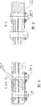
图1为本实用新型结构示意图。Fig. 1 is the structural representation of the utility model.
图2为微调机构结构示意图。Figure 2 is a schematic diagram of the structure of the fine-tuning mechanism.
图3为图1的A-A向视图。Fig. 3 is a view along the line A-A of Fig. 1 .
图4为初调机构的立体结构图。Fig. 4 is a three-dimensional structure diagram of the initial adjustment mechanism.
图5为初调机构的主视图。Figure 5 is a front view of the initial adjustment mechanism.
图6为初调机构的左视图。Figure 6 is a left view of the initial adjustment mechanism.
图7为初调机构的俯视图。Figure 7 is a top view of the initial adjustment mechanism.
图8为图1中的B-B或C-C向视图。Fig. 8 is a view from the direction of B-B or C-C in Fig. 1 .
图9为图1中的D-D向视图。Fig. 9 is a D-D arrow view in Fig. 1 .
图10杆件结构示意图。Figure 10 Schematic diagram of the rod structure.
图11为A-A断面处的又一种结构示意图。Fig. 11 is another structural schematic diagram at the section A-A.
图12为A-A断面处的第三种结构示意图。Fig. 12 is a schematic diagram of the third structure at the section A-A.
具体实施方式 Detailed ways
如图1-10,为塔式起重机万能可调撑杆附着装置,包括附墙杆,附墙杆一端与墙体上的附墙环梁1相连接,附墙杆另一端与塔体上的连接耳座8相连接,连接时采用连接销相连接,以便于拆卸;附墙杆由微调机构2、杆件组件和两个连接座7、9等部件组成,两个连接座7、9分别设置在附墙杆的两端位置,微调机构2包括对称设置的两根丝杆12、21,两根丝杆12、21上的螺牙一正一反,两根丝杆12、21上分别啮合有螺母10,两螺母10上也设有与两根丝杆12、21一一对应的正牙和反牙,螺母10为方形螺母,以便于转动,两螺母10之间经套管11相连接,套管11可遮蔽丝杆,避免灰尘进入螺纹部分,影响转动,一端的丝杆12与一个连接座9相连接,另一端的丝杆21与一连接块13相焊接,该连接块13上固定焊接有两块相互平行的连接板14,这样,可将连接块13、连接板14和丝杆21连接成一个整件;连接板14与所述杆件组件的首端相对固定连接,杆件组件的末端与另一连接座7相固定;该杆件组件由顺序相连的3根杆件组成,分别对应于图中的杆件4、杆件5、杆件6,每一杆件均由H型钢制成,在H型钢的两侧槽口位置前后侧分别焊接有耳板19、20,其中一端的耳板19伸出端部外,另一端的耳板20与H型钢的端部平齐,杆件上的伸出端的耳板19穿插至相邻杆件上平齐端的耳板20之间,也可以穿插至耳板20的外侧,再由一对贯穿销16使其相连接。所述杆件组件首端设有初调机构3,该初调机构3包括由H型钢构成的主体结构,在H型钢的首尾两端的两侧槽口位置分别焊接有幅板15、17,两端的幅板15、17轴向位置相错开,连接板14穿插到其中一端的幅板15两侧或之间,并由穿过两块连接板14和相应幅板15的贯穿销16相连接,另一端的幅板17与相应杆件伸出端的耳板19相穿插并经由贯穿销16相连接。As shown in Figure 1-10, it is a universal adjustable pole attachment device for tower cranes, including a wall pole, one end of the wall pole is connected with the
上述结构中,杆件4、5、6可构成一个杆件组件,各杆件的长度可以不相等,这样可以有更多的长度组合,可适应不同的现场情况而将塔吊良好固定,应当看到,杆件并不是局限于实施例中的三根,也可以是一根或两根,理论上讲,应当是至少一根,当只有一根杆件时,其无相邻杆件,杆件组件即为其本身。In the above structure, the
此外,初调机构也可以没有,如图11所示,可直接将伸出端耳板19与连接板相固定;在A-A断面位置,其连接方式也可以如图12所示,将初调机构3一端的幅板15、杆件伸出端的耳板19、连接板14相固定连接。In addition, the initial adjustment mechanism can also be absent, as shown in Figure 11, the
Claims (3)
Priority Applications (1)
| Application Number | Priority Date | Filing Date | Title |
|---|---|---|---|
| CNU2008200367970U CN201217618Y (en) | 2008-05-23 | 2008-05-23 | Universal adjustable stay rod attachment apparatus of tower crane |
Applications Claiming Priority (1)
| Application Number | Priority Date | Filing Date | Title |
|---|---|---|---|
| CNU2008200367970U CN201217618Y (en) | 2008-05-23 | 2008-05-23 | Universal adjustable stay rod attachment apparatus of tower crane |
Publications (1)
| Publication Number | Publication Date |
|---|---|
| CN201217618Y true CN201217618Y (en) | 2009-04-08 |
Family
ID=40540452
Family Applications (1)
| Application Number | Title | Priority Date | Filing Date |
|---|---|---|---|
| CNU2008200367970U Expired - Fee Related CN201217618Y (en) | 2008-05-23 | 2008-05-23 | Universal adjustable stay rod attachment apparatus of tower crane |
Country Status (1)
| Country | Link |
|---|---|
| CN (1) | CN201217618Y (en) |
Cited By (7)
| Publication number | Priority date | Publication date | Assignee | Title |
|---|---|---|---|---|
| CN103086287A (en) * | 2013-01-23 | 2013-05-08 | 唐山建设集团有限责任公司 | Modular combined-type tower crane attached bar with extensive stepless adjustment-type length |
| CN103848357A (en) * | 2014-03-17 | 2014-06-11 | 张亮 | Wall-attached device of tower crane |
| CN103979437A (en) * | 2014-05-26 | 2014-08-13 | 上海市机械施工集团有限公司 | Tower crane wall attached member bar device |
| CN104925680A (en) * | 2015-06-03 | 2015-09-23 | 中交第二航务工程局有限公司 | Method of stabilizing tower body of tower crane |
| CN105000481A (en) * | 2015-08-02 | 2015-10-28 | 周兆弟 | Tower crane with supporting rods |
| CN109292644A (en) * | 2018-10-12 | 2019-02-01 | 中国建筑第八工程局有限公司 | Energy-dissipating wall rod and its use method |
| CN114105016A (en) * | 2021-11-19 | 2022-03-01 | 徐州建机工程机械有限公司 | Stay bar combined type lower support |
-
2008
- 2008-05-23 CN CNU2008200367970U patent/CN201217618Y/en not_active Expired - Fee Related
Cited By (8)
| Publication number | Priority date | Publication date | Assignee | Title |
|---|---|---|---|---|
| CN103086287A (en) * | 2013-01-23 | 2013-05-08 | 唐山建设集团有限责任公司 | Modular combined-type tower crane attached bar with extensive stepless adjustment-type length |
| CN103848357A (en) * | 2014-03-17 | 2014-06-11 | 张亮 | Wall-attached device of tower crane |
| CN103979437A (en) * | 2014-05-26 | 2014-08-13 | 上海市机械施工集团有限公司 | Tower crane wall attached member bar device |
| CN104925680A (en) * | 2015-06-03 | 2015-09-23 | 中交第二航务工程局有限公司 | Method of stabilizing tower body of tower crane |
| CN105000481A (en) * | 2015-08-02 | 2015-10-28 | 周兆弟 | Tower crane with supporting rods |
| CN109292644A (en) * | 2018-10-12 | 2019-02-01 | 中国建筑第八工程局有限公司 | Energy-dissipating wall rod and its use method |
| CN109292644B (en) * | 2018-10-12 | 2024-11-12 | 中国建筑第八工程局有限公司 | Energy dissipation wall-attached rod and its use method |
| CN114105016A (en) * | 2021-11-19 | 2022-03-01 | 徐州建机工程机械有限公司 | Stay bar combined type lower support |
Similar Documents
| Publication | Publication Date | Title |
|---|---|---|
| CN201810323U (en) | Bolt connection plate for connecting tunnel inverted arch steel frame with arch angle steel frame | |
| CN106677505A (en) | Adjustable steel tube supporting piece and installation method thereof | |
| CN207633226U (en) | Easy-to-mount high stability supporting bridge fixed frame | |
| CN206418409U (en) | Assembled steel pipe holder for cast-in-place concrete construction of bridge | |
| CN220427381U (en) | Rotatable welding jig | |
| CN212705108U (en) | Auxiliary device for pipeline welding in narrow space | |
| CN201493642U (en) | Fixture for full welding of brake beam | |
| CN210369358U (en) | A fully bolted bolted ball grid support node | |
| CN203236172U (en) | Welded stud positioning device with good positioning effect | |
| CN204789118U (en) | Spot welding test block tear test tear device | |
| CN209830346U (en) | Positioning device for processing bicycle front fork | |
| CN112160606A (en) | Section bar lead screw combination reinforcing bar engineering construction equipment | |
| CN219298719U (en) | Adjustable hanging basket for welding H-shaped steel beam | |
| CN212153687U (en) | Assembled steel construction exempts from to pour concrete building structure | |
| CN203022174U (en) | Unit curtain wall switching connection adjusting device | |
| CN209817399U (en) | Assembled connecting device for steel pipe cross connection | |
| CN221030711U (en) | Round tube and H-shaped steel connection assembly type node | |
| CN223410539U (en) | A green building engineering frame beam reinforcement structure | |
| CN220698668U (en) | Assembly welding tool for inner door frame assembly of kitchen car | |
| CN207452898U (en) | A kind of clip pile device of municipal road construction vibratory piling machine | |
| CN206623083U (en) | A kind of Qu Wu robots for preventing that object from coming off | |
| CN222990897U (en) | Tool type anchor bolt assembly for fixing profile steel cantilever beam on building construction site | |
| CN220881226U (en) | A pipe joint device | |
| CN214459455U (en) | A movable pavement dowel rod fixing bracket | |
| CN222307777U (en) | Square equipment is upset frock for manufacturing |
Legal Events
| Date | Code | Title | Description |
|---|---|---|---|
| C14 | Grant of patent or utility model | ||
| GR01 | Patent grant | ||
| C17 | Cessation of patent right | ||
| CF01 | Termination of patent right due to non-payment of annual fee |
Granted publication date: 20090408 Termination date: 20100523 |