CN201202593Y - Magnetic suspension paddle distance self-adjusting vertical shaft wind power generator - Google Patents
Magnetic suspension paddle distance self-adjusting vertical shaft wind power generator Download PDFInfo
- Publication number
- CN201202593Y CN201202593Y CNU2008200245460U CN200820024546U CN201202593Y CN 201202593 Y CN201202593 Y CN 201202593Y CN U2008200245460 U CNU2008200245460 U CN U2008200245460U CN 200820024546 U CN200820024546 U CN 200820024546U CN 201202593 Y CN201202593 Y CN 201202593Y
- Authority
- CN
- China
- Prior art keywords
- generator
- shaft
- magnetic suspension
- impeller
- wind power
- Prior art date
- Legal status (The legal status is an assumption and is not a legal conclusion. Google has not performed a legal analysis and makes no representation as to the accuracy of the status listed.)
- Expired - Fee Related
Links
Images

Classifications
-
- Y—GENERAL TAGGING OF NEW TECHNOLOGICAL DEVELOPMENTS; GENERAL TAGGING OF CROSS-SECTIONAL TECHNOLOGIES SPANNING OVER SEVERAL SECTIONS OF THE IPC; TECHNICAL SUBJECTS COVERED BY FORMER USPC CROSS-REFERENCE ART COLLECTIONS [XRACs] AND DIGESTS
- Y02—TECHNOLOGIES OR APPLICATIONS FOR MITIGATION OR ADAPTATION AGAINST CLIMATE CHANGE
- Y02E—REDUCTION OF GREENHOUSE GAS [GHG] EMISSIONS, RELATED TO ENERGY GENERATION, TRANSMISSION OR DISTRIBUTION
- Y02E10/00—Energy generation through renewable energy sources
- Y02E10/70—Wind energy
- Y02E10/72—Wind turbines with rotation axis in wind direction
-
- Y—GENERAL TAGGING OF NEW TECHNOLOGICAL DEVELOPMENTS; GENERAL TAGGING OF CROSS-SECTIONAL TECHNOLOGIES SPANNING OVER SEVERAL SECTIONS OF THE IPC; TECHNICAL SUBJECTS COVERED BY FORMER USPC CROSS-REFERENCE ART COLLECTIONS [XRACs] AND DIGESTS
- Y02—TECHNOLOGIES OR APPLICATIONS FOR MITIGATION OR ADAPTATION AGAINST CLIMATE CHANGE
- Y02E—REDUCTION OF GREENHOUSE GAS [GHG] EMISSIONS, RELATED TO ENERGY GENERATION, TRANSMISSION OR DISTRIBUTION
- Y02E10/00—Energy generation through renewable energy sources
- Y02E10/70—Wind energy
- Y02E10/74—Wind turbines with rotation axis perpendicular to the wind direction
Abstract
The utility model discloses a magnetic suspension self-adjusting pitch vertical axis wind power generator, which comprises a magnetic suspension wind power generator; the generator shaft of the magnetic suspension wind power generator is integrally made with an impeller shaft of an impeller; the generator shaft is threaded into a motor shell; a generator rotor is arranged on the generator shaft; a generator stator is correspondingly arranged on the motor shell; at the same time, an axial magnetic suspension device and a radial magnetic suspension device are respectively arranged on the generator shaft and in the motor shell for magnetic suspension positioning; the impeller shaft is fixedly arranged in a wheel hub; and a plurality of blades of the impeller are connected with the wheel hub through a vertical axis self-adjusting pitch device. The utility model is simple in structure and easy to use and can effectively improve the overall performance and the efficiency of the wind power generator, which save energy sources and protect the environment and can be easily promoted.
Description
Technical field
The utility model relates to a kind of wind-driven generator, relates in particular to a kind of magnetic suspension paddle distance self-adjusting vertical shaft wind power generator.
Background technique
Wind-driven generator divides by the direction of running shaft, can be divided into two kinds of horizontal axis and vertical shaftes.Horizontal axis wind-driven generator is full-fledged in theory at properller, is widely used at present.But manufacturing and designing of horizontal axis wind-driven generator is all very complicated, has: 1. impeller takes up space big with floor space; 2. the wind tower is had relatively high expectations; 3. shortcoming such as the impeller wind-engaging is inhomogeneous, the blade of unsettled installation particularly, also to bear the huge positive pressure of wind, thereby its cost is very high, single-machine capacity is big more, its cost is big more, and this is that the wind-powered electricity generation price is higher than one of principal element of civil power so far, and vertical axis aerogenerator has more advantage by contrast.
Traditional vertical axis aerogenerator all is provided with a blade turning mechanism, makes mechanism complicated, and cost improves, and has also consumed the energy of wind greatly.And this wind-driven generator can not self-starting, and additional starting mechanism has increased the weight of manufacture cost again, thereby causes power coefficient to be had a greatly reduced quality, and the superiority of vertical axis aerogenerator is also just all gone.
In order effectively to utilize wind energy, traditional vertical axis aerogenerator is made the blade of feather, but its defective is to adjust the pusher structure of attack angle of blade, has both too much consumed energy, has caused wind energy conversion system not start voluntarily again.The someone finds that the blade of hinge can swing in rotation in recent years, so the restriction nail just occurred blade oscillating is limited in the reasonable angle of attack.But restricted nail just has bump, is easy to damage in long-term, cycle and strong impaction lower blade.
At present, what employing parallel connecting rod type vertical axis aerogenerator was maximum is Japan's (beginning one's study in 2002), also have states such as Britain, Canada at present also in development, most of product of these countries adopts parallel connecting rod in the middle of impeller design, this mode is had relatively high expectations to the generator output shaft, and the structure relative complex, on-the-spot installation procedure is also on the high side.In addition, from the terms of mechanics analysis, H type vertical axis aerogenerator power is big more, blade is long more, the central point of parallel bar is long more with the central point distance of sending out generator shaft, and wind loading rating is just poor more.Traditional vertical axis aerogenerator will overcome the deadweight and the frictional force of driving mechanism simultaneously, also will overcome simultaneously because the resistance that generator amature deadweight and mechanical bearing friction bring makes the driving force of transmission drive system increase, and has reduced generator efficiency.
Therefore, raise the efficiency in order to improve the overall performance of wind-driven generator, to reach, energy-conservation, consumption reduction, environmental protection and the purpose easily popularized, must traditional vertical axis aerogenerator system be transformed.
The model utility content
The purpose of this utility model is exactly in order to address the above problem, provide a kind of have simple in structure, easy to use, can effectively improve the overall performance of wind-driven generator, raise the efficiency, energy-conservation, consumption reduction, environmental protection and the magnetic suspension paddle distance self-adjusting vertical shaft wind power generator of advantage such as easily popularize.
For achieving the above object, the utility model adopts following technological scheme:
A kind of magnetic suspension paddle distance self-adjusting vertical shaft wind power generator, it comprises magnetic suspending wind turbine generator, the generator shaft of magnetic suspending wind turbine generator and the impeller shaft of impeller are made into integration, generator shaft penetrates in the electric machine casing, generator amature is installed on generator shaft, Dui Ying electric machine casing is provided with generator unit stator with it, goes back installation shaft to magnetic levitation system and axial magnetic device on generator shaft and in the electric machine casing simultaneously, carries out the magnetic suspension location; Impeller shaft is fixedly mounted in the wheel hub, and several blade pass of impeller are crossed vertical shaft paddle distance self-adjusting device and linked to each other with wheel hub.
Described axial magnetic suspension device comprises the fixed tray that is arranged on the electric machine casing inner tip, and fixed tray and generator shaft connect firmly, and is provided with the axial upper magnet of at least one annular on fixed tray, and Dui Ying electric machine casing is provided with corresponding axially lower magnet with it.
Described axial magnetic device comprises at least one internal magnet radially that is arranged on the generator shaft, and Dui Ying electric machine casing is provided with accordingly radially outer magnet with it.
Described vertical shaft paddle distance self-adjusting device comprises a pair of connecting rod, and they and wheel hub connect firmly, and the connecting rod the other end is connected with vertical vertical rod, three's triangularity structure, and blade is then hinged by hinge and vertical rod, realizes paddle distance self-adjusting.
The utility model has removed traditional mechanical bearing and has adopted magnetic levitation system between the generator shaft of generator and electric machine casing; this structure is playing the purpose that reduces friction driving greatly on the one hand aspect the power transmission of vertical axis aerogenerator; also overcome substantially on the other hand because the driving force consumption that deadweight brought of wind energy conversion system weight and generator self rotor; owing to be full the suspension; frictional force is little; realized starting voluntarily after this machine is shut down, the superiority of vertical axis windmill has represented to come out comprehensively fully.
Impeller shaft is made of one with a generator shaft, located by magnetic suspension, wind-driven generator axially by permanent magnetism magnetic suspension thrust-balancing bearings, axially going up magnet is a ring magnet, is fixed on the fixed tray, and is fixed on the generator shaft by fixed tray, rotate with generator shaft, axially lower magnet is fixed on the electric machine casing, and last lower magnet interacts by repulsion, has overcome substantially because the driving force consumption that deadweight brought of wind energy conversion system weight and generator self rotor.
Wind-driven generator is radially done circumferential registration by the magnetic suspension positioning device, and radially internal magnet is an annular, is fixed on the generator shaft, and radially external magnet is an annular also, is fixed on the electric machine casing, by repulsion and radially internal magnet interaction.Friction factor is almost nil between the rotating part of wind-driven generator and the localization part like this, compares transmission efficiency with similar traditional wind and is significantly improved.Simultaneously impeller can not only transmit than high pulling torque and give generator, but also can eliminate mechanical vibration, reduces voice, can lubricate and works stably in a long term.Do not need to lubricate, can simplify blower fan structure, exempt daily maintaining, can long-term stability work reliably, simultaneously because the running resistance of magnetic bearing is zero, so this also is a kind of energy-efficient blower fan.
In order effectively to utilize wind energy, traditional vertical axis aerogenerator is made the blade of feather, but its defective is to adjust the pusher structure of attack angle of blade, has both too much consumed energy, has caused wind energy conversion system not start voluntarily again.Vertical axis aerogenerator of the present utility model mostly adopts the parallel connecting rod structure in the middle of impeller design, this mode is had relatively high expectations to the generator output shaft, and the structure relative complex, and on-the-spot installation procedure is also on the high side.In addition, from the terms of mechanics analysis, H type vertical axis aerogenerator power is big more, blade is long more, the central point of parallel bar is long more with the central point distance of sending out generator shaft, and wind loading rating is just poor more.
Common vertical axis aerogenerator can't ensure between blade and air-flow to keep optimum contact angle, and there is complex structure in pitch control system, the cost height, and wind energy consumption is big, can't be to defectives such as large scale developments.
Blade pass of the present utility model is crossed hinge and is linked to each other with vertical rod, and blade can freely rotate around vertical rod, and each vertical rod is fixed on the wheel hub by two connecting rods, and wheel hub and impeller shaft are fixed together, and impeller shaft directly drives generator for electricity generation.Vertical rod and two connecting rods constitute triangle.
Owing to adopted special air principle of dynamics, the Placement of triangle vector method and the principle of directly driving type structure, make the stressed of impeller mainly concentrate on the wheel hub, therefore wind loading rating is stronger, adopts the diagonal brace of triangle vector method can significantly reduce the unsettled size of blade.
Compare with horizontal axis wind-driven generator and traditional vertical axis aerogenerator, the blade of magnetic suspension vertical shaft wind-driven generator of the present utility model is hinged with wheel arm one end, realize blade automatic pitch established angle of adjusting in wheel rotation, do not need complicated adjusting mechanism just can reach the designing requirement at the best angle that facings the wind, and simple in structure, efficient is high, cost is low.Blade remains the best angle that facings the wind, and produces maximum thrust, improves generating efficiency.When wind direction was relatively stable, impeller rotated a circle, and blade is done cyclically-varying, and when blade is in positive down wind or during against the wind to 2, the angle that facings the wind is zero, other any positions have all down with the wind that the angle produces, thereby all have thrust to produce.
When wind during to static wind-driven generator, on one side blade mutually suitable with wind direction, blade is vertical with wind direction on one side, has so just formed a resistance difference formula wind energy conversion system, gets up immediately under the wind-force effect, finishes startup voluntarily.Instantaneous what start, pneumatic equipment blades made is adjusted into the best angle of attack automatically, enters the lift-type machine and runs well.This process is fully automatically, and does not have any additional device and additionaling power.
Every use a period of time of blade of the present utility model, blade can be disassembled and keep in repair, perhaps directly change standby blade, blade can be complete make the different spare parts of size, difference according to the wind resource situation, use the blade of different size, this point is the unique distinction that other any wind energy conversion system does not possess.The beneficial effects of the utility model are: adopt specific magnetic structure, provide a kind of and utilize magnetic levitation technology to reduce wind-force to send out the frictional force that generator axial force and radial force cause.Starting resistance square, starting wind velocity, the incision wind speed of wind-driven generator can be effectively reduced, output power can be improved by a relatively large margin simultaneously.
Description of drawings
Fig. 1 is a wind-driven generator structure schematic representation of the present utility model;
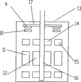
Fig. 2 is a generator magnetic levitation system structural representation.
Wherein, 1. impeller, 2. impeller shaft, 3. connecting rod, 4. wheel hub, 5. vertical rod, 6. blade, 7. generator, 8. pylon, 9. axially go up magnet, 10. axial lower magnet, 11. generator unit stators, 12. generator amature, 13. electric machine casings, 14. inner magnets radially, 15. external magnet radially, 16. generator shafts, 17. fixed trays.
Embodiment
Below in conjunction with accompanying drawing and embodiment the utility model is described further.
Among Fig. 1, the generator shaft 16 of magnetic suspending wind turbine generator is made into integration with the impeller shaft 2 of impeller 1, generator shaft 16 penetrates in the electric machine casing 13, generator amature 12 is installed on generator shaft 16, Dui Ying electric machine casing 13 is provided with generator unit stator 11 with it, and impeller 1 comprises a plurality of blades 6, and each blade 6 is connected with vertical vertical rod 5 by hinge, vertical rod 5 is connected three's triangularity with two connecting rods 3; Two connecting rods 3 are fixed on the wheel hub 4, and wheel hub 4 connects firmly with impeller shaft 2, and drives its rotation.Generator 7 is installed on the pylon 8.
Among Fig. 2, generator 7 comprises electric machine casing 13, is provided with fixed tray 17 in electric machine casing 13 inner tip, and it and generator shaft 16 connect firmly, and fixed tray 17 is provided with the axial magnet 9 of going up of annular, and Dui Ying electric machine casing 13 is provided with the axial lower magnet 10 of annular with it.Upper and lower at generator amature 12 respectively is provided with a radially internal magnet 14, then is provided with radially external magnet 15 on the Dui Ying electric machine casing 13 with it.
Claims (4)
1. magnetic suspension paddle distance self-adjusting vertical shaft wind power generator, it is characterized in that, it comprises magnetic suspending wind turbine generator, the generator shaft of magnetic suspending wind turbine generator and the impeller shaft of impeller are made into integration, generator shaft penetrates in the electric machine casing, and generator amature is installed on generator shaft, and Dui Ying electric machine casing is provided with generator unit stator with it, go back installation shaft to magnetic levitation system and axial magnetic device on generator shaft and in the electric machine casing simultaneously, carry out the magnetic suspension location; Impeller shaft is fixedly mounted in the wheel hub, and several blade pass of impeller are crossed vertical shaft paddle distance self-adjusting device and linked to each other with wheel hub.
2. magnetic suspension paddle distance self-adjusting vertical shaft wind power generator as claimed in claim 1, it is characterized in that, described axial magnetic suspension device comprises the fixed tray that is arranged on the electric machine casing inner tip, fixed tray and generator shaft connect firmly, be provided with the axial upper magnet of at least one annular on fixed tray, Dui Ying electric machine casing is provided with corresponding axially lower magnet with it.
3. magnetic suspension paddle distance self-adjusting vertical shaft wind power generator as claimed in claim 1, it is characterized in that, described axial magnetic device comprises at least one internal magnet radially that is arranged on the generator shaft, and Dui Ying electric machine casing is provided with accordingly radially outer magnet with it.
4. magnetic suspension paddle distance self-adjusting vertical shaft wind power generator as claimed in claim 1, it is characterized in that, described vertical shaft paddle distance self-adjusting device comprises a pair of connecting rod, they and wheel hub connect firmly, the connecting rod the other end is connected with vertical vertical rod, three's triangularity structure, blade are then hinged by hinge and vertical rod, realize paddle distance self-adjusting.
Priority Applications (1)
| Application Number | Priority Date | Filing Date | Title |
|---|---|---|---|
| CNU2008200245460U CN201202593Y (en) | 2008-06-24 | 2008-06-24 | Magnetic suspension paddle distance self-adjusting vertical shaft wind power generator |
Applications Claiming Priority (1)
| Application Number | Priority Date | Filing Date | Title |
|---|---|---|---|
| CNU2008200245460U CN201202593Y (en) | 2008-06-24 | 2008-06-24 | Magnetic suspension paddle distance self-adjusting vertical shaft wind power generator |
Publications (1)
| Publication Number | Publication Date |
|---|---|
| CN201202593Y true CN201202593Y (en) | 2009-03-04 |
Family
ID=40424907
Family Applications (1)
| Application Number | Title | Priority Date | Filing Date |
|---|---|---|---|
| CNU2008200245460U Expired - Fee Related CN201202593Y (en) | 2008-06-24 | 2008-06-24 | Magnetic suspension paddle distance self-adjusting vertical shaft wind power generator |
Country Status (1)
| Country | Link |
|---|---|
| CN (1) | CN201202593Y (en) |
Cited By (5)
| Publication number | Priority date | Publication date | Assignee | Title |
|---|---|---|---|---|
| CN101873030A (en) * | 2010-06-04 | 2010-10-27 | 江苏星马力科技有限公司 | Permanent magnet suspension impeller blower |
| WO2011094914A1 (en) * | 2010-02-08 | 2011-08-11 | 国能风力发电有限公司 | Magnetic suspension support device for vertical shaft wind-driven generator |
| CN102392789A (en) * | 2011-07-28 | 2012-03-28 | 深圳市耐沃克科技有限公司 | Counter-rotating double-blade fully permanent-magnet suspended vertical axis wind turbine |
| CN105553176A (en) * | 2016-01-12 | 2016-05-04 | 张大鹏 | Magnetic levitation device for vertical-axis wind turbine |
| CN110080940A (en) * | 2019-04-10 | 2019-08-02 | 卞云 | A kind of wind-driven generator |
-
2008
- 2008-06-24 CN CNU2008200245460U patent/CN201202593Y/en not_active Expired - Fee Related
Cited By (8)
| Publication number | Priority date | Publication date | Assignee | Title |
|---|---|---|---|---|
| WO2011094914A1 (en) * | 2010-02-08 | 2011-08-11 | 国能风力发电有限公司 | Magnetic suspension support device for vertical shaft wind-driven generator |
| CN101873030A (en) * | 2010-06-04 | 2010-10-27 | 江苏星马力科技有限公司 | Permanent magnet suspension impeller blower |
| CN102392789A (en) * | 2011-07-28 | 2012-03-28 | 深圳市耐沃克科技有限公司 | Counter-rotating double-blade fully permanent-magnet suspended vertical axis wind turbine |
| CN105553176A (en) * | 2016-01-12 | 2016-05-04 | 张大鹏 | Magnetic levitation device for vertical-axis wind turbine |
| WO2017120704A1 (en) * | 2016-01-12 | 2017-07-20 | 张大鹏 | Magnetic levitation device for vertical-axis wind power generator |
| CN105553176B (en) * | 2016-01-12 | 2018-07-17 | 张大鹏 | The magnetic levitation system of vertical axis aerogenerator |
| CN110080940A (en) * | 2019-04-10 | 2019-08-02 | 卞云 | A kind of wind-driven generator |
| CN110080940B (en) * | 2019-04-10 | 2021-09-14 | 吉电(滁州)章广风力发电有限公司 | Wind-driven generator |
Similar Documents
| Publication | Publication Date | Title |
|---|---|---|
| CN101302997B (en) | Magnetic suspension paddle distance self-adjusting vertical shaft wind power generator | |
| WO2016173304A1 (en) | Novel wind turbine linkage variable pitch system | |
| CN105840430A (en) | Small vertical shaft magnetic suspension wind driven generator | |
| CN101915214A (en) | Five-freedom degree full-suspension vertical shaft wind power generator in outer-rotor structure | |
| CN102926939A (en) | Five-freedom full suspension vertical shaft disc type wind-driven generator | |
| CN201202593Y (en) | Magnetic suspension paddle distance self-adjusting vertical shaft wind power generator | |
| CN101949360A (en) | Co-rotating double-blade vertical wind driven generator | |
| CN201515291U (en) | Direct-drive wind generator | |
| CN102364094A (en) | Bidirectional wind barrel type magnetic suspension wind power generation device | |
| CN202326021U (en) | Two-way air duct type magnetic suspension wind power generation device | |
| CN103133264B (en) | Wind driven generator system based on flywheel energy storage speed adjustment | |
| CN102182624A (en) | Magnetic suspension horizontal shaft direct-driving type wind driven generator with five freedom degrees | |
| CN201730753U (en) | Five-degree-of-freedom full-suspension vertical-axis wind driven generator with outer rotor structure | |
| CN2767696Y (en) | Double-rotor wind-driven generator | |
| CN101943132A (en) | Mutually-inversely-rotated double-wind-blade magnetically-suspended vertical wind power generator | |
| CN204226104U (en) | Small-sized hybrid vertical axis wind energy collecting device | |
| CN103967701A (en) | Lift-drag complementary type vertical axis breeze wind turbine | |
| CN202937410U (en) | Five-degree-of-freedom full-suspension vertical shaft disc type wind driven generator | |
| JP5832139B2 (en) | Wind power generator | |
| CN2777234Y (en) | Magnetic suspension vertical axis directly-driven variable-speed constant frenquency type wind-power electric generator | |
| CN211258886U (en) | Wind power generator | |
| CN103726991B (en) | Planetary speedup wind wheel vertical-shaft aerogenerator | |
| CN203412700U (en) | Vertical shaft wind driven generator | |
| CN202023698U (en) | Novel unassisted variable-pitch wind driven generator | |
| CN205089529U (en) | Horizontal shaft magnetic suspension wind driven generator |
Legal Events
| Date | Code | Title | Description |
|---|---|---|---|
| C14 | Grant of patent or utility model | ||
| GR01 | Patent grant | ||
| C17 | Cessation of patent right | ||
| CF01 | Termination of patent right due to non-payment of annual fee |
Granted publication date: 20090304 Termination date: 20100624 |