CN201186323Y - Discrete mold for stretch-bending form - Google Patents
Discrete mold for stretch-bending form Download PDFInfo
- Publication number
- CN201186323Y CN201186323Y CNU2008200283759U CN200820028375U CN201186323Y CN 201186323 Y CN201186323 Y CN 201186323Y CN U2008200283759 U CNU2008200283759 U CN U2008200283759U CN 200820028375 U CN200820028375 U CN 200820028375U CN 201186323 Y CN201186323 Y CN 201186323Y
- Authority
- CN
- China
- Prior art keywords
- mould
- element body
- connecting bolt
- fixture block
- stretch
- Prior art date
- Legal status (The legal status is an assumption and is not a legal conclusion. Google has not performed a legal analysis and makes no representation as to the accuracy of the status listed.)
- Expired - Lifetime
Links
Images


Abstract
The utility model relates to a discrete die which is used in stretch bending forming and comprises basic objects (5), a cushion layer (4), a connecting bolt (7) and two fixture blocks (6). The end surfaces of one ends of the basic objects (5) are arc working surfaces (10) and a through hole (11) which is matched with the connecting bolt (7) is arranged in the middle portion. One fixture block, a plurality of basic objects and one fixture block are installed on the connecting bolt (7) in turn and are clamped and fixed to integrate a die, and the position of each basic object working surface (10) is adjusted through adjusting the position (11) that the connecting bolt is threaded through a continuous groove on each basic object. The die is fixed on a working table of a stretch bender through a mounting hole (9) to bend and form workpieces (2) which need forming. In the forming process, an external form surface shape of the die is changed through finely adjusting the positions of the basic objects (5) to compensate the influence of resilience to the forming precision, the discrete die can adapt the resilience control demands of different stretch bending parts and has the characteristics of simple structure, convenient use, high production efficiency and low cost.
Description
One, technical field
The present invention relates to field of machining, specifically is a kind of discrete mould that is used for stretch wrap forming.
Two, background technology
It is big that stretch bending process is used for manufacturing dimension, and the profile accuracy requirement is higher, and the curved material bool of extruding that relative bending radius is big and plate is the important production technology of making constitutional details such as frame on car, ship, the aircraft, rib, edge strip.
As shown in Figure 1, for a long time, rigid unitary stretch bending mould 1 is all adopted in the manufacturing of stretch bending part, and workpiece 2 is placed on the rigid unitary stretch bending mould 1, and two ends apply pulling force by chuck 3 to workpiece, make its shaping.This manufacturing process rebound phenomenon can occur because of unloading back stretch bending workpiece 2, in order to control resilience, need repair a die repeatedly, carries out technological experiment repeatedly, waste time and energy, and precision is difficult to guarantee.Simultaneously, workpiece of this method promptly needs a mould, causes number of molds huge, has increased production cost.
Three, summary of the invention
A part needs a mould in the existing stretch bending technology in order to overcome, and number of molds is huge in causing producing, and production cost height, and the component shaping precision deficiency that is difficult to guarantee the present invention proposes a kind of discrete mould that is used for stretch wrap forming.
The present invention is integrated into the mould with certain profile with a plurality of discrete element bodies, and this mould can make up arbitrarily according to the requirement of formed thereby section bar, comprises a plurality of element bodies, bed course, two fixture blocks, connecting bolt.Wherein, element body is the elementary cell of mould, is cuboid, and width is greater than the width of workpiece to be formed, and the end face of an end is a working face, and this working face is a cambered surface; There is the strip through-hole that cooperates with connecting bolt at the middle part of element body; The quantity of element body is determined according to the span size and the element body thickness of institute's processing parts.
Adopt elastomeric material in order to the bed course of eliminating the gap of each element body in integrated, this bed course should have enough elastic deformabilities and certain rigidity, is placed on walk-off-mode element body working face surface.
Fixture block is " L " shape, its with vertical plane that the walk-off-mode element body contacts on two through holes that are used to install connecting bolt are arranged.The horizontal plane of fixture block has two to be used for and the fixing installing hole of stretch benders work top on base as base.
When assembly jig, successively a fixture block, a plurality of element body, a fixture block string are contained on the connecting bolt, and are fixedly clamped, be integrated into mould; Be placed in the mating surface of elastic insert and each element body that forms mould on the mould, promptly the external envelope face is the work profile of mould; Adjust the position of each element body working face by adjusting position that connecting bolt passes the through hole on each element body, make its external envelope face satisfy required work profile shape.After assembling walk-off-mode, by being positioned at two installation through holes on the fixture block, walk-off-mode is fixed on the workbench of stretch benders, and elastic insert is overlayed on the outer mold surface of discrete element body, place the section bar workpiece for the treatment of stretch bending at last, carry out stretch wrap forming.
The present invention is integrated into the mould that adapts according to the requirement of Forming Workpiece profile with a plurality of discrete element bodies, utilizes general stretch benders that section bar is carried out stretch wrap forming; In the forming process,, change the outer mold surface shape of walk-off-mode,, realize the Accurate Shaping of stretch bending part with the influence of compensation resilience to forming accuracy by the position of fine setting element body.The present invention replaces traditional whole stretch wrap forming mould with stretch bending mould that can be integrated, its work profile is easy to adjust, can adapt to the needs of different stretch bending part resilience controls, reduces manufacturing and designing the cycle of stretch bending part significantly, improve the manufacturing efficient of stretch bending part, reduced production cost.
Fig. 1 is traditional stretch wrap forming principle schematic.Rigid unitary stretch bending mould 1 is fixed on the stretch benders workbench among the figure, by chuck 3 stretch bending power 4 is applied on the curved workpieces 2.
Fig. 2 is a structural representation front view of the present invention.
Fig. 3 is a structural representation vertical view of the present invention.
Fig. 4 is a structural representation side view of the present invention.
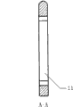
Fig. 5 is the front view of element body.
Fig. 6 is the A-A cutaway view of element body.
Fig. 7 is the front view of fixture block.
Fig. 8 is the side view of fixture block.Wherein:
1. whole stretch bending mould 2. workpiece 3. chucks 4. bed courses 5. element bodies
6. fixture block 7. bolts 8. external envelope faces 9. fixture block through holes 10. element body working faces
11. element body through hole 12. installing holes
Five, the specific embodiment
Embodiment one
Present embodiment is to be used for the rectangle that the forming profiles part section is 15*20mm, radius is 350mm, length is the stretch bending mould of the arc profile part of 510mm, it is characterized in that a plurality of discrete element bodies are integrated into the mould with certain profile, and this mould can make up arbitrarily according to the requirement of formed thereby section bar.This mould comprises element body 5, bed course 4, two fixture blocks 6, bolt 7.
In the present embodiment, element body is the elementary cell of mould, is integrated into mould by 13 element bodies.The lotus size that the appearance and size of element body is carried according to stretch bending reaches to be determined the requirement of mold stiffness.Be convenient processing and use, the work cambered surface of the element body of present embodiment is got arc surface, and the diameter of this circular arc equates with element body thickness.Element body 5 is a cuboid, and its cross section is a rectangle, and thickness is 15mm, and width is greater than workpiece to be formed, and there is the strip through-hole 11 that matches with connecting bolt 7 centre.
During assembly jig, at first two fastening bolts 7 are passed the through hole 12 of a fixture block 6, each element body 5 strings that then centre had through hole 11 are installed another fixture block 6 then on bolt 7, and fixing by connecting bolt 7.Before being fastenedly connected bolt 7, according to the measurement frock or the profile clamp of section bar, adjust the position of each element body 5, make its external envelope face 8, promptly the inner surface of bed course reaches required work profile shape.After assembling mould, by being positioned at two installation through holes 9 on the fixture block 6, mould is fixed on the workbench of stretch benders, and elastic insert 4 is overlayed on the outer mold surface of the element body after integrated, place the section bar workpiece 2 for the treatment of stretch bending at last, carry out stretch wrap forming.
Embodiment two
Present embodiment is to be used for the rectangle that the forming profiles part section is 150*200mm, radius is 3000mm, length is the stretch bending mould of the arc profile part of 3140mm, it is characterized in that a plurality of discrete element bodies are integrated into the mould with certain profile, and this mould can make up arbitrarily according to the requirement of formed thereby section bar.This mould comprises element body 5, bed course 4, two fixture blocks 6, bolt 7.
In the present embodiment, element body is the elementary cell of mould, is integrated into mould by 20 element bodies.The lotus size that the appearance and size of element body is carried according to stretch bending reaches to be determined the requirement of mold stiffness.The work cambered surface of element body is got oval cambered surface, and the length ratio of minor axis and major axis should be between 0.2-1.The long axis of ellipse diameter of present embodiment equates that with element body thickness minor axis length is half of major axis.Element body 5 is a cuboid, and its cross section is a rectangle, and thickness is 150mm, and width is greater than workpiece to be formed, and there is the strip through-hole 11 that matches with connecting bolt 7 centre.
During assembly jig, at first two fastening bolts 7 are passed the through hole 12 of a fixture block 6, each element body 5 strings that then centre had through hole 11 are installed another fixture block 6 then on bolt 7, and fixing by connecting bolt 7.Before being fastenedly connected bolt 7, according to the measurement frock or the profile clamp of section bar, adjust the position of each element body 5, make its external envelope face 8, promptly the inner surface of bed course reaches required work profile shape.After assembling mould, by being positioned at two installation through holes 9 on the fixture block 6, mould is fixed on the workbench of stretch benders, and elastic insert 4 is overlayed on the outer mold surface of the element body after integrated, place the section bar workpiece 2 for the treatment of stretch bending at last, carry out stretch wrap forming.
Claims (3)
1. a discrete mould that is used for stretch wrap forming is characterized in that also comprising elastic insert (4), connecting bolt (7) and two fixture blocks (6), wherein:
A. mould is by connecting bolt (7) and integrated the forming of fixture block (6) by a plurality of element bodies (5); The end face of element body (5) one ends is a working face, and this working face is a cambered surface; There is the through hole (11) that cooperates with connecting bolt (7) at the middle part of element body (5);
B. successively a fixture block (6), a plurality of element body (5), a fixture block (6) string are contained in connecting bolt (7) and go up and be fixedly clamped, be integrated into mould; On mould, lay elastic insert (4), and the face that this bed course matches with mould forms external envelope face (8), the work profile that this external envelope face is a mould;
C. adjust the position of each element body (5) working face by adjusting position that connecting bolt (7) passes the strip through-hole (11) on each element body (5).
2. a kind of according to claim 1 stretch wrap forming mould is characterized in that fixture block (6) is " L " shape, its with face that element body (5) cooperates on installation connecting bolt (7) installing hole (12) is arranged; The horizontal plane of fixture block (6) has on base and the fixing installing hole (9) of stretch benders work top as base.
3. a kind of according to claim 1 stretch wrap forming mould is characterized in that the width of the width of element body (5) greater than workpiece to be formed (2).
Priority Applications (1)
| Application Number | Priority Date | Filing Date | Title |
|---|---|---|---|
| CNU2008200283759U CN201186323Y (en) | 2008-02-25 | 2008-02-25 | Discrete mold for stretch-bending form |
Applications Claiming Priority (1)
| Application Number | Priority Date | Filing Date | Title |
|---|---|---|---|
| CNU2008200283759U CN201186323Y (en) | 2008-02-25 | 2008-02-25 | Discrete mold for stretch-bending form |
Publications (1)
| Publication Number | Publication Date |
|---|---|
| CN201186323Y true CN201186323Y (en) | 2009-01-28 |
Family
ID=40309339
Family Applications (1)
| Application Number | Title | Priority Date | Filing Date |
|---|---|---|---|
| CNU2008200283759U Expired - Lifetime CN201186323Y (en) | 2008-02-25 | 2008-02-25 | Discrete mold for stretch-bending form |
Country Status (1)
| Country | Link |
|---|---|
| CN (1) | CN201186323Y (en) |
Cited By (5)
| Publication number | Priority date | Publication date | Assignee | Title |
|---|---|---|---|---|
| CN101518802B (en) * | 2008-02-25 | 2010-10-13 | 西北工业大学 | Stretch-bending forming die and forming method |
| CN104226751A (en) * | 2014-07-30 | 2014-12-24 | 西北工业大学 | Flexible stretch-bending and forming device for airplane sectional material |
| CN108856526A (en) * | 2018-09-04 | 2018-11-23 | 沈阳飞机工业(集团)有限公司 | A kind of positioning flexible jig of stretch bending mold |
| CN110116151A (en) * | 2019-05-15 | 2019-08-13 | 燕山大学 | A kind of profile multi-point flexibly cyclic bending gag press straightening device and method for aligning |
| CN111872183A (en) * | 2020-07-30 | 2020-11-03 | 北京汽车集团越野车有限公司 | Narrow-edge ultrahigh-strength steel part bending device and system |
-
2008
- 2008-02-25 CN CNU2008200283759U patent/CN201186323Y/en not_active Expired - Lifetime
Cited By (7)
| Publication number | Priority date | Publication date | Assignee | Title |
|---|---|---|---|---|
| CN101518802B (en) * | 2008-02-25 | 2010-10-13 | 西北工业大学 | Stretch-bending forming die and forming method |
| CN104226751A (en) * | 2014-07-30 | 2014-12-24 | 西北工业大学 | Flexible stretch-bending and forming device for airplane sectional material |
| CN108856526A (en) * | 2018-09-04 | 2018-11-23 | 沈阳飞机工业(集团)有限公司 | A kind of positioning flexible jig of stretch bending mold |
| CN108856526B (en) * | 2018-09-04 | 2024-01-23 | 沈阳飞机工业(集团)有限公司 | Positioning adjustable clamp of profile stretch bending die |
| CN110116151A (en) * | 2019-05-15 | 2019-08-13 | 燕山大学 | A kind of profile multi-point flexibly cyclic bending gag press straightening device and method for aligning |
| CN110116151B (en) * | 2019-05-15 | 2021-02-26 | 燕山大学 | Multipoint flexible reciprocating bending pressure straightening device and method for section bar |
| CN111872183A (en) * | 2020-07-30 | 2020-11-03 | 北京汽车集团越野车有限公司 | Narrow-edge ultrahigh-strength steel part bending device and system |
Similar Documents
| Publication | Publication Date | Title |
|---|---|---|
| CN101518802B (en) | Stretch-bending forming die and forming method | |
| CN100471594C (en) | Method and apparatus for forming sheet metal | |
| CN201223903Y (en) | Bending mould | |
| CN201186323Y (en) | Discrete mold for stretch-bending form | |
| CN102248066A (en) | Drawing and hydraulic integrated forming method | |
| CN104588461B (en) | Automatic U-shaped bends forming machine | |
| CN103495637B (en) | Plate double-side pressing mould-less incremental forming device | |
| CN202062006U (en) | Segment bolt forming die | |
| CN102641925A (en) | Modularization stretch bending clamping fixture for railway vehicle carline | |
| CN103736790B (en) | High-strength automobile transmission shaft tube double-pass W bend combination forming technology | |
| CN210188133U (en) | Bending die for hyperboloid aluminum alloy section | |
| CN106311819A (en) | Continuous processing type waveform interval type plate processing mechanism | |
| CN202192139U (en) | Multi-point control three-dimensional stretch bending and twisting die | |
| CN107876679B (en) | Conductive copper bar forming method and die | |
| CN102489605A (en) | Combined bending mold | |
| CN101837408A (en) | Integral multi-molded surface bending clamping fixture | |
| CN202123141U (en) | Multipoint panel forming device with crumple prevention function | |
| CN214866371U (en) | Multi-point complex bending forming and shape correcting integrated device for multi-curvature section | |
| CN202105905U (en) | Wallboard metal plate part ageing-forming die | |
| CN203992020U (en) | Finishing die jaw device | |
| CN201371194Y (en) | Dieless forming device | |
| CN203426273U (en) | Novel springback-prevention bending die | |
| CN101507983B (en) | Device and method for manufacturing vehicle longeron variable cross-section channel bar | |
| CN210188102U (en) | Special-shaped frame steel pipe shaping device | |
| CN101108401A (en) | Metal sheet centre of circle changing molding technique |
Legal Events
| Date | Code | Title | Description |
|---|---|---|---|
| C14 | Grant of patent or utility model | ||
| GR01 | Patent grant | ||
| AV01 | Patent right actively abandoned |
Granted publication date: 20090128 Effective date of abandoning: 20080225 |