CN201136742Y - Self-turning and rail type gantry crane for containers - Google Patents
Self-turning and rail type gantry crane for containers Download PDFInfo
- Publication number
- CN201136742Y CN201136742Y CNU2007201985487U CN200720198548U CN201136742Y CN 201136742 Y CN201136742 Y CN 201136742Y CN U2007201985487 U CNU2007201985487 U CN U2007201985487U CN 200720198548 U CN200720198548 U CN 200720198548U CN 201136742 Y CN201136742 Y CN 201136742Y
- Authority
- CN
- China
- Prior art keywords
- type container
- track type
- wheel case
- cross sill
- push rod
- Prior art date
- Legal status (The legal status is an assumption and is not a legal conclusion. Google has not performed a legal analysis and makes no representation as to the accuracy of the status listed.)
- Expired - Fee Related
Links
Images


Abstract
Description
Claims (5)
Priority Applications (1)
| Application Number | Priority Date | Filing Date | Title |
|---|---|---|---|
| CNU2007201985487U CN201136742Y (en) | 2007-11-29 | 2007-11-29 | Self-turning and rail type gantry crane for containers |
Applications Claiming Priority (1)
| Application Number | Priority Date | Filing Date | Title |
|---|---|---|---|
| CNU2007201985487U CN201136742Y (en) | 2007-11-29 | 2007-11-29 | Self-turning and rail type gantry crane for containers |
Publications (1)
| Publication Number | Publication Date |
|---|---|
| CN201136742Y true CN201136742Y (en) | 2008-10-22 |
Family
ID=40037433
Family Applications (1)
| Application Number | Title | Priority Date | Filing Date |
|---|---|---|---|
| CNU2007201985487U Expired - Fee Related CN201136742Y (en) | 2007-11-29 | 2007-11-29 | Self-turning and rail type gantry crane for containers |
Country Status (1)
| Country | Link |
|---|---|
| CN (1) | CN201136742Y (en) |
Cited By (3)
| Publication number | Priority date | Publication date | Assignee | Title |
|---|---|---|---|---|
| CN104045002A (en) * | 2014-06-06 | 2014-09-17 | 山东德鲁克起重机有限公司 | Hydraulic gantry crane |
| CN107964841A (en) * | 2017-11-24 | 2018-04-27 | 中铁重工有限公司 | A kind of rubber-tyred subway changes paving machine and method for automatically leveling |
| CN110282546A (en) * | 2019-07-09 | 2019-09-27 | 上海振华重工(集团)股份有限公司 | A kind of cart walking mechanism and high pedestal jib crane |
-
2007
- 2007-11-29 CN CNU2007201985487U patent/CN201136742Y/en not_active Expired - Fee Related
Cited By (4)
| Publication number | Priority date | Publication date | Assignee | Title |
|---|---|---|---|---|
| CN104045002A (en) * | 2014-06-06 | 2014-09-17 | 山东德鲁克起重机有限公司 | Hydraulic gantry crane |
| CN107964841A (en) * | 2017-11-24 | 2018-04-27 | 中铁重工有限公司 | A kind of rubber-tyred subway changes paving machine and method for automatically leveling |
| CN107964841B (en) * | 2017-11-24 | 2019-06-04 | 中铁重工有限公司 | A kind of rubber-tyred subway changes paving machine and method for automatically leveling |
| CN110282546A (en) * | 2019-07-09 | 2019-09-27 | 上海振华重工(集团)股份有限公司 | A kind of cart walking mechanism and high pedestal jib crane |
Similar Documents
| Publication | Publication Date | Title |
|---|---|---|
| CN101168427B (en) | Self-steering orbit type container gantry crane and steering method thereof | |
| EP1847492A2 (en) | Arrangement scheme of a container wharf and the container loading/unloading process | |
| CN207291972U (en) | Electric automobile changes electric system manually | |
| CN108996405B (en) | Hoisting method for key parts of offshore wind turbine generator | |
| CN202557745U (en) | Multifunctional wind power engineering catamaran for offshore high-altitude heavy-load hoisting and installation operation | |
| CN104136358A (en) | Method and apparatus for handling wind turbine components during transport and assembly | |
| CN102514690B (en) | Multifunctional twin-hull wind power engineering ship for offshore high-altitude heavy-duty lifting installation operation | |
| CN108821138B (en) | Hoisting equipment for key parts of offshore wind turbine generator | |
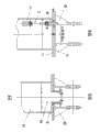
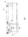
| CN201136742Y (en) | Self-turning and rail type gantry crane for containers | |
| CN202400745U (en) | Trusswork portal crane | |
| CN202916693U (en) | Low-bed submerged magnetic navigation AGV | |
| CN109231026B (en) | Hoisting device for key parts of offshore wind turbine generator | |
| CN201751078U (en) | Automatic feeder of car body top cover | |
| CN205933065U (en) | Container intelligence handling device in storehouse | |
| CN203111182U (en) | Universal-wheel type rail transportation trolley | |
| CN208843671U (en) | A kind of novel wind power tower transloading equipment | |
| CN107902565A (en) | A kind of industrial process waters mud lifting device | |
| CN207646615U (en) | A kind of New-Type Bridge Girder Erection Machine | |
| CN115874594A (en) | Translation load receiving system and translation load receiving method for ocean booster station | |
| CN205575471U (en) | Reducing jar body hoisting device on power station desulfurization absorption tower | |
| CN205168829U (en) | Can extend deck jack -up platform | |
| CN201151618Y (en) | Tyre type self-jacking wheel set | |
| CN210064948U (en) | High-precision double-hook full-rotation European hoisting crane | |
| CN211736302U (en) | Automatic walking multifunctional operation platform for tank construction | |
| CN211169591U (en) | Quick dismounting and transferring device for container |
Legal Events
| Date | Code | Title | Description |
|---|---|---|---|
| C14 | Grant of patent or utility model | ||
| GR01 | Patent grant | ||
| EE01 | Entry into force of recordation of patent licensing contract |
Assignee: Nantong Zhenhua Heavy Equipment Manufacturing Co., Ltd. Assignor: Gangji Heavy-Industry Co., Ltd., Shanghai Contract fulfillment period: 2007.12.1 to 2015.11.30 Contract record no.: 2009320001179 Denomination of utility model: Self-steering orbit type container straddle truck and steering method thereof Granted publication date: 20081022 License type: Exclusive license Record date: 20090721 |
|
| LIC | Patent licence contract for exploitation submitted for record |
Free format text: EXCLUSIVE LICENSE; TIME LIMIT OF IMPLEMENTING CONTACT: 2007.12.1 TO 2015.11.30; CHANGE OF CONTRACT Name of requester: NANTONG ZHENHUA HEAVY EQUIPMENT MANUFACTURING CO., Effective date: 20090721 |
|
| CF01 | Termination of patent right due to non-payment of annual fee |
Granted publication date: 20081022 Termination date: 20141129 |
|
| EXPY | Termination of patent right or utility model |