CN201109708Y - Flow switching control valve for filling mechanical materiel - Google Patents
Flow switching control valve for filling mechanical materiel Download PDFInfo
- Publication number
- CN201109708Y CN201109708Y CNU2007201734347U CN200720173434U CN201109708Y CN 201109708 Y CN201109708 Y CN 201109708Y CN U2007201734347 U CNU2007201734347 U CN U2007201734347U CN 200720173434 U CN200720173434 U CN 200720173434U CN 201109708 Y CN201109708 Y CN 201109708Y
- Authority
- CN
- China
- Prior art keywords
- materiel
- control valve
- discharge hole
- switch door
- discharge nozzle
- Prior art date
- Legal status (The legal status is an assumption and is not a legal conclusion. Google has not performed a legal analysis and makes no representation as to the accuracy of the status listed.)
- Expired - Fee Related
Links
Images

Landscapes
- Basic Packing Technique (AREA)
Abstract
The utility model relates to a materiel flowing switching control pilot used for a semiliquid filling mechanism, which comprises a materiel control pilot or a discharge hole on-off door. The materiel control pilot of the utility model is arranged at the discharge hole of a filling mechanism storage silo. The discharge hole on-off door is arranged at the discharge hole of the materiel control pilot. A valve seat of the materiel control valve is provided with three through holes which are corresponding to three valve core holes of a valve core arranged inside the valve seat, thereby the effective discharge area of materiel is kept to be largest at connecting time and the materiel containing bulky grain can successfully pass to ensure the filling measure and computation to run on the rails. The discharge hole on-off door is arranged at the discharging nozzle of the materiel control valve to ensure the discharge hole on-off door to be closed at the same time when the materiel control valve is closed, thereby avoiding water-clock phenomenon of the subsistence materiel in lager diameter discharging pipes. The discharge hole on-off door which has a small bulk can be arranged at the position with smaller space in a filling container. The materiel flowing switching control pilot is normalized and series. The materiel control valve and the discharge hole on-off door can be synchronously or respectively fixed and applied, thereby adapting to different specification types of automatic and semi-automatic filling mechanisms and the filling units of the silting parts in the packaging mechanisms.
Description
Technical field
The utility model belongs to valve field, relates to a kind of Flow of Goods and Materials switching control pilot that is used for the semifluid filling machine.
Background technology
The Flow of Goods and Materials control cock of known filling machine mainly is made up of valve seat and spool, and its valve seat is provided with hole and storage bin, and metering cylinder and discharge nozzle connect, and is mutually 90 degree positions; Be provided with into the T type hole of 90 degree in its spool, the column type spool back and forth rotates in the column type endoporus of the garden of valve seat, and the reciprocal rotation of spool promotes by the at the uniform velocity swinging gear that connects spool; Connect storage bin and metering cylinder in the work on request, make material flow into metering cylinder, close the storage bin outlet then and connect metering cylinder and discharge nozzle, material is released by piston from metering cylinder, pour into container through discharge nozzle.
Above-mentioned existing Flow of Goods and Materials control cock, on structure design, have the following disadvantages: be to make 90 degree at the uniform velocity back and forth to rotate during owing to spool work, the payload space of the connection holes on the spool and each hole on the valve seat its connection when connecting at the uniform velocity fades to minimum by little to maximum again, thereby makes that bigger solid granulates can't pass through smoothly in the material; Again because valve volume is bigger, when the vessel space of can hour, can only be installed in position away from the discharging mouth of pipe; Moreover because will be by the material of larger particles, the diameter of discharge nozzle must design bigger, when stopping can, though control cock is closed, be deposited in than the material in the major diameter discharge nozzle, can be owing to the uncontrollable discharging mouth of pipe that flows out, cause water clock to pollute, and influence metering effect, make filling apparatus when running into the material that contains larger particles, can't normal operation.
Summary of the invention
The purpose of this utility model is to provide a kind of material that contains big solid granulates that makes to pass through smoothly, and prevents the Flow of Goods and Materials switching control pilot of the filling machine of discharging opening material water clock.
The technical solution adopted in the utility model: a kind of Flow of Goods and Materials switching control pilot of filling machine, comprise material control valve or discharging opening switch door, its material control valve is installed in the discharging opening place of filling machine storage bin, and discharging opening switch door is installed in the discharging opening place of material control valve; The valve seat of described material control valve is provided with three through holes, and is corresponding with three spool bore of spool in being arranged on valve seat.
Described valve seat is a tetragonal body, and top connects with storage bin, and the rear portion connects rear stub, the anterior forward flange dish that connects, and the right side connects the metering cylinder barrel, and the left side connects discharge nozzle.
Be provided with piston in the described metering cylinder barrel, the movable connection piston rod of piston.
Described spool rear flange is passed rear stub and is connected rotary cylinder by coupling sleeve.
Three through holes of described valve seat communicate with storage bin tapping channel, discharge nozzle passage, metering cylinder barrel passage respectively.
The discharge nozzle of described discharging opening switch door connects with the discharge nozzle of material control valve, and the discharge nozzle outside connects stay bearing plate, and the switch door is actively connected on the stay bearing plate, and joystick is actively connected on the switch door, and place, switch doorway is provided with packing seal.
The positive beneficial effect that the utility model had:
1. the spool bore of material control valve is corresponding with valve seat orifice, makes the payload space that material passes through when connecting keep maximum, and containing oarse-grained material can pass through smoothly, ensures that filling measurement is working properly to carry out;
2. the discharging mouth of pipe place of material control valve is provided with discharging opening switch door, and when the material control valve cut out, discharging opening switch door was closed simultaneously, prevents from weeping to occur than the retention material in the major diameter discharge nozzle;
3. discharging opening switch door volume is little, can be installed in less position, container filling space, and the material of being convenient to the control cock outflow pours into the less container in space;
4. compact conformation, specification seriesization, material control valve and discharging opening switch door can be installed and used at the same time or separately, can extensively be suitable for all size model automatically and the can of Semi-automatic machine for feeding bottles tool and package packing machine stowage unit partly install and use.
Description of drawings
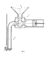
Fig. 1 is positioned at filling machine position scheme drawing for the utility model;
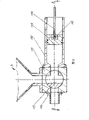
Fig. 2 is the utility model structural representation;
Fig. 3 is the front view of material control valve arrangement scheme drawing of the present utility model;
Fig. 4 is the birds-eye view of material control valve arrangement scheme drawing of the present utility model;
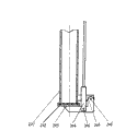
Fig. 5 is a discharging opening switch door scheme drawing of the present utility model.
The specific embodiment
Consult Fig. 1, shown in Figure 2, a kind of Flow of Goods and Materials switching control pilot of filling machine, mainly comprise material control valve 1 and discharging opening switch door 2 two parts, its material control valve 1 is installed in the discharging opening place of filling machine storage bin 3, and discharging opening switch door 2 is installed in the discharging opening place of material control valve 1; Described material control valve 1 and discharging opening switch door 2 can use simultaneously, are installed on the filling machine, also can use respectively, only install material control cock 1 or discharging opening switch door 2 one of them.
Consult Fig. 3, shown in Figure 4, described material control valve 1 part mainly comprises valve seat 101, metering cylinder barrel 102, piston 103, piston rod 104, discharge nozzle 105, rotary cylinder 106, spool 107, bearing pin 108, coupling sleeve 109, rear stub 110, forward flange dish 111 etc.; Its valve seat 101 is a tetragonal body, and top connects with storage bin 3, and the rear portion is connected with rear stub 110, and the front portion is connected with forward flange dish 111, and the right side is connected with metering cylinder barrel 102, and the left side is connected with discharge nozzle 105; Last, the left and right portion of valve seat 101 are provided with three through holes, communicate with tapping channel, discharge nozzle 105 passages, metering cylinder barrel 102 passages of storage bin 3 respectively; Be provided with spool 107 in the valve seat 101, spool 107 is provided with and is three spool bore that the T type distributes, during rotation respectively with valve seat 101 on go up, left and right three through holes communicate or shutoff, realize switch; Be provided with piston 103 in the metering cylinder barrel 102, piston 103 is by bearing pin 108 movable connection piston rods 104; Described spool 107 rear flange are passed rear stub 110, and by coupling sleeve 109 connection rotary cylinders 106, when pressurized air is connected rotary cylinder 106, when rotary cylinder 106 moments drive spool 107 is done 90 degree rotations, make three corresponding connections of through hole on three spool bore and the valve seat 101 on the spool 107, guarantee the maximum payload space that material passes through.
The working process of the utility model material control valve 1: when piston 103 moves right by piston rod 104 pullings, pressurized air promotes rotary cylinder 106 and drives 107 moments of spools and forward position among the figure to, three spool bore on the spool 107 are communicated with storage bin 3 with metering cylinder barrel 102, seal discharge nozzle 105 imports simultaneously, under the negative pressure effect, material is sucked in the metering cylinder barrel 102 from storage bin 3; When piston 103 promotes to be moved to the left by piston rod 104, rotary cylinder 106 drives 107 moments of spools and clockwise rotates 90 degree, three T type spool bore of spool 107 will be measured cylinder barrel 102 and will be communicated with discharge nozzle 105, seal storage bin 3 outlets simultaneously, make material in metering cylinder barrel 102, be pushed discharge nozzle 105 by piston 103, after material all is pushed out, pressurized air promotes rotary cylinder 106 and drives 107 moments of spools and rotate counterclockwise 90 degree, get back to position among the figure, connect storage bin 3, sealing discharge nozzle 105 inlets are finished expendable.The material that flows out when material control valve 1 can connect long discharge nozzle 105 when pouring into the less container in space.
Consult shown in Figure 5ly, described discharging opening switch door 2 parts mainly comprise discharge nozzle 201, packing seal 202, switch door 203, joystick 204, stay bearing plate 205, bearing pin 206 etc.; Its discharge nozzle 201 connects with the discharge nozzle 105 of material control valve 1, discharge nozzle 201 outer lower portion are connected with stay bearing plate 205, switch door 203 is actively connected on the stay bearing plate 205 by bearing pin 206, joystick 204 is actively connected on the switch door 203 by bearing pin 206, switch door 203 is by the switch of joystick 204 realizations with discharge nozzle 201 mouths of pipe, 203 mouthfuls of places of switch door are provided with rubber gasket 202, sealing when being used for switch door 203 sealing discharge nozzles 201 mouths of pipe, after switch door 203 closures, joystick 204 and discharge nozzle 201 axially parallels.
The working process of the utility model discharging opening switch door 2: described joystick 204 connects a straight line motion cylinder, pressurized air promotes the moment that material enters discharge nozzle 201, joystick 204 downward pull switch doors 203, the bearing pin 206 of switch door 203 on stay bearing plate 205 rotates, packing seal 202 moves downward with switch door 203, open the mouth of pipe of discharge nozzle 201 this moment, and material is pushed out outside the discharge nozzle 201, and enters container; When the moment that stops can, the straight-line motion cylinder upwards spurs joystick 204, and joystick 204 is Drawing switch door 203 upwards, packing seal 202 is with switch door 203 upward movements, switch door 203 is closed,, the discharge nozzle 201 interior materials of retaining can not be flowed out the mouth of pipe sealing of discharge nozzle 201.
Claims (6)
1. the Flow of Goods and Materials switching control pilot of a filling machine comprises material control valve or discharging opening switch door, and its material control valve is installed in the discharging opening place of filling machine storage bin, and discharging opening switch door is installed in the discharging opening place of material control valve; The valve seat (101) that it is characterized in that described material control valve (1) is provided with three through holes, and three spool bore of the spool (107) interior with being arranged on valve seat (101) are corresponding.
2. the Flow of Goods and Materials switching control pilot of filling machine according to claim 1, it is characterized in that described valve seat (101) is a tetragonal body, top connects with storage bin (3), the rear portion connects rear stub (110), the anterior forward flange dish (111) that connects, the right side connects metering cylinder barrel (102), and the left side connects discharge nozzle (105).
3. the Flow of Goods and Materials switching control pilot of filling machine according to claim 2 is characterized in that being provided with in the described metering cylinder barrel (102) piston (103), the movable connection piston rod of piston (103) (104).
4. the Flow of Goods and Materials switching control pilot of filling machine according to claim 1 is characterized in that described spool (107) rear flange passes rear stub (110) and connect rotary cylinder (106) by coupling sleeve (109).
5. the Flow of Goods and Materials switching control pilot of filling machine according to claim 1 and 2 is characterized in that three through holes of described valve seat (101) communicate with storage bin (3) tapping channel, discharge nozzle (105) passage, metering cylinder barrel (102) passage respectively.
6. the Flow of Goods and Materials switching control pilot of filling machine according to claim 1 and 2, the discharge nozzle (201) that it is characterized in that described discharging opening switch door (2) connects with the discharge nozzle (105) of material control valve (1), discharge nozzle (201) outside connects stay bearing plate (205), switch door (203) is actively connected on the stay bearing plate (205), joystick (204) is actively connected on the switch door (203), and switch door (a 203) mouthful place is provided with packing seal (202).
Priority Applications (1)
| Application Number | Priority Date | Filing Date | Title |
|---|---|---|---|
| CNU2007201734347U CN201109708Y (en) | 2007-09-28 | 2007-09-28 | Flow switching control valve for filling mechanical materiel |
Applications Claiming Priority (1)
| Application Number | Priority Date | Filing Date | Title |
|---|---|---|---|
| CNU2007201734347U CN201109708Y (en) | 2007-09-28 | 2007-09-28 | Flow switching control valve for filling mechanical materiel |
Publications (1)
| Publication Number | Publication Date |
|---|---|
| CN201109708Y true CN201109708Y (en) | 2008-09-03 |
Family
ID=39894234
Family Applications (1)
| Application Number | Title | Priority Date | Filing Date |
|---|---|---|---|
| CNU2007201734347U Expired - Fee Related CN201109708Y (en) | 2007-09-28 | 2007-09-28 | Flow switching control valve for filling mechanical materiel |
Country Status (1)
| Country | Link |
|---|---|
| CN (1) | CN201109708Y (en) |
Cited By (2)
| Publication number | Priority date | Publication date | Assignee | Title |
|---|---|---|---|---|
| CN110015467A (en) * | 2018-01-09 | 2019-07-16 | 巴斯夫新材料有限公司 | Package packing machine and its discharging tube assembly |
| CN114162396A (en) * | 2021-12-24 | 2022-03-11 | 舟山市金奇食品机械有限公司 | Drawer type high-speed particle filling machine |
-
2007
- 2007-09-28 CN CNU2007201734347U patent/CN201109708Y/en not_active Expired - Fee Related
Cited By (2)
| Publication number | Priority date | Publication date | Assignee | Title |
|---|---|---|---|---|
| CN110015467A (en) * | 2018-01-09 | 2019-07-16 | 巴斯夫新材料有限公司 | Package packing machine and its discharging tube assembly |
| CN114162396A (en) * | 2021-12-24 | 2022-03-11 | 舟山市金奇食品机械有限公司 | Drawer type high-speed particle filling machine |
Similar Documents
| Publication | Publication Date | Title |
|---|---|---|
| JP2591744Y2 (en) | Dispenser for liquid discharge with liquid enclosing cartridge storage case | |
| WO2017147813A1 (en) | Intelligent control-based assembly line filling device | |
| CN212196021U (en) | Automatic liquid sugar filling device | |
| CN101927228B (en) | Extrusion coating machine and coating system thereof | |
| CN201109708Y (en) | Flow switching control valve for filling mechanical materiel | |
| CN201568609U (en) | Ice-cream filling valve | |
| CN111013435B (en) | Mixing equipment for paint dilution | |
| CN209533688U (en) | A kind of discharging device of 3D printer | |
| CN204769263U (en) | Coating blowing jar of steerable flow | |
| EP1535659A1 (en) | Module, system and method of dosing and mixing pasty products | |
| CN211920835U (en) | Automatic quantitative filling device for paste | |
| CN205634853U (en) | Filling cap screwing machine's filling device | |
| CN201485254U (en) | Horizontal filling device | |
| CN204824106U (en) | Liquid filling machine combination formula filling head | |
| CN211538268U (en) | Spraying auxiliary device is used in elevator production and processing | |
| CN214262562U (en) | Two-component glue dispenser | |
| CN211108141U (en) | Filling device is used in glue production | |
| CN209181896U (en) | A kind of precision weighing apparatus | |
| CN220595336U (en) | Aluminum silver paste filling device | |
| CN214930830U (en) | Filling device | |
| CN111674586A (en) | Automatic liquid packaging machine with quantitative filling structure | |
| CN220244095U (en) | Liquid outlet nozzle with valve for liquid soft package bag | |
| CN220076744U (en) | Food filling machine with quantitative control structure | |
| CN217450000U (en) | High-speed mixing granulator | |
| CN219503098U (en) | AB glue mixing device of storage battery glue dispenser |
Legal Events
| Date | Code | Title | Description |
|---|---|---|---|
| C14 | Grant of patent or utility model | ||
| GR01 | Patent grant | ||
| DD01 | Delivery of document by public notice |
Addressee: Yu Beipei Document name: Notification of Termination of Patent Right |
|
| C17 | Cessation of patent right | ||
| CF01 | Termination of patent right due to non-payment of annual fee |
Granted publication date: 20080903 Termination date: 20110928 |