CN200964629Y - Building capable of moving - Google Patents
Building capable of moving Download PDFInfo
- Publication number
- CN200964629Y CN200964629Y CN 200620148340 CN200620148340U CN200964629Y CN 200964629 Y CN200964629 Y CN 200964629Y CN 200620148340 CN200620148340 CN 200620148340 CN 200620148340 U CN200620148340 U CN 200620148340U CN 200964629 Y CN200964629 Y CN 200964629Y
- Authority
- CN
- China
- Prior art keywords
- column
- movably
- way
- connection
- shaped
- Prior art date
- Legal status (The legal status is an assumption and is not a legal conclusion. Google has not performed a legal analysis and makes no representation as to the accuracy of the status listed.)
- Expired - Fee Related
Links
- 229910000831 Steel Inorganic materials 0.000 claims description 5
- 239000010959 steel Substances 0.000 claims description 5
- 238000010276 construction Methods 0.000 abstract description 4
- 238000012423 maintenance Methods 0.000 abstract description 2
- 238000004519 manufacturing process Methods 0.000 abstract description 2
- 238000005728 strengthening Methods 0.000 abstract 1
- 238000010586 diagram Methods 0.000 description 5
- 238000009413 insulation Methods 0.000 description 3
- 238000009408 flooring Methods 0.000 description 2
- 230000002265 prevention Effects 0.000 description 2
- 238000009435 building construction Methods 0.000 description 1
- 239000002131 composite material Substances 0.000 description 1
- 230000002950 deficient Effects 0.000 description 1
- 238000005516 engineering process Methods 0.000 description 1
- 239000003344 environmental pollutant Substances 0.000 description 1
- 231100000719 pollutant Toxicity 0.000 description 1
Images


Landscapes
- Steps, Ramps, And Handrails (AREA)
Abstract
The utility model discloses a new movable building which belongs to the house that is assembled by elements and is built on the construction site with elements. Columns and girders of the building are fixed with screws by hole-passing boards; the through-hole boards are respectively an angle position with triple exits, an angle with four exits, a medium edge with five exits and a medium edge with six exits. The columns are respectively a square column, a marunaka column, a semicircle medium column and a 3/4 fillet column. The girders are respectively square beams and cantilever beams which are provided with eave plates. Hose-shaped strengthening connectors are provided in the floors. And the connectors are respectively a line-two-way-shaped a cross- four-way -shaped, a vertical-three-way-shaped and a two-way elbow-shaped. The wall boards are integrated sandwich wall boards, and also can be sandwich wall boards with windows, thus the utility model solved the shortcomings of bad movability, unreasonable structure and bad fire-prevention in the prior art of movable houses. The utility model has advantages of easy production and maintenance, low cost, long life, superior performance, and can be used widely in fast-installing of all kinds of houses.
Description
Affiliated technical field
It is a kind of by member house assembled building that the utility model belongs to, and is the building that assembles with member at the construction field (site).
Background technology
Existing to use prefabricated component assembled house building very general, but its ubiquity mobility is poor, overall structure is unreasonable and defective such as difficult fire prevention, thereby be difficult to apply.
Summary of the invention
In order to overcome the existing prefabricated component assembled house building above shortcomings of using, this reality is novel to provide a kind of improved movably novel building that assembles with member.
The purpose of this utility model is achieved in that and comprises some columns, some ends all are fixed on the crossbeam on the column, some withstand on the flooring element on these crossbeams and the movably novel building of wallboard and stair step, its design feature is: column and crossbeam be by port plate bolt, and described port plate be respectively the threeway of top, angle, angle four-way, middle limit five-way and in six lead to.Column is respectively box type column, circle central post, semicircle central post and 3/4ths fillet columns.Crossbeam is respectively outrigger and the square beam that is provided with the eaves plate.Be provided with the tubulose part that reinforces the connection in the floor, and it is respectively straight line two logical shapes, intersects four-way shape, vertical threeway shape and elbow two logical shapes.Wallboard is whole combined wall board, and it can be the whole combined wall board of band door and window.The floor is fixed by the angle steel that is arranged on the crossbeam.Below column, be provided with base for post.
The utility model has the advantages that: adopt building construction that 24 members are formed, that can make things convenient for integral body to move and remove.It has compact conformation, job site noiselessness and pollutant, superpower antidetonation, and winter protection, fire prevention, waterproof, anti-electricity, save time, save money advantages such as sound insulation, insulation, insulation at the saving of labor.And its manufacturing is simple, easy to maintenance, cost is low, superior performance, durable in use.
Description of drawings
The utility model will be further described below in conjunction with drawings and Examples.
Fig. 1 is a structural representation of the present utility model
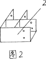
Fig. 2-5 is the port plated construction schematic diagram of utility model
Fig. 6-9 is a pillar construction schematic diagram of the present utility model
Figure 10 is a base for post structural representation of the present utility model
Figure 11-12 is a crossbeam structural representation of the present utility model
Figure 13-14 is an angle steel structural representation of the present utility model
Figure 15-18 is the tubulose of the present utility model part structural representation that reinforces the connection
Figure 19 is a bolt arrangement schematic diagram of the present utility model
Figure 20 is a stair step structural representation of the present utility model
Figure 21-22 is a flooring structure schematic diagram of the present utility model
Figure 23-24 is a whole composite wallboard structure schematic diagram of the present utility model
Among the figure: 1, the threeway of top, angle, 2, the angle four-way, 3, middle limit five-way, 4, in six logical, 5, box type column, 6, the circle central post, 7, the semicircle central post, 8,3/4ths fillet columns, 9, base for post, 10, outrigger, 11, square beam, 12,13 angle steel, 14, the logical shapes of straight line two part that reinforces the connection, 15, the four-way shape that the intersects part that reinforces the connection, 16, the vertical threeway shape part that reinforces the connection, 17, the logical shapes of elbow two part that reinforces the connection, 18, bolt, 19, stair step, 20, the eaves plate, 21, Roofing slab, 22, the floor, 23, the whole combined wall board of band window, 24, the whole combined wall board of band door.
The specific embodiment:
Shown in Fig. 1-2 4, comprise some columns 5,6,7,8, some ends all are fixed on the crossbeam 10,11 on the column 5,6,7,8, some withstand on floor 22 members on these crossbeams and the movably novel building of wallboard 23,24 and stair step 19, its design feature is: column 5,6,7,8 and crossbeam 10,11 is fixing by port plate 1,2,3,4 usefulness bolts 18, and described port plate 1,2,3,4 be respectively top, angle threeway 1, angle four-way 2, middle limit five-way 3 and in six lead to 4. Column 5,6,7,8 is respectively box type column 5, circle central post 6, semicircle central post 7 and 3/4ths fillet columns 8.Crossbeam 10,11 is respectively outrigger 10 and the square beam 11 that is provided with eaves plate 20.Be provided with the tubulose part 14,15,16,17 that reinforces the connection in the floor 22 (top board 21), and it is respectively straight line two logical shapes part 14, the four-way shape that intersects part 15, vertical threeway shape part 16 and the elbow two logical shapes part 17 that reinforces the connection that reinforces the connection that reinforces the connection that reinforces the connection.Wallboard 23,24 is whole combined wall board, and it can be the whole combined wall board 24,23 of band door and window.Floor 22 is fixing by the angle steel 12,13 that is arranged on the crossbeam 10,11.Below column 5,6,7,8, be provided with base for post 9.
Claims (7)
1, a kind of movably novel building, comprise some columns (5,6,7,8), some ends all are fixed on the crossbeam (10,11) on the column (5,6,7,8), some withstand on floor (22) member and wallboard (23,24) and stair step (19) on these crossbeams, it is characterized in that: column (5,6,7,8) and crossbeam (10,11) are fixing with bolt (18) by port plate (1,2,3,4), and described port plate (1,2,3,4) be respectively top, angle threeway (1), angle four-way (2), middle limit five-way (3) and in six lead to (4).
2, movably novel building as claimed in claim 1 is characterized in that described column (5,6,7,8) is respectively box type column (5), circle central post (6), semicircle central post (7) and 3/4ths fillet columns (8).
3, movably novel building as claimed in claim 1 is characterized in that described crossbeam (10,11) is respectively outrigger (10) and the square beam (11) that is provided with eaves plate (20).
4, pipe as claimed in claim 1 novel building movably, it is characterized in that being provided with in the described floor (22) the tubulose part (14,15,16,17) that reinforces the connection, and it is respectively straight line two logical shapes part (14), the four-way shape that intersects reinforce the connection part (16) and the elbow two of part (15), vertical threeway shape that reinforce the connection that reinforce the connection and leads to the shapes part (17) that reinforces the connection.
5, movably novel building as claimed in claim 1 is characterized in that described wallboard (23,24) is whole combined wall board, and it can be the whole combined wall board (24,23) of band door and window.
6,, it is characterized in that described floor (22) is fixing by the angle steel (12,13) that is arranged on the crossbeam (10,11) as claim 1,4 described movably novel buildings.
7, movably novel building as claimed in claim 1 is characterized in that being provided with base for post (9) in the below of column (5,6,7,8).
Priority Applications (1)
| Application Number | Priority Date | Filing Date | Title |
|---|---|---|---|
| CN 200620148340 CN200964629Y (en) | 2006-10-24 | 2006-10-24 | Building capable of moving |
Applications Claiming Priority (1)
| Application Number | Priority Date | Filing Date | Title |
|---|---|---|---|
| CN 200620148340 CN200964629Y (en) | 2006-10-24 | 2006-10-24 | Building capable of moving |
Publications (1)
| Publication Number | Publication Date |
|---|---|
| CN200964629Y true CN200964629Y (en) | 2007-10-24 |
Family
ID=38868642
Family Applications (1)
| Application Number | Title | Priority Date | Filing Date |
|---|---|---|---|
| CN 200620148340 Expired - Fee Related CN200964629Y (en) | 2006-10-24 | 2006-10-24 | Building capable of moving |
Country Status (1)
| Country | Link |
|---|---|
| CN (1) | CN200964629Y (en) |
Cited By (2)
| Publication number | Priority date | Publication date | Assignee | Title |
|---|---|---|---|---|
| CN101798847B (en) * | 2010-02-05 | 2012-06-27 | 杜海平 | Unit-modularized house |
| CN102561728A (en) * | 2011-12-22 | 2012-07-11 | 苏州金螳螂建筑装饰股份有限公司 | Recyclable steel-skeleton model-house system |
-
2006
- 2006-10-24 CN CN 200620148340 patent/CN200964629Y/en not_active Expired - Fee Related
Cited By (3)
| Publication number | Priority date | Publication date | Assignee | Title |
|---|---|---|---|---|
| CN101798847B (en) * | 2010-02-05 | 2012-06-27 | 杜海平 | Unit-modularized house |
| CN102561728A (en) * | 2011-12-22 | 2012-07-11 | 苏州金螳螂建筑装饰股份有限公司 | Recyclable steel-skeleton model-house system |
| CN102561728B (en) * | 2011-12-22 | 2014-10-29 | 苏州金螳螂建筑装饰股份有限公司 | Recyclable steel-skeleton model-house system |
Similar Documents
| Publication | Publication Date | Title |
|---|---|---|
| CN102979172B (en) | Industrialized assembled multi-story high-rise steel structure prestressed centrally-braced system | |
| CN102979165B (en) | Industrialized assembled multi-story high-rise steel structure centrally-braced system | |
| WO2017076070A1 (en) | Integrated-assembly steel structure building | |
| CN201521058U (en) | Building cold bending thin-wall truss type floor beam | |
| CN205444458U (en) | Integrated assembled steel construction building | |
| CN102979171A (en) | Industrialized assembled multi-story high-rise steel structure frame system | |
| CN102979173B (en) | Industrialized assembled multi-story high-rise steel structure prestressed eccentrically-braced system | |
| CN205296407U (en) | Embedded steel construction assembly house post roof beam connection structure | |
| CN205296452U (en) | Embedded steel construction assembly house stand fire resistive construction | |
| CN2793179Y (en) | Assembled house structural system | |
| CN200964629Y (en) | Building capable of moving | |
| CN205475677U (en) | Steel house room unit | |
| CN103206012B (en) | A kind of industrialization assembling is many, Tall Frameworks support system | |
| CN1587560A (en) | Composite building construction member of cold bending thin wall lattice configuration steel and concrete and its producing method | |
| CN202000473U (en) | Lattice beam | |
| CN1243167C (en) | Building structure and installing method for two-layer movable panel house | |
| CN205296607U (en) | Embedded steel construction assembly house roof boarding mounting structure | |
| CN2739258Y (en) | Two-storey movable dwelling building structure | |
| CN201521057U (en) | Building cold bending thin-wall truss type door and window lintel | |
| CN1222671C (en) | Building structure and installing method for two-layer movable panel house | |
| CN203856132U (en) | Cold-formed thin-walled arch-shaped roof truss for buildings | |
| CN2778915Y (en) | Detachable combination house | |
| CN1632252A (en) | Light steel sealed column framework construction system | |
| CN210421381U (en) | Evaporate and press whole house of aerated concrete slab | |
| CN2721746Y (en) | Semi-unit glass curtain wall |
Legal Events
| Date | Code | Title | Description |
|---|---|---|---|
| C14 | Grant of patent or utility model | ||
| GR01 | Patent grant | ||
| C17 | Cessation of patent right | ||
| CF01 | Termination of patent right due to non-payment of annual fee |
Granted publication date: 20071024 Termination date: 20091124 |