CN1983803A - Class D amplifier - Google Patents
Class D amplifier Download PDFInfo
- Publication number
- CN1983803A CN1983803A CNA2006101693031A CN200610169303A CN1983803A CN 1983803 A CN1983803 A CN 1983803A CN A2006101693031 A CNA2006101693031 A CN A2006101693031A CN 200610169303 A CN200610169303 A CN 200610169303A CN 1983803 A CN1983803 A CN 1983803A
- Authority
- CN
- China
- Prior art keywords
- output
- lead
- out terminal
- channel mos
- signal
- Prior art date
- Legal status (The legal status is an assumption and is not a legal conclusion. Google has not performed a legal analysis and makes no representation as to the accuracy of the status listed.)
- Pending
Links
Images


Classifications
-
- H—ELECTRICITY
- H03—ELECTRONIC CIRCUITRY
- H03F—AMPLIFIERS
- H03F3/00—Amplifiers with only discharge tubes or only semiconductor devices as amplifying elements
- H03F3/20—Power amplifiers, e.g. Class B amplifiers, Class C amplifiers
- H03F3/21—Power amplifiers, e.g. Class B amplifiers, Class C amplifiers with semiconductor devices only
- H03F3/217—Class D power amplifiers; Switching amplifiers
- H03F3/2171—Class D power amplifiers; Switching amplifiers with field-effect devices
-
- H—ELECTRICITY
- H03—ELECTRONIC CIRCUITRY
- H03F—AMPLIFIERS
- H03F1/00—Details of amplifiers with only discharge tubes, only semiconductor devices or only unspecified devices as amplifying elements
- H03F1/26—Modifications of amplifiers to reduce influence of noise generated by amplifying elements
-
- H—ELECTRICITY
- H03—ELECTRONIC CIRCUITRY
- H03F—AMPLIFIERS
- H03F1/00—Details of amplifiers with only discharge tubes, only semiconductor devices or only unspecified devices as amplifying elements
- H03F1/32—Modifications of amplifiers to reduce non-linear distortion
-
- H—ELECTRICITY
- H03—ELECTRONIC CIRCUITRY
- H03F—AMPLIFIERS
- H03F3/00—Amplifiers with only discharge tubes or only semiconductor devices as amplifying elements
- H03F3/20—Power amplifiers, e.g. Class B amplifiers, Class C amplifiers
- H03F3/21—Power amplifiers, e.g. Class B amplifiers, Class C amplifiers with semiconductor devices only
- H03F3/217—Class D power amplifiers; Switching amplifiers
- H03F3/2173—Class D power amplifiers; Switching amplifiers of the bridge type
-
- H—ELECTRICITY
- H03—ELECTRONIC CIRCUITRY
- H03K—PULSE TECHNIQUE
- H03K17/00—Electronic switching or gating, i.e. not by contact-making and –breaking
- H03K17/16—Modifications for eliminating interference voltages or currents
- H03K17/161—Modifications for eliminating interference voltages or currents in field-effect transistor switches
- H03K17/162—Modifications for eliminating interference voltages or currents in field-effect transistor switches without feedback from the output circuit to the control circuit
-
- H—ELECTRICITY
- H03—ELECTRONIC CIRCUITRY
- H03K—PULSE TECHNIQUE
- H03K17/00—Electronic switching or gating, i.e. not by contact-making and –breaking
- H03K17/51—Electronic switching or gating, i.e. not by contact-making and –breaking characterised by the components used
- H03K17/56—Electronic switching or gating, i.e. not by contact-making and –breaking characterised by the components used by the use, as active elements, of semiconductor devices
- H03K17/687—Electronic switching or gating, i.e. not by contact-making and –breaking characterised by the components used by the use, as active elements, of semiconductor devices the devices being field-effect transistors
- H03K17/6871—Electronic switching or gating, i.e. not by contact-making and –breaking characterised by the components used by the use, as active elements, of semiconductor devices the devices being field-effect transistors the output circuit comprising more than one controlled field-effect transistor
- H03K17/6872—Electronic switching or gating, i.e. not by contact-making and –breaking characterised by the components used by the use, as active elements, of semiconductor devices the devices being field-effect transistors the output circuit comprising more than one controlled field-effect transistor using complementary field-effect transistors
-
- H—ELECTRICITY
- H03—ELECTRONIC CIRCUITRY
- H03K—PULSE TECHNIQUE
- H03K17/00—Electronic switching or gating, i.e. not by contact-making and –breaking
- H03K17/51—Electronic switching or gating, i.e. not by contact-making and –breaking characterised by the components used
- H03K17/56—Electronic switching or gating, i.e. not by contact-making and –breaking characterised by the components used by the use, as active elements, of semiconductor devices
- H03K17/687—Electronic switching or gating, i.e. not by contact-making and –breaking characterised by the components used by the use, as active elements, of semiconductor devices the devices being field-effect transistors
- H03K17/6871—Electronic switching or gating, i.e. not by contact-making and –breaking characterised by the components used by the use, as active elements, of semiconductor devices the devices being field-effect transistors the output circuit comprising more than one controlled field-effect transistor
- H03K17/6874—Electronic switching or gating, i.e. not by contact-making and –breaking characterised by the components used by the use, as active elements, of semiconductor devices the devices being field-effect transistors the output circuit comprising more than one controlled field-effect transistor in a symmetrical configuration
-
- H—ELECTRICITY
- H03—ELECTRONIC CIRCUITRY
- H03F—AMPLIFIERS
- H03F2200/00—Indexing scheme relating to amplifiers
- H03F2200/114—Indexing scheme relating to amplifiers the amplifier comprising means for electro-magnetic interference [EMI] protection
-
- H—ELECTRICITY
- H03—ELECTRONIC CIRCUITRY
- H03F—AMPLIFIERS
- H03F2200/00—Indexing scheme relating to amplifiers
- H03F2200/351—Pulse width modulation being used in an amplifying circuit
-
- H—ELECTRICITY
- H03—ELECTRONIC CIRCUITRY
- H03F—AMPLIFIERS
- H03F2200/00—Indexing scheme relating to amplifiers
- H03F2200/372—Noise reduction and elimination in amplifier
-
- H—ELECTRICITY
- H03—ELECTRONIC CIRCUITRY
- H03F—AMPLIFIERS
- H03F2200/00—Indexing scheme relating to amplifiers
- H03F2200/456—A scaled replica of a transistor being present in an amplifier
Abstract
A class D amplifier is provided that is capable of reducing distortion of a specific sampling frequency, and frequencies that are multiples of this frequency to a level where an LPF is not required and small-scale control circuit. A class D amplifier (100) includes: an H full bridge output section (120) having five output states and containing a first outlet (111) and a second outlet (112) in which the fifth output states is high impedance, and an output control section (110) which is consists of a random number generator (103) that takes individual random numbers that do not depend on input values as output values and a PWM control signal generating circuit (104) that generates a final PWM control signal from the input values and output values of random number generator (103). The output control section (110) divides a pulse signal outputted at a reference point between sampling frequencies into a plurality of pulse signals with random widths that do not include the reference point , and outputs the pulse signals with random widths.
Description
Technical field
The present invention relates to the D class A amplifier A that moves by conversion method, particularly relate to by according to (Pulse Width Modulation: pulse-width modulation) switching motion of signal comes pwm signal is carried out power amplification, and thus obtained output signal is offered the D class A amplifier A that is suitable for audio purposes of the load that comprises loud speaker etc. based on the PWM of voice signal etc.
Background technology
Voice signal being amplified and offering loud speaker, from the acoustic device of loud speaker acquisition, can adopt the amplification method of various voice signals according to each purpose based on the voice of voice signal.Especially in the situation that obtains to be used for driving the output signal of loud speaker, modification method is arranged based on input speech signal.About the power amplification of voice signal, use the D class A amplifier A that carries out so-called D class action at the amplifying circuit element of transistor etc.Analog linearity amplifiers such as D class A amplifier A and class ab ammplifier are compared, and can obtain very good power conversion efficiency, because of thermal discharge is little, therefore often are adopted to the speaker drive amplifier.
In the D class A amplifier A, the amplification active element of employed transistor etc. is configured to for example to carry out based on the switching motion as the input signal of voice signal.Then, for example in the power amplification circuit of the amplification of voice signal being used the D class A amplifier A, acquisition is carried out the power amplification of this pwm signal based on the pwm signal of input speech signal, and the scheme that the pwm signal that is subjected to power amplification is offered loudspeaker unit is suggested.
In general, pwm signal was output as pulse signal with the cycle prior decision, that be called as sample frequency.Because this sampling period compares with the higher limit 20kHz of general speech frequency, be very high frequency, in the output signal of D class A amplifier A, comprised the distortion of the frequency of 1/2nd frequency of this sample frequency, this sample frequency and multiplication.
Because this high-frequency distortion makes as the coil rapid deterioration of the basic and main element of loudspeaker unit, in the past when pwm signal is connected to loudspeaker unit, insert LPF (LowPass Filter: low pass filter) use betwixt, and in recent years, having proposed some need be at the D class A amplifier A of necessary LPF in the past.LPF is in order to prevent as the destruction of the speaker circuit of load etc. and to observe the EMI standard of defined and be inserted into.
For example, in the D class A amplifier A that does not need LPF in the past, forward and two reverse pwm signals depend on input signal and are subjected to two ends modulation (end-to-end modulation), reduce the distortion of the specific sample frequency and the frequency of its 1/2nd frequency and multiplication (for example, with reference to patent document 1: No. 6211728 specification of United States Patent (USP)) by getting its difference.
About have or not the reason of the distortion of sample frequency necessity, specific of LPF and its 1/2nd frequency and frequency multiplication, be to result to have specific periodic pulse signal in order to generate so that this sample frequency in advance either party edge etc. of the central point of datum mark and the pulsewidth of for example pwm signal in the time interval of decision or pulse signal is consistent.
Therefore, in the D class A amplifier A that in patent document 1, proposes, control to carry out following actions: serve as zero situation at first in input value, forward and two reverse pwm signals are all exported the interval and interval clock waveform that equates of electronegative potential of high potential, increase along with input value, the edge at the two ends of the pwm signal of forward is based on input value and linear separation, and the edge at the two ends of reverse pwm signal is based on input value and linear approaching.
The differential wave that obtains by this control becomes every two pulse signals in the time interval of decision in advance, and be the pulse signal that carries out following variation, that is, pulse signal is separated from each other based on input value or is approaching, and pulse signal itself also broadens or narrows down.
And the differential wave that obtains by this control is the pwm signal of 3 values, rather than the pwm signal of 2 values in the past.Therefore, the signal amplitude of each pulse of the difference pulse signal that obtains according to this control become 2 values in the past pwm signal each pulse signal amplitude 1/2nd, the harmonic signal and the high-frequency noise that take place at the frequency domain relevant with the EMI standard are eased down to below 1/2nd.
By using such method, in the D class A amplifier A that proposes in patent document 1, the distortion of the frequency of specific sample frequency and its frequency of 1/2nd and multiplication is eased down to the degree that does not need LPF.
And, as existing D class A amplifier A, sample frequency itself is changed randomly, and the D class A amplifier A that lowers the specific sample frequency and the distortion of the frequency of its 1/2nd frequency and multiplication is (for example, with reference to patent document 2: No. 6847257 specification of United States Patent (USP)).
If itself changes sample frequency randomly, by the also variation randomly of datum mark in the time interval of decision in advance of this sample frequency.Therefore, in the D class A amplifier A that proposes in patent document 1, considerable its output signal of measuring does not have the time interval of decision in advance, and earthquake always.By using such method, in the D class A amplifier A that proposes in patent document 2, the distortion of the frequency of specific sample frequency and its frequency of 1/2nd and multiplication is eased down to the degree that does not need LPF.
Yet, in existing like this D class A amplifier A, following problem points is arranged.
In the D class A amplifier A of in patent document 1, putting down in writing, input value is that fixed value or signal are when carrying out small variation, the pwm signal of forward and reverse pwm signal change hardly, therefore the differential wave that obtains by this control becomes at every time interval of decision in advance, two pulse signals that cycle and pulsewidth are almost fixing.Therefore, the distortion of that produce, not specific sample frequency and its 1/2nd frequency and frequency multiplication increases when the situation of input value change.
Even, the D class A amplifier A of record in the patent document 2 is arranged as being that the situation that fixed value or signal carry out minor variations does not have the D class A amplifier A that above-mentioned distortion increases yet in input value.
; in order to realize the circuit of patent document 2 records; need be used to tackle the sample circuit again of the input signal of the sample frequency of change at random always, and be used for complicated and large-scale circuit that the pulsewidth of the pwm signal that changes along with the change of sample frequency and should export is calculated again.
Have again, sometimes the arithmetic eror that causes of the sampling and the change of sample frequency makes new noise and the distortion of D class A amplifier A generation itself again, and the analog circuit that need comprise operational amplifier and electric capacity, impedance of becoming produces as with the triangular wave of the reference signal that generates pwm signal etc., and becoming to prevent the increase of characteristic cracking and circuit scale.
Summary of the invention
Even the object of the present invention is to provide a kind of is the situation that fixed value or signal carry out minor variations in input value, also the distortion of the specific sample frequency and the frequency of its 1/2nd frequency and multiplication can be eased down to the degree that does not need LPF, and the D class A amplifier A that can only realize with simple and small-scale control circuit.
According to an aspect of the present invention, a kind of D class A amplifier A comprises: output unit, the potential difference between first lead-out terminal and second lead-out terminal is exported as differential wave; And output control unit, the pwm control signal of the state variation that makes the potential difference between described first output and described second output is provided, described output control unit comprises: pulse signal generation unit, the pulse signal of datum mark output that will be between sample frequency are divided into do not comprise described datum mark a plurality of and have the pulse signal and the output of width at random.
Description of drawings
By below in conjunction with the description that accompanying drawing carried out, of the present invention above-mentionedly will become more apparent with other purpose and characteristic, below in the description carried out, some examples have been described by way of example, wherein:
Fig. 1 (a)~Fig. 1 (d) is the signal output waveform figure that is used to illustrate basic thought of the present invention.
Fig. 2 (a)~Fig. 2 (d) is used to illustrate the figure of the generation method of the pulse signal of width at random that has of the present invention.
Fig. 3 is the circuit diagram of structure of the D class A amplifier A of expression embodiment of the present invention 1.
Fig. 4 is the block diagram of detailed structure of pwm control signal generation circuit of the D class A amplifier A of the above-mentioned execution mode 1 of expression.
Fig. 5 is expression for the input signal of the D class A amplifier A of above-mentioned execution mode 1 figure for an example of linear pwm signal.
Fig. 6 represents the signal waveforms by the D class A amplifier A generation of above-mentioned execution mode 1.
Fig. 7 is the circuit diagram of structure of the D class A amplifier A of expression embodiment of the present invention 2.
Fig. 8 is the block diagram of detailed structure of pwm control signal generation circuit of the D class A amplifier A of the above-mentioned execution mode 2 of expression.
Fig. 9 (a)~Fig. 9 (e) is the address/output valve of ROM of presentation graphs 8 and the figure of the output waveform that taken place by its.
Figure 10 represents the signal waveforms by the D class A amplifier A generation of above-mentioned execution mode 2.
Figure 11 is the circuit diagram of structure of the D class A amplifier A of expression embodiment of the present invention 3.
Figure 12 is the circuit diagram of structure of the D class A amplifier A of expression embodiment of the present invention 4.
Figure 13 is the circuit diagram of structure of the D class A amplifier A of expression embodiment of the present invention 5.
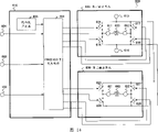
Figure 14 is the circuit diagram of structure of the D class A amplifier A of expression embodiment of the present invention 6.
Figure 15 (a)~Figure 15 (h) is the address/output valve of ROM of presentation graphs 8 and the figure of the output waveform that takes place thus.
Embodiment
Below, the preferred implementation that present invention will be described in detail with reference to the accompanying.
(principle explanation)
Basic thought of the present invention at first is described.
The technology of described patent document 2 records is, by the displacement of sample frequency itself, the distortion of the frequency of specific sample frequency and its 1/2nd frequency and multiplication eased down to the degree that does not need LPF.; in order to realize the circuit of patent document 2 records; need be used to tackle the sample circuit again of the input signal of the sample frequency of change at random always, and be used for complicated and large-scale circuit that the pulsewidth of the pwm signal that changes along with the change of sample frequency and should export is calculated again.
The datum mark that the present invention is conceived to signal output waveform is present in the fact between the sample frequency fs, in the front and back of described datum mark pulse signal is divided at least the signal more than two, directly exported with the described datum mark of pulse signal between sample frequency fs of avoiding signal output waveform.Carry out this cutting apart at random (split position, cut apart number, pattern occurs, frequency etc. takes place at random), and the position of divided each pulse signal also is arbitrarily between sample frequency fs.Sample frequency fs keeps fixing.Therefore, in the datum mark of avoiding between the sample frequency fs, had at random by random division that a plurality of pulse signals of width are output in position at random, therefore the cycle of the pulse signal of datum mark by spread spectrum, makes the specific sample frequency and the distortion of the frequency of its 1/2nd frequency and multiplication be eased down to the degree that does not need LPF at time-axis direction.The dividing method of described pulse signal can be that the certain ration of division with prior decision is divided into a plurality of methods simply, but subtracts the high precision int that is brought in order to raise the efficiency and realize that error is low, cuts apart randomly with the method that describes in detail below.And above-mentioned dividing method can be at random or adaptively modifying.
Fig. 1 is the signal output waveform figure that is used to illustrate basic thought of the present invention.In Fig. 1, sample frequency fs is for fixing.And the dotted line of Fig. 1 is represented the datum mark of sample frequency fs.Fig. 1 (a) is the signal output waveform before cutting apart, and this signal output waveform is cut apart in required time randomly.Fig. 1 (b) is an example of the pwm signal of the signal output waveform after cutting apart of cutting apart randomly, and when the pulse signal that will cut apart synthesized, pulsewidth equated (ignoring the part of compensation) with original pulsewidth.Similarly, Fig. 1 (c) is other the example of pwm signal after cutting apart of cutting apart randomly.As Fig. 1 (b) (c) shown in because signal output waveform is by random division, during pwm signal after cutting apart with certain cycle, becomes and have the combination of the pulse signal of width at random.In addition, the displacement (with reference to b.) randomly of datum mark one side is simultaneously avoided in the position of the pwm signal after also will cutting apart in fixing sample frequency fs.More than for being divided into two example, but as Fig. 1 (d) shown in, also can be divided into three (or more) randomly, the pulse signal after will cutting apart is synthetic, and pulsewidth equates with the pulsewidth of script.For the position that is divided into the pwm signal after three also is similarly, and one side is avoided the displacement randomly of datum mark one side in fixing sample frequency fs.Have again, can regularly be divided into two and be divided into three and switch mutually to above-mentioned aptly in regulation.
As above-mentioned, when appearing at the pwm signal of lead-out terminal with certain chronomere, at the pulse signal of datum mark at time-axis direction by spread spectrum, in other words, differential output signal is for being input as linearity, but the at random pulsewidth of pulse period because of addition becomes irregular, and the distortion of the frequency of specific sample frequency and its frequency of 1/2nd and multiplication is eased down to the degree that does not need LPF.And, with respect in the prior embodiment, owing to the complicated and large-scale circuit that the periodic displacement of sample frequency itself need be used for to the change along with sample frequency changes and the pulsewidth of the pwm signal that should export is calculated again, D class A amplifier A of the present invention is fixing because of sample frequency fs, so can be realized with simple and small-scale control circuit.
Next, illustrate to have the generation of the pulse signal of width at random.
Fig. 2 is used to illustrate the figure of the generation method of the pulse signal of width at random that has of the present invention.Be illustrated in input value=2 o'clock, with input value irrelevant two the generation method of the pulse signal of width at random.
Shown in Fig. 2 (a), the pulse signal output before cutting apart is at pulse signal of each sample frequency output.In general pwm control signal generation circuit, with this pulse signal with being output.
D class A amplifier A of the present invention is controlled, and makes pulse signal by the output of each sample frequency become the combination of the pulse signal of width at random that has more than 2.As an example of its concrete grammar, the structure that is adopted comprises: be used to export differential pwm signal output unit, be used to export and the tandom number generator of the irrelevant random value of input value and the pwm control signal generation circuit that is used to control the pwm control signal of output unit based on this random value and input value output.
So long as be created on the method for the pulse signal more than 2 of simultaneously avoiding datum mark one side random shift in the fixing sample frequency, can be any pulse signal generation method.Below following example will be described:, will not have relatively by the pulse signal of each sample frequency output and cut apart as index with the output valve of tandom number generator, and generate with incoherent two of each input value and have the pulse signal of width at random.Have again, have the situation of the pulse signal of width at random generating, based on following reason, if use differential wave output more suitable with irrelevant two of each input value.
Above-mentioned pulse signal can be realized with any one of single channel output and differential wave output, but use differential wave output characteristic guarantee aspect than the tool advantage, therefore describe as prerequisite with the situation of using differential wave to export.
First output of Fig. 2 (b) expression is the pulse signal of forward, and second output of Fig. 2 (c) expression is reverse pulse signal.Fig. 2 (d) is the output that is generated and cut apart in incoherent mode by above-mentioned two difference pulse signals.Tandom number generator produces the pulse signal of the above-mentioned forward be shown in Fig. 2 (b), Fig. 2 (c) and reverse pulse signal, and is applied to load simultaneously, thus, the potential difference at the two ends of load be applied in the pwm signal shown in Fig. 2 (d) after state equate.Perhaps, generating the pwm signal shown in Fig. 2 (d) in advance by the pwm control signal generation circuit that is made of trigger and logical circuit etc., to be applied to load also passable.Though above-mentioned explanation is the situation of relevant differential wave output,, use by the pwm control signal generation circuit that constitutes by trigger and logical circuit etc. in generate the pwm signal shown in Fig. 2 (d) and be applied to the method for load in advance in the situation of single channel output.
The pwm signal of Xing Chenging is like this, constitute by the potential difference of the pwm signal of forward and reverse pwm signal, have the difference pulse signal of width at random with irrelevant two of each input value.And this difference pulse signal is two pulse signals by each time interval of the prior decision of sample frequency, and the aggregate value and the input value of cutting apart preceding pulsewidth of these two pulse signals are kept man-to-man relation.At Fig. 2, Fig. 2 (a) lattice portion divides input value (=2) output of expression to divide aggregate value (1.5+0.5=2) output of two pulsewidths of expression to equate with Fig. 2 (d) lattice portion.Thus, between the input value and differential output valve to the D class A amplifier A, the I/O characteristic of compensated linear at first.
At the above-mentioned cut-point that do not make is at random the situation, frequency in characteristic frequency corresponding with this cut-point and multiplication has the harmonic component of peak value, and the power of high-frequency domain is concentrated and increase in characteristic frequency, if therefore do not add LPF, might destroy as the speaker circuit of load etc., and might observe the EMI standard of regulations such as VCCI and FCC part15.
In other words, make cut-point at random, can make the higher harmonic wave component that depends on sample frequency and cut-point be evenly dispersed in whole high-frequency region, its result can prevent the power concentration in characteristic frequency, can not safeguard speaker circuit and above-mentioned EMI standard even do not add LPF yet, make use become possibility as so-called no filtering (filterless) as load.
In addition, be used to generate the pwm signal of above-mentioned forward and the reverse needed tandom number generator of pwm signal in fact can be as mould pseudorandom generator (modulo pseudo-random generator) with the trigger of only a few and " different " (XOR) circuit realized, for pwm control signal generation circuit, also can with relatively small number of triggers, selector, adder, counter, reverser and " with " (AND), " or " (OR) etc. basic logic element combination or used the circuit of ROM simply and on a small scale to be realized.
(execution mode 1)
Fig. 3 is the circuit diagram of expression based on the structure of the D class A amplifier A of above-mentioned basic thought embodiment of the present invention 1.Present embodiment is to be suitable for and will to offer the utilization example of D class A amplifier A of audio frequency of pwm signal output of the inductive load of loud speaker etc.
In Fig. 3, the structure of D class A amplifier A 100 comprises: by input terminal 101, mute signal input terminal 102, the output control unit 110 that tandom number generator 103 and pwm control signal generation circuit 104 constitutes, and by first and second lead- out terminal 111 and 112 of the inductive load 150 that connects loud speaker etc., first power supply terminal 113 of first current potential is provided, the second source terminal 114 of second current potential is provided, first switch 115 that connects first power supply terminal 113 and first lead-out terminal 111, the second switch 116 that connects first lead-out terminal 111 and second source terminal 114, connect the 3rd switch 117 of first power supply terminal 113 and second lead-out terminal 112 and the output unit 120 of the 4th switch 118 formations that are connected second lead-out terminal 112 and second source terminal 114.
Output unit 120 generally has the circuit structure that is called as H full-bridge (H (full) bridge) formula.The function that is widely known by the people most as the advantage of the output unit of H full-bridge type is even connect inductive load 150 between first lead-out terminal 111 and second lead-out terminal 112, also can suppress to be called as the distinctive power supply noise of regenerative current.
Output unit 120 has first lead-out terminal 111 and second lead-out terminal 112, first lead-out terminal 111 and second lead-out terminal 112 are exported the PWM modulation waveform respectively, make current potential become first current potential in the Hi interval, second current potential that becomes in the Lo interval, and the potential difference of first lead-out terminal 111 and second lead-out terminal 112 is exported as final differential wave.In more detail, providing of a plurality of control signals that generate by the input value of using toward output control unit 110, output unit 120 has five following states: the current potential of first lead-out terminal 111 and second lead-out terminal 112 all is first output state of first current potential; The current potential of first lead-out terminal 111 and second lead-out terminal 112 all is second output state of second current potential; The current potential of first lead-out terminal 111 is that the current potential of first current potential and second lead-out terminal 112 is the 3rd output state of second current potential; The current potential of first lead-out terminal 111 is that the current potential of second current potential and second lead-out terminal 112 is the 4th output state of first current potential; And the state of first lead-out terminal 111 and second lead-out terminal 112 all is the 5th output state of high impedance.
In order to have above-mentioned five output states, output unit 120 comprises the first, second, third and the 4th switch 115~118, first and second switch 115 and 116 is connected in series between first current potential and second current potential, on the tie point of first and second switch 115 and 116, has first lead-out terminal 111, the the 3rd and the 4th switch 117 and 118 is connected in series between first current potential and described second current potential, has second lead-out terminal 112 on the tie point of the 3rd and the 4th switch 117 and 118.The first, second, third and the 4th switch 115~118 for example is made of MOS transistor.Detailed content will be described after execution mode 2.
Fig. 4 is the block diagram of the detailed structure of expression said PWM control signal generation circuit 104.
In Fig. 4, the structure of pwm control signal generation circuit 104 comprises: with first input end 131 of input value input, second input terminal 132 with the output of tandom number generator 103 input, mute signal input terminal 133, sign and the zero sign decision circuit of judging 134 to input value, take out the absolute value generative circuit 135 of the absolute value of input signal, select based on the output result of sign decision circuit 134 output valve of absolute value generative circuit 135 and null value either party and output first select circuit 136, select based on the output result of sign decision circuit 134 output valve of tandom number generator 103 and null value either party and output second select circuit 137, the add circuit 138 of selecting the output valve of circuit 136 to carry out addition to the output valve of tandom number generator 103 and first, output result and the output valve of add circuit 138 and the final pwm control signal of output valve generation of tandom number generator 103 based on sign decision circuit 134 make first lead-out terminal 111 and second lead-out terminal 112 all become the signal generating circuit 139 of high impedance based on mute signal simultaneously, and the lead-out terminal 141~144 that the pwm control signal that takes place is outputed to first~the 4th switch 115~118.In addition, first input end 131 of input value input is directly connected to the input terminal 101 of pwm control signal generation circuit 104, mute signal input terminal 133 is directly connected to the mute signal input terminal 102 of pwm control signal generation circuit 104.
Below, the action of the D class A amplifier A 100 that as above constitutes is described.
At D class A amplifier A 100, as input signal, for example voice signal is provided for the pwm control signal generation circuit 104 of output control unit 101 by input terminal 101.And, other random number is offered pwm control signal generation circuit 104 by tandom number generator 103.
Pwm control signal generation circuit 104 has four 1 bit signal lines, can make individually on/off of first switch 115 that constitutes output unit 120, second switch 116, the 3rd switch 117, the 4th switch 118.These switches are connected first current potential that offers first power supply terminal 113 and offer between second current potential of second source terminal 114.
At this moment, if the first current potential VDD is offered first power supply terminal 113 and the second current potential VSS is offered second source terminal 114, pwm control signal generation circuit 104 can make each output state as first lead-out terminal 111 of output unit 120 and second lead-out terminal 112 be: first lead-out terminal 111 and second lead-out terminal 112 all are first state of VDD, first lead-out terminal 111 and second lead-out terminal 112 all are second state of VSS, first lead-out terminal 111 is that the VDD and second lead-out terminal 112 are the third state of VSS, and first lead-out terminal 111 be that the VSS and second lead-out terminal 112 are the four condition of VDD.Then when mute signal input mute signal input terminal 102, pwm control signal generation circuit 104 is by controlling, all switches 115~118 are disconnected, and can have first lead-out terminal 111 and second lead-out terminal 112 thus all is the 5th state of high impedance.
In the D class A amplifier A, though the time interval of prior decision, be that sample frequency can cooperate the goal standard of product and setting freely, but can cause that meaningless frequency increases and the increase of current sinking, therefore in the present embodiment, make sample frequency for example be 200kHz, make the PWM of the resolution of expression pwm signal further be its 2MHz of 10 times then with clock frequency, and pulse shape about pwm signal, the intermediate point in the time interval that is set at decision in advance is the signal criterion point, and among necessarily being included between the Hi pulse area of pulse signal.Below, describe based on above-mentioned imposing a condition.
Fig. 5 represents for the figure of input signal for an example of linear pwm signal, and is the figure that is used for comparing with the signal waveforms of Fig. 6 explanation.
Fig. 5 is the time interval that determines in advance, be that sample frequency is 200kHz, the PWM clock frequency be 2MHz situation, be an example of linear pwm signal for input signal, and be not have under the situation of output of tandom number generator 103 in hypothesis, the input signal that offers pwm control signal generation circuit 104 by input terminal 101 from-2 be changed to 2 o'clock, first lead-out terminal 111 and the PWM waveform of second lead-out terminal 112 and the differential output waveform of first lead-out terminal 111 and second lead-out terminal 112.
Here, in the PWM waveform shown in Figure 5, the pulsewidth of first lead-out terminal 111 and second lead-out terminal 112 and wave is linear with respect to full-scale input.
Fig. 6 is the signal waveforms that is generated by D class A amplifier A 100, is input terminal 101 by D class A amplifier A 100 input signal that offers pwm control signal generation circuit 104 from-2 examples that are changed to the differential output waveform of PWM waveform, first lead-out terminal 111 and second lead-out terminal 112 and first lead-out terminal 111 and second lead-out terminal 112 at 2 o'clock.
With after each pulse contrast of Fig. 5 as can be known, in each impulse waveform of Fig. 6, lattice portion is divided for the part by the pulsewidth that output added of tandom number generator 103.
For realizing the high accuracy of differential output waveform, its condition is that two pulse signals in the differential output waveform are centrosymmetric pulse signal individually.Fig. 6 illustrates concrete example.
The numbering 161 of Fig. 6, numbering 162, numbering 163, numbering 164 expression input values are in-1 o'clock the differential output waveform, are the interval of VSS to the voltage of two pulse signals.Satisfy the condition of the high precision int be used to realize differential output waveform, the time of numbering 161 and numbering 162 must equate, and number 163 and time of numbering 164 must equate that the complete differential output waveform of Fig. 6 promptly satisfies this condition.
In addition, above-mentioned impose a condition and each waveform of Fig. 6 only is an example, according to the combination of the kind of the output of the kind of input signal and tandom number generator 103, more kinds of waveforms miscellaneous output to first lead-out terminal 111 and second lead-out terminal 112 as the differential output waveform of first lead-out terminal 111 and second lead-out terminal 112.
Therefore, the interval between two pulse signals of conduct first lead-out terminal 111 of D class A amplifier A 100 and the differential output waveform of second lead-out terminal 112 does not rely on input value and becomes at random interval, and two pulsewidths also needn't be consistent.In other words, in the present embodiment, even input value be fixed value or for the situation of signal of carrying out minor variations under, Continuous Observation is during as two pulse signals of differential output signal, then Guan Ce result not have the prior time interval that determines for always changing.Thus, in the D of present embodiment class A amplifier A 100, appear at the specific sample frequency of differential output signal and the distortion of the frequency of its 1/2nd frequency and multiplication and eased down to the degree that does not need LPF.
On the other hand, be under zero the situation in input value, as shown in Figure 5 and Figure 6, the output of first lead-out terminal 111 and second lead-out terminal 112 is fixed on VSS, therefore, the control signal of four switches 115~118 of pwm control signal circuit 104 is exported as fixed value, can further be realized low power consumption.
Therefore, be under zero the situation in input value, output by sign decision circuit 134 stops the action of absolute value generative circuit 135, to select circuit 136 and second to select the selective value of circuit 137 be zero the computing action of add circuit 138 to be stopped by making first, and stop, carrying out the fixed value output of VSS by also making signal that action take place to signal generating circuit 139 outputs zero decision signal.
In addition, in input value is under the zero situation in addition, sign decision circuit 134 selects circuit 136 and 137 to switch to each, the selective value that making wins selects circuit 136 becomes from the absolute value of absolute value generative circuit 135 outputs, and makes second to select the selective value of circuit 137 to become from the random value of second input terminal, 132 inputs.Its result, 139 outputs of 138 pairs of signal generating circuits of add circuit are with the addition result of absolute value with the random value of importing from second input terminal 132 of input value.In addition, from the random value of second input terminal 132 input also input signal generation circuit 139.
Meanwhile, sign decision circuit 134 is judged the positive and negative of input value, and to signal generating circuit 139 output sign identification signals, this sign identification signal be used for deciding first lead-out terminal 111 that makes output unit 120 and second lead-out terminal 112 based on result of determination which keep the information of addition results, and which makes only keep the information of random value.And mute signal is from mute signal input terminal 133 input signal generation circuit 139.
Each signal and value that signal generating circuit 139 uses as above-mentioned generation, the rising edge position and the trailing edge position of calculating the pwm signal that to export of first lead-out terminal 111 and second lead-out terminal 112 according to addition results and random value, decision is in the in advance initial value and the end value in the time interval of decision, and exports the control signal of four switches 115~118 of pwm control signal generation circuit 104 based on this result.
Then, action when quiet is described.
Be input to the direct control signal generation of the mute signal circuit 139 of mute signal input terminal 133, signal generating circuit 139 receives this mute signal, the control that all switches 115~118 are disconnected, making first lead-out terminal 111 and second lead-out terminal 112 all is high impedance.
As above-mentioned, according to execution mode 1, D class A amplifier A 100 comprises: the output unit 120 of H full-bridge type of five output states that has the state that comprises first lead-out terminal 111 and second lead-out terminal 112 and all be the 5th output state of high impedance, and make other random number generate the output control unit 110 that the pwm control signal generation circuit 104 of final pwm control signal constitutes by not relying on input value as the tandom number generator 103 of output valve and output valve based on input value and tandom number generator 103, output control unit 110 uses tandom number generator 103 and pwm control signal generation circuit 104 to take place randomly and the irrelevant a plurality of pulse signals of input value, and the pulsewidth aggregate value of the remaining a plurality of pulse signals of the pulse signal that will deduct other from a pulse signal that takes place and input value are that a plurality of pulse signals of man-to-man relation are exported, so the pulse signal of the output of the datum mark between sample frequency, the pulse signal that is split into a plurality of width at random that do not comprise described datum mark is also exported.Therefore, this differential output signal is for being input as linearity, but the pulse period becomes irregular because of the pulsewidth at random of adding, its result, for the output signal frequency characteristic, the distortion suppression of the high frequency of sample frequency and its 1/2nd and multiplication the degree that does not need LPF must be able to hanged down, the necessity of LPF can be exempted.Can realize the raising of power efficiency and the attenuating of cost thus.
And Fig. 3 and each circuit shown in Figure 4 can be realized simply with the combination of logic element sum counter of minority etc., not needed analog circuit.Therefore, the D class A amplifier A 100 of present embodiment can only be realized with simple and small-scale control circuit.
Have, the output unit 120 of D class A amplifier A 100 generally has the circuit structure that is called as H full-bridge (H (full) bridge) formula again.The function that is widely known by the people most as the advantage of the output unit of H full-bridge type is even connect inductive load 150 between first lead-out terminal 111 and second lead-out terminal 112, also can suppress to be called as the distinctive power supply noise of regenerative current.The D class A amplifier A 100 of present embodiment is owing to have this output unit that is called as the H full-bridge type 120, with other have the H full-bridge type output unit circuit similarly, even connect the distinctive power supply noise that inductive load 150 also can suppress to be called as regenerative current.
(execution mode 2)
Fig. 7 is the circuit diagram of structure of the D class A amplifier A of expression embodiment of the present invention 2.In explanation during present embodiment, the explanation of giving identical label and omitting repeating part for the structure division identical with Fig. 3.
In Fig. 7, the structure of D class A amplifier A 200 comprises: by input terminal 101, mute signal input terminal 102, the output control unit 210 that tandom number generator 103 and pwm control signal generation circuit 211 constitutes, and by first and second lead-out terminal 111 and 112 of the inductive load 150 that connects loud speaker etc., first power supply terminal 113 of first current potential is provided, the second source terminal 114 of second current potential is provided, a PMOS transistor 221 that connects first power supply terminal 113 and first lead-out terminal 111, first nmos pass transistor 222 that connects first lead-out terminal 111 and second source terminal 114, connect the 2nd PMOS transistor 223 of first power supply terminal 113 and second lead-out terminal 112 and the output unit 220 of second nmos pass transistor, 224 formations that are connected second lead-out terminal 112 and second source terminal 114.
Output unit 220 comprises the first and second P channel MOS transistors 221 and 223, and the first and second N- channel MOS transistor 222 and 224, the source terminal of the one P channel MOS transistor 221 and the 2nd P channel MOS transistor 223 is connected to first current potential, the source terminal of the first N-channel MOS transistor 222 and the second N-channel MOS transistor 224 is connected to second current potential, tie point in each drain electrode of a P channel MOS transistor 221 and the first N-channel MOS transistor 222 has first lead-out terminal 111, has second lead-out terminal 112 at the tie point of each drain electrode of the 2nd P channel MOS transistor 223 and the second N-channel MOS transistor 224.
D class A amplifier A 200 is, as the concrete example of four switches 115~118 of above-mentioned D class A amplifier A 100 shown in Figure 1, used the example of MOS transistor.And,, show the example that except inductive load 150, also has the situation of capacity load 151 about being connected to the load of loud speaker between first lead-out terminal 111 and second lead-out terminal 112 etc.Yet, to use MOS transistor 221~224 to have capacity load 151 and have nothing to do as above-mentioned switch 115~118 and load, the load of Fig. 7 also can be applied in the D class A amplifier A 100 of Fig. 3.
Fig. 8 is the block diagram of the detailed structure of expression said PWM control signal generation circuit 211, and the example for being made of ROM etc.Give identical label for the structure division identical with Fig. 4.And Fig. 9 is the address/output valve of ROM of presentation graphs 8 and the figure of the output waveform that takes place thus.
In Fig. 8, the structure of pwm control signal generation circuit 211 comprises: with first input end 131 of input value input, second input terminal 132 with the output of tandom number generator 103 input, mute signal input terminal 133, address generating circuit 212 from the output valve calculated address signal of input value and tandom number generator 103, come the ROM circuit 213 of output pulse waveform information based on the output valve of address generating circuit 212, output valve based on ROM circuit 213 generates final pwm control signal, and making first lead-out terminal 111 and second lead-out terminal 112 based on mute signal simultaneously all is the pulse generating circuit 214 of high impedance, and the lead-out terminal 141~144 that the pwm control signal that takes place is outputed to MOS transistor 221~224.
The random value that is input to the input value of first lead-out terminal 131 and is input to second input terminal 132 is imported into the address generating circuit 212 of the address of decision ROM circuit 213.
The simplest structure of address generating circuit 212 is, according to highest significant position formerly (order of MSB (mostsignificant bit first), will be input to simply first input end 131 the m bit input value and be input to the circuit that the random value of the n bit of second input terminal 132 keeps as the address of (m+n) bit.This only uses (m+n) individual trigger to constitute, and only in the action of the time interval of each decision in advance once, therefore is the circuit structure of very simple small-sized and low-power consumption.
ROM circuit 213 with the address date of described (m+n) bit as input, and with the control data output that is used for pulsing of the control data that is used for pulsing and second lead-out terminal 112 of first lead-out terminal 111.And, pulse generating circuit 214 receives the control data that is used for pulsing of ROM circuit 213 and the mute signal that is input to mute signal input terminal 133, exports the control data that is used for pulsing of the first final lead-out terminal 111 and the control data that is used for pulsing of second lead-out terminal 112.
The ROM address value that Fig. 9 (a), Fig. 9 (b) illustrate ROM circuit 213 is for according to the highest significant position order of (MSB first) value that input value and random value simply are formed by connecting formerly, as ROM circuit 213 and pulse generating circuit 214 the simplest structure example, Fig. 9 (c) expression is arranged on the ROM output data of pulse generating circuit 214.And Fig. 9 (d), Fig. 9 (e) indicating impulse generation circuit 214 uses the ROM output valves and the output waveform of first lead-out terminal 111 exported and the output waveform of second lead-out terminal 112.In addition, Fig. 9 is in the concrete example of value that control signal has and waveform, expresses in Figure 10 described later input value and be the example of situation of 2 o'clock waveform.
The ROM address value of ROM circuit 213 is signals of 12 bits that for example are made of the random value of the input value of 3 bits and 9 bits, and the output valve of ROM circuit 213 is data of 20 bits of the signal itself of indicating impulse generation circuit 214 control first lead-out terminals 111 and second lead-out terminal 112.Then, pulse generating circuit 214 is divided into 10 high-order bits and 10 bits of low level with the data of this 20 bit, displacement output in regular turn.This is cut apart and the output that is shifted only uses the shift register that possesses the set/reset function to constitute.
Below, the action of the D class A amplifier A 200 that as above constitutes is described.
At Fig. 7, for example voice signal is provided for pwm control signal generation circuit 211 as input signal by input terminal 101.And, other random number is offered pwm control signal generation circuit 211 by tandom number generator 103.
Pwm control signal generation circuit 211 has four 1 bit signal lines, can make individually conduction and cut-off of the PMOS transistor 221 that constitutes output unit 220, first nmos pass transistor 222, the 2nd PMOS transistor 223, second nmos pass transistor 224.These MOS transistor 221~224 are connected first current potential that offers first power supply terminal 113 and offer between second current potential of second source terminal 114.
At this moment, if the first current potential VDD is offered first power supply terminal 113 and the second current potential VSS is offered second source terminal 114, pwm control signal generation circuit 211 can make first lead-out terminal 111 of output unit 220 and each output state of second lead-out terminal 112 be: first lead-out terminal 111 and second lead-out terminal 112 all are first state of VDD, first lead-out terminal 111 and second lead-out terminal 112 all are second state of VSS, first lead-out terminal 111 is that the VDD and second lead-out terminal 112 are the third state of VSS, and first lead-out terminal 111 be that the VSS and second lead-out terminal 112 are the four condition of VDD.Then when mute signal input mute signal input terminal 102, pwm control signal generation circuit 211 is by controlling, all MOS transistor 221~224 are ended, and can have first lead-out terminal 111 and second lead-out terminal 112 thus all is the 5th state of high impedance.
In the present embodiment, with execution mode 1 in the same manner, make the time interval of prior decision, be that sample frequency is 200kHz, the PWM clock frequency of representing the resolution of pwm signal then is 2MHz, and about the pulse shape of pwm signal, and being set at the intermediate point in the time interval of decision in advance is the signal criterion point, and among necessarily being included between the Hi pulse area of pulse signal, be described below thus.
Figure 10 is the signal waveforms that is generated by D class A amplifier A 200, is an example of the differential output waveform of input signal from-2 to 2 that input terminal 101 by D class A amplifier A 200 offers pwm control signal generation circuit 211 PWM waveform when changing, first lead-out terminal 111 and second lead-out terminal 112 and first lead-out terminal 111 and second lead-out terminal 112.
In each impulse waveform of Figure 10, the part of arrow is the delay that output added by tandom number generator 103, and lattice portion is divided for the part by the pulsewidth that output added of tandom number generator 103.
For realizing the high precision int of differential output waveform, its condition is that two pulse signals in the differential output waveform are centrosymmetric pulse signal individually.
The numbering 261 of Figure 10, numbering 262, numbering 263, numbering 264 expression input values are in-1 o'clock the differential output waveform, are the interval of VSS to the voltage of two pulse signals.Satisfy the condition of the high precision int be used to realize differential output waveform, the time of numbering 261 and numbering 262 must equate, and number 261 and time of numbering 264 must equate that the complete differential output waveform of Figure 10 promptly satisfies this condition.
In addition, above-mentioned impose a condition and each waveform of Figure 10 only is an example, according to the combination of the kind of the output of the kind of input signal and tandom number generator 103, more kinds of waveforms miscellaneous output to first lead-out terminal 111 and second lead-out terminal 112 as the differential output waveform of first lead-out terminal 111 and second lead-out terminal 112.
Therefore, the interval between two pulse signals of conduct first lead-out terminal 111 of D class A amplifier A 200 and the differential output waveform of second lead-out terminal 112 does not rely on input value and becomes at random interval, and two pulsewidths also needn't be consistent.In other words, in the present embodiment, even input value be fixed value or for the situation of signal of carrying out minor variations under, Continuous Observation is during as two pulse signals of differential output signal, then Guan Ce result not have the prior time interval that determines for always changing.Thus, in the D of present embodiment class A amplifier A 200, appear at the specific sample frequency of differential output signal and the distortion of the frequency of its 1/2nd frequency and multiplication and eased down to the degree that does not need LPF.
Then, action when quiet is described.
In quiet situation, mute signal is imported into mute signal input terminal 133, this mute signal directly becomes the asserts signal of the shift register of pulse generating circuit 214, in the asserts signal of the shift register of pulse generating circuit 214, the control signal that all MOS transistor 221~224 is disconnected from pulse generating circuit 214 outputs.Thus, first lead-out terminal 111 and second lead-out terminal 112 all become high impedance.
As above-mentioned,,, the structure of the output unit 220 of concrete D class A amplifier A 200 is shown by using first~the 4th the switch of MOS transistor 221~224 as the output unit 220 that constitutes the H full-bridge types according to present embodiment 2.And showing load can be the load with capacity load 151.In the present embodiment, have the effect identical with execution mode 1, promptly, even in input value is that fixed value or signal carry out under the situation of minor variations, also can only be realized with simple and small-scale control circuit, and in Continuous Observation during as two pulse signals of differential output signal, then Guan Ce result is not for having the time interval and the yet earthquake always of pulsewidth of decision in advance, its result can ease down to the degree that does not need LPF with appearing at the specific sample frequency of differential output signal and the distortion of the frequency of its 1/2nd frequency and multiplication.
And,,, also can suppress to be called as the distinctive power supply noise of regenerative current even between first lead-out terminal 111 and second lead-out terminal 112, connect inductive load 150 and capacity load 151 because output unit 220 is the circuit structure of H full-bridge type.
In addition, in the present embodiment, owing to constitute pwm control signal generation circuit 211 with address generating circuit 212, ROM circuit 213 and pulse generating circuit 214, can be with high speed motion and easily with all size change design.Have again, with execution mode 1 similarly, circuit can be realized simply with the combination of the logic element of minority and trigger etc., not needed analog circuit, so can only be realized with simple and small-scale control circuit.
In addition, in the present embodiment, the situation that adopts pwm control signal generation circuit 211 to be made of address generating circuit 212, ROM circuit 213 and pulse generating circuit 214 is that example is illustrated, but pwm control signal generation circuit 211 also can be the circuit structure shown in Figure 4 of execution mode 1, can carry out identical action.Therefore, the designer can select the concrete structure of pwm control signal generation circuit 211 according to its design specification and purpose.Similarly, output unit 220 can be made of switch shown in Figure 3 115~118, and can be made of other FET transistors with identical switching function and bipolar transistor etc.
(execution mode 3)
Figure 11 is the circuit diagram of structure of the D class A amplifier A of expression embodiment of the present invention 3.In explanation during present embodiment, the explanation of giving identical label and omitting repeating part for the structure division identical with Fig. 7.
In Figure 11, the structure of D class A amplifier A 300 comprises: by input terminal 101, mute signal input terminal 102, the output control unit 210 that tandom number generator 103 and pwm control signal generation circuit 211 constitutes, and by first and second lead-out terminal 111 and 112 of the inductive load 150 that connects loud speaker etc., first power supply terminal 113 of first current potential is provided, the second source terminal 114 of second current potential is provided, a PMOS transistor 221 that connects first power supply terminal 113 and first lead-out terminal 111, first nmos pass transistor 222 that connects first lead-out terminal 111 and second source terminal 114, the 2nd PMOS transistor 223 that connects first power supply terminal 113 and second lead-out terminal 112, second nmos pass transistor 224 that connects second lead-out terminal 112 and second source terminal 114, the reverser 321 of the signals reverse of a PMOS transistor 221 will be applied to, it is the 3rd PMOS transistor 331 of floating state that the output that receives reverser 321 at grid makes source electrode, the reverser 322 of the signals reverse of first nmos pass transistor 222 will be applied to, it is the 3rd nmos pass transistor 332 of floating state that the output that receives reverser 322 at grid makes source electrode, the reverser 323 of the signals reverse of the 2nd PMOS transistor 223 will be applied to, it is the 4th PMOS transistor 333 of floating state that the output that receives reverser 323 at grid makes source electrode, the reverser 324 of the signals reverse of second nmos pass transistor 224 will be applied to, and to make source electrode in the output that grid receives reverser 324 be the output unit 320 that the 4th NPMOS transistor 334 of floating state constitutes.
The output unit 320 of D class A amplifier A 300 has further added following structure in the circuit structure of above-mentioned D class A amplifier A 200 output units 220 shown in Figure 7: reverse signal, the source electrode after drain electrode is connected to first lead-out terminal 111, grid and is applied in the signals reverse that will be applied to a P channel MOS transistor 221 by reverser 321 is that floating state and channel width become the 3rd P channel MOS transistor 331 with a P channel MOS transistor 221 identical sizes; Drain electrode is connected to first lead-out terminal 111, grid and is applied in that will to be applied to reverse signal, source electrode after the signals reverse of the first N-channel MOS transistor 222 by reverser 322 be that floating state and channel width become the 3rd N-channel MOS transistor 332 with the first N-channel MOS transistor, 222 identical sizes; Drain electrode is connected to second lead-out terminal 112, grid and is applied in that will to be applied to reverse signal, source electrode after the signals reverse of the 2nd P channel MOS transistor 223 by reverser 323 be that floating state and channel width become the 4th P channel MOS transistor 333 with the 2nd P channel MOS transistor 223 identical sizes; And drain electrode is connected to second lead-out terminal 112, grid and is applied in that will to be applied to reverse signal, source electrode after the signals reverse of the second N-channel MOS transistor 224 by reverser 324 be that floating state and channel width become the 4th N-channel MOS transistor 334 with the second N-channel MOS transistor, 224 identical sizes.
In addition, about being connected to the load of loud speaker between first lead-out terminal 111 and second lead-out terminal 112 etc., with execution mode 2 similarly, can except inductive load 150, also have capacity load 151.Have, in the present embodiment, the output control unit 210 that uses execution mode 2 is as D class A amplifier A 300 output control units again, but output control unit 110 that also can application implementation mode 1.
Below, the action of the D class A amplifier A 300 that as above constitutes is described.So because elemental motion and execution mode 2 identical simplified illustration, action then at length describes about difference.
At Figure 11, for example voice signal is provided for pwm control signal generation circuit 211 as input signal by input terminal 101.And, other random number is offered pwm control signal generation circuit 211 by tandom number generator 103.
Pwm control signal generation circuit 211 has four 1 bit signal lines, can make individually conduction and cut-off of the PMOS transistor 221 that constitutes output unit 320, first nmos pass transistor 222, the 2nd PMOS transistor 223, second nmos pass transistor 224.These MOS transistor 221~224 are connected first current potential that offers first power supply terminal 113 and offer between second current potential of second source terminal 114.
Now, if the first current potential VDD is offered first power supply terminal 113 and the second current potential VSS is offered second source terminal 114, pwm control signal generation circuit 211 can make each output state as first lead-out terminal 111 of output unit 320 and second lead-out terminal 112 be: first lead-out terminal 111 and second lead-out terminal 112 all are first state of VDD, first lead-out terminal 111 and second lead-out terminal 112 all are second state of VSS, first lead-out terminal 111 is that the VDD and second lead-out terminal 112 are the third state of VSS, and first lead-out terminal 111 be that the VSS and second lead-out terminal 112 are the four condition of VDD.Then when mute signal input mute signal input terminal 102, pwm control signal generation circuit 211 is by controlling, all MOS transistor 221~224 are ended, and can have first lead-out terminal 111 and second lead-out terminal 112 thus all is the 5th state of high impedance.
In the present embodiment, identical with the situation of execution mode 1 and 2, make the time interval of prior decision, be that sample frequency is 200kHz, the PWM clock frequency of representing the resolution of pwm signal then is 2MHz, and about the pulse shape of pwm signal, and being set at the intermediate point in the time interval of decision in advance is the signal criterion point, and among necessarily being included between the Hi pulse area of pulse signal, be described below thus.
The main points of the high precision int of the output signal of first lead-out terminal 111 in the present embodiment and 112 outputs of second lead-out terminal mainly contain two.
The first, because the employing of H full-bridge type, can be suppressed between first lead-out terminal 111 and second lead-out terminal 112 150 that produce because of inductive load, as to be called as regenerative current distinctive power supply noise.Because the output unit 320 of the D class A amplifier A 300 of Figure 11 is circuit structures of H full-bridge type, can prevent to be called as the distinctive power supply noise of regenerative current.
The second, remove feedthrough noise (feed through noise) by adopting MOS transistor.In the drain electrode part of MOS transistor, the parasitic capacitance that between grid and drain electrode, exists size to be directly proportional with grid width.When the potential change at the two ends of this parasitic capacitance, carry out discharging and recharging of electric charge, the discharging and recharging of this electric charge appears on the signal and becomes noise.This noise is commonly referred to as the feedthrough noise.
Specifically, for example as above-mentioned first state and the above-mentioned third state, a PMOS transistor 221 be an on-state, and first lead-out terminal 111 drains when being VDD, and just first lead-out terminal is VDD, and the current potential of grid is VSS.Therefore the potential difference of drain and gate equates with (VDD-VSS).At this moment, and (VDD-VSS) proportional electric charge is charged to the parasitic capacitance between grid and the drain electrode.
The state variation of then considering a PMOS transistor 221 becomes the situation of above-mentioned second state and above-mentioned four condition.The potential difference of the drain and gate of the PMOS transistor 221 after the variation is (VSS-VDD).The potential change that the twice of (VDD-VSS) in other words, is arranged in the front and back of this variation.Be to alleviate the feedthrough noise that therefore potential change produces, and the drain electrode that be subjected to three PMOS transistor 331 of with a PMOS transistor 221 opposite Polarity Control equal with parasitic capacitance between the drain electrode of size is 221 identical with a PMOS transistor, grid is connected with the drain electrode of a PMOS transistor 221 and gets final product.According to such circuit structure, at first the parasitic capacitance value of a PMOS transistor 221 and the 3rd PMOS transistor 331 equates, and the potential difference (VSS-VDD) of the potential difference (VDD-VSS) of the drain and gate of the PMOS transistor 221 under each state and the drain and gate of the 3rd PMOS transistor 331 and be always zero, because the feedthrough noise is zero on calculating, and therefore can significantly improve its characteristic for the feedthrough noise.These actions and to improve effect also be identical for other all MOS transistor that constitute output unit 320.
And, owing to only be the structure of output unit 320 with not existing together of execution mode 2, therefore can understand at an easy rate, also can directly use at execution mode 1 and 2 input terminal 101, pwm control signal generation circuit 104 and 211, tandom number generator 103 and the mute signal input terminals 102 that use at the D of present embodiment class A amplifier A 300, and can similarly obtain the differential output waveform of first lead-out terminal 111 and second lead-out terminal 112 with execution mode 1 and 2.
Therefore, at the D of present embodiment class A amplifier A 300, do not rely on input value and become at random interval as the interval between two pulse signals of the differential output waveform of first lead-out terminal 111 and second lead-out terminal 112, and two pulsewidths are also not necessarily consistent.In other words, in the present embodiment, even input value be fixed value or for the situation of signal of carrying out minor variations under, Continuous Observation is during as two pulse signals of differential output signal, then Guan Ce result not have the prior time interval that determines for always changing.Thus, in the D of present embodiment class A amplifier A 300, appear at the specific sample frequency of differential output signal and the distortion of the frequency of its 1/2nd frequency and multiplication and eased down to the degree that does not need LPF, also can suppress to be called as the distinctive power supply noise of regenerative current even between first lead-out terminal 111 and second lead-out terminal 112, connect inductive load 150, and further can significantly lower because of constituting the feedthrough noise that output unit 320 produces with MOS transistor.
As mentioned above, according to execution mode 3, the structure of output unit 320 is to a PMOS transistor 221, first nmos pass transistor 222, the 2nd PMOS transistor 223 and second nmos pass transistor 224 are separately positioned on further that grid is applied in reverse signal and source electrode is the 3rd a PMOS transistor 331 of floating state, the 3rd nmos pass transistor, the 4th PMOS transistor 333 and the 4th nmos pass transistor 334, therefore except the effect of execution mode 1 and 2, can make the feedthrough noise is zero on calculating, even also can improve its characteristic significantly for the feedthrough noise.
(execution mode 4)
Figure 12 is the circuit diagram of structure of the D class A amplifier A of expression embodiment of the present invention 4.In explanation during present embodiment, the explanation of giving identical label and omitting repeating part for the structure division identical with Figure 11.
In Figure 12, D class A amplifier A 400 comprises output control unit 210 and output unit 420.The structure of output control unit 210 comprises: input terminal 101, mute signal input terminal 102, tandom number generator 103 and pwm control signal generation circuit 211.The structure of output unit 420 comprises: first and second lead-out terminal 111 and 112 of the inductive load 150 of connection loud speaker etc., first power supply terminal 113 of first current potential is provided, the second source terminal 114 of second current potential is provided, a PMOS transistor 221 that connects first power supply terminal 113 and first lead-out terminal 111, first nmos pass transistor 222 that connects first lead-out terminal 111 and second source terminal 114, the 2nd PMOS transistor 223 that connects first power supply terminal 113 and second lead-out terminal 112, second nmos pass transistor 224 that connects second lead-out terminal 112 and second source terminal 114, the reverser 321 of the signals reverse of a PMOS transistor 221 will be applied to, drain electrode with a PMOS transistor 221 is connected with source electrode in drain electrode, and grid receive with the control signal that is applied to a PMOS transistor 221 be the control signal of opposite polarity, and be the 3rd PMOS transistor 431 of 1/2nd sizes of a PMOS transistor 221, the reverser 322 of the signals reverse of first nmos pass transistor 222 will be applied to, drain electrode with first nmos pass transistor 222 is connected with source electrode in drain electrode, and grid receive with the control signal that is applied to first nmos pass transistor 222 be the control signal of opposite polarity, and be the 3rd nmos pass transistor 432 of 1/2nd sizes of first nmos pass transistor 222, the reverser 323 of the signals reverse of the 2nd PMOS transistor 223 will be applied to, drain electrode with the 2nd PMOS transistor 223 is connected with source electrode in drain electrode, and grid receive with the control signal that is applied to the 2nd PMOS transistor 223 be the control signal of opposite polarity, and be the 4th PMOS transistor 433 of 1/2nd sizes of the 2nd PMOS transistor 223, the reverser 324 of the signals reverse of second nmos pass transistor 224 will be applied to, and drain electrode the drain electrode with second nmos pass transistor 224 is connected with source electrode, and grid receive with the control signal that is applied to first nmos pass transistor 224 be the control signal of opposite polarity, and be the 4th nmos pass transistor 434 of 1/2nd sizes of second nmos pass transistor 224.
The output unit 420 of D class A amplifier A 400 has further added following structure in the circuit structure of above-mentioned D class A amplifier A 200 output units 220 shown in Figure 7: source electrode and drain electrode are connected to first lead-out terminal 111, are applied in the reverse signal of the signal that a P channel MOS transistor 221 is applied and the 3rd P channel MOS transistor 431 of 1/2nd sizes that channel width is a P channel MOS transistor 221 at grid; Source electrode and drain electrode are connected to first lead-out terminal 111, be applied in the reverse signal of the signal that the first N-channel MOS transistor 222 is applied at grid, and channel width is the 3rd a N-channel MOS transistor 432 of 1/2nd sizes of the first N-channel MOS transistor 222, source electrode and drain electrode are connected to second lead-out terminal 112, be applied in the reverse signal of the signal that the 2nd P channel MOS transistor 223 is applied at grid, and channel width is the 4th a P channel MOS transistor 433 of 1/2nd sizes of the 2nd P channel MOS transistor 223, source electrode and drain electrode are connected to second lead-out terminal 112, be applied in the reverse signal of the signal that the second N-channel MOS transistor 224 is applied at grid, and channel width is the 4th a N-channel MOS transistor 434 of 1/2nd sizes of the second N-channel MOS transistor 224.
In addition, about being connected to the load of loud speaker between first lead-out terminal 111 and second lead-out terminal 112 etc., with execution mode 2 similarly, can except inductive load 150, also have capacity load 151.Have, in the present embodiment, the output control unit 210 that uses execution mode 2 is as D class A amplifier A 400 output control units again, but also can adopt the output control unit 110 of execution mode 1.
Below, the action of the D class A amplifier A 400 that as above constitutes is described.So because elemental motion and execution mode 3 identical simplified illustration, action then at length describes about difference.
At Figure 12, for example voice signal is provided for pwm control signal generation circuit 211 as input signal by input terminal 101.And, other random number is offered pwm control signal generation circuit 211 by tandom number generator 103.
Pwm control signal generation circuit 211 has four 1 bit signal lines, can make individually on/off of the PMOS transistor 221 that constitutes output unit 420, first nmos pass transistor 222, the 2nd PMOS transistor 223, second nmos pass transistor 224.These MOS transistor 221~224 are connected first current potential that offers first power supply terminal 113 and offer between second current potential of second source terminal 114.
At this moment, if the first current potential VDD is offered first power supply terminal 113 and the second current potential VSS is offered second source terminal 114, pwm control signal generation circuit 211 can make first lead-out terminal 111 of output unit 420 and each output state of second lead-out terminal 112 be: first lead-out terminal 111 and second lead-out terminal 112 all are first state of VDD, first lead-out terminal 111 and second lead-out terminal 112 all are second state of VSS, first lead-out terminal 111 is that the VDD and second lead-out terminal 112 are the third state of VSS, and first lead-out terminal 111 be that the VSS and second lead-out terminal 112 are the four condition of VDD.Then when mute signal input mute signal input terminal 102, pwm control signal generation circuit 211 is by controlling, all MOS transistor 221~224 are ended, and can have first lead-out terminal 111 and second lead-out terminal 112 thus all is the 5th state of high impedance.
In the present embodiment, identical with the situation of execution mode 1 to 3, make the time interval of prior decision, be that sample frequency is 200kHz, the PWM clock frequency of representing the resolution of pwm signal then is 2MHz, and about the pulse shape of pwm signal, and being set at the intermediate point in the time interval of decision in advance is the signal criterion point, and among necessarily being included between the Hi pulse area of pulse signal, be described below thus.
The main points of the high precision int of the output signal of first lead-out terminal 111 in the present embodiment and 112 outputs of second lead-out terminal mainly contain two.
The first, because the employing of H full-bridge type, can be suppressed between first lead-out terminal 111 and second lead-out terminal 112 150 that produce because of inductive load, as to be called as regenerative current distinctive power supply noise.Because the output unit 320 of the D class A amplifier A 300 of Figure 11 is circuit structures of H full-bridge type, can prevent to be called as the distinctive power supply noise of regenerative current.
The second, remove the feedthrough noise by adopting MOS transistor.In the drain electrode part of MOS transistor, the parasitic capacitance that between grid and drain electrode, exists size to be directly proportional with grid width.When the potential change at the two ends of this parasitic capacitance, carry out discharging and recharging of electric charge, discharging and recharging as noise of this electric charge appears on the signal and the feedthrough noise takes place.
Specifically, for example as above-mentioned first state and the above-mentioned third state, a PMOS transistor 221 be an on-state, and first lead-out terminal 111 drains when being VDD, and just first lead-out terminal is VDD, and the current potential of grid is VSS.Therefore the potential difference of drain and gate equates with (VDD-VSS).At this moment, and (VDD-VSS) proportional electric charge is charged to the parasitic capacitance between grid and the drain electrode.
The state variation of then considering a PMOS transistor 221 becomes the situation of above-mentioned second state and above-mentioned four condition.The potential difference of the drain and gate of the PMOS transistor 221 after the variation is (VSS-VDD).The potential change that the twice of (VDD-VSS) in other words, is arranged in the front and back of this variation.Be the feedthrough noise that alleviates so potential change produces, in execution mode 3, as above-mentioned shown in Figure 11, used that size is 221 identical with a PMOS transistor, grid has equated with parasitic capacitance between the drain electrode and be subjected to the 3rd PMOS transistor 331 of the Polarity Control opposite with a PMOS transistor 221.; here based on the general structure of MOS transistor; if be conceived to the almost equal fact of parasitic capacitance between parasitic capacitance between grid and the source electrode and grid and the drain electrode; for alleviating the transistor width of necessary the 3rd PMOS transistor 431 of feedthrough noise; if the structure that the both sides of source electrode and drain electrode are connected with the drain electrode of a PMOS transistor 221; as long as have a PMOS transistor 221 transistor width 1/2nd, therefore can further make circuit miniaturization.According to such circuit structure, at first the parasitic capacitance value of a PMOS transistor 221 and the 3rd PMOS transistor 431 equates, and the potential difference (VSS-VDD) of the potential difference (VDD-VSS) of the drain and gate of the PMOS transistor 221 under each state and the drain and gate of the 3rd PMOS transistor 431 and be always zero, because the feedthrough noise is zero on calculating, even therefore can improve its characteristic significantly for the feedthrough noise.These actions and to improve effect also be identical for other all MOS transistor that constitute output unit 420.
And, owing to only be the structure of output unit 420 with not existing together of execution mode 2, therefore can understand at an easy rate, also can directly use at execution mode 1 and 2 input terminal 101, pwm control signal generation circuit 104 and 211, tandom number generator 103 and the mute signal input terminals 102 that use at the D of present embodiment class A amplifier A 300, and can similarly obtain the differential output waveform of first lead-out terminal 111 and second lead-out terminal 112 with execution mode 1 and 2.
Therefore, at the D of present embodiment class A amplifier A 400, do not rely on input value and become at random interval as the interval between two pulse signals of the differential output waveform of first lead-out terminal 111 and second lead-out terminal 112, and two pulsewidths are also not necessarily consistent.In other words, in the present embodiment, even input value be fixed value or for the situation of signal of carrying out minor variations under, Continuous Observation is during as two pulse signals of differential output signal, then Guan Ce result not have the prior time interval that determines for always changing.Thus, in the D of present embodiment class A amplifier A 400, appear at the specific sample frequency of differential output signal and the distortion of the frequency of its 1/2nd frequency and multiplication and eased down to the degree that does not need LPF, even between first lead-out terminal 111 and second lead-out terminal 112, connect the distinctive power supply noise that inductive load 150 also can suppress to be called as regenerative current, and further can lower significantly because of constituting the feedthrough noise that output unit 420 produces with MOS transistor, can also make the miniaturization of circuit.
As mentioned above, according to execution mode 4, the structure of output unit 420 is to a PMOS transistor 221, first nmos pass transistor 222, the 2nd PMOS transistor 223 and second nmos pass transistor 224 further are provided with respectively: the drain electrode with a PMOS transistor 221 is connected with source electrode in drain electrode, and grid receive with the control signal that is applied to a PMOS transistor 221 be the control signal of opposite polarity, and be the 3rd PMOS transistor 431 of 1/2nd sizes of a PMOS transistor 221, drain electrode with first nmos pass transistor 222 is connected with source electrode in drain electrode, and grid receive with the control signal that is applied to first nmos pass transistor 222 be the control signal of opposite polarity, and be the 3rd nmos pass transistor 432 of 1/2nd sizes of first nmos pass transistor 222, drain electrode with the 2nd PMOS transistor 223 is connected with source electrode in drain electrode, and grid receive with the control signal that is applied to the 2nd PMOS transistor 223 be the control signal of opposite polarity, and be the 4th PMOS transistor 433 of 1/2nd sizes of the 2nd PMOS transistor 223, and drain electrode the drain electrode with second nmos pass transistor 224 is connected with source electrode, and grid receive with the control signal that is applied to first nmos pass transistor 224 be the control signal of opposite polarity, and be the 4th nmos pass transistor 434 of 1/2nd sizes of second nmos pass transistor 224, therefore except the effect that the feedthrough noise of execution mode 3 reduces, because the transistor width of the MOS transistor of adding is 1/2nd, can make the further miniaturization of circuit.
(execution mode 5)
Figure 13 is the circuit diagram of structure of the D class A amplifier A of expression embodiment of the present invention 5.In explanation during present embodiment, the explanation of giving identical label and omitting repeating part for the structure division identical with Fig. 7.
In Figure 13, D class A amplifier A 500 comprises output control unit 210 and output unit 520.The structure of output control unit 210 comprises: input terminal 101, mute signal input terminal 102, tandom number generator 103 and pwm control signal generation circuit 211.The structure of output unit 520 comprises: first and second lead-out terminal 111 and 112 of the inductive load 150 of connection loud speaker etc., first power supply terminal 113 of first current potential is provided, the second source terminal 114 of second current potential is provided, a PMOS transistor 221 that connects first power supply terminal 113 and first lead-out terminal 111, first nmos pass transistor 222 that connects first lead-out terminal 111 and second source terminal 114, the 2nd PMOS transistor 223 that connects first power supply terminal 113 and second lead-out terminal 112, second nmos pass transistor 224 that connects second lead-out terminal 112 and second source terminal 114, source electrode is connected with the drain electrode of a P channel MOS transistor 221, grid is connected with the drain electrode of the first N-channel MOS transistor 222, the 5th P channel MOS transistor 521 that drain electrode is connected with first lead-out terminal 111, source electrode is connected with the drain electrode of the first N-channel MOS transistor 222, grid is connected with the drain electrode of a P channel MOS transistor 221, the 5th N-channel MOS transistor 522 that drain electrode is connected with first lead-out terminal 111, source electrode is connected with the drain electrode of the 2nd P channel MOS transistor 223, grid is connected with the drain electrode of the second N-channel MOS transistor 224, the 6th P channel MOS transistor 523 that drain electrode is connected with second lead-out terminal 112, and source electrode is connected with the drain electrode of the second N-channel MOS transistor 224, grid is connected with the drain electrode of the second N-channel MOS transistor 224, the 6th N-channel MOS transistor 524 that drain electrode is connected with second lead-out terminal 112.
In addition, the load of the loud speaker that is connected between first lead-out terminal 111 and second lead-out terminal 112 etc., same with execution mode 2, can except inductive load 150, also have capacity load 151.Have, in the present embodiment, the output control unit 210 that uses execution mode 2 is as D class A amplifier A 500 output control units again, but output control unit 110 that also can application implementation mode 1.
Below, the action of the D class A amplifier A 500 that as above constitutes is described.So because elemental motion and execution mode 2 identical simplified illustration, action then at length describes about difference.
At Figure 13, for example voice signal is provided for pwm control signal generation circuit 211 as input signal by input terminal 101.And, other random number is offered pwm control signal generation circuit 211 by tandom number generator 103.
Pwm control signal generation circuit 211 has four 1 bit signal lines, can make individually conduction and cut-off of the PMOS transistor 221 that constitutes output unit 520, first nmos pass transistor 222, the 2nd PMOS transistor 223, second nmos pass transistor 224.
And comprise: source electrode is connected with the drain electrode of a P channel MOS transistor 221, grid is connected with the drain electrode of the first N-channel MOS transistor 222, the 5th P channel MOS transistor 521 that drain electrode is connected with first lead-out terminal 111, source electrode is connected with the drain electrode of the first N-channel MOS transistor 222, grid is connected with the drain electrode of a P channel MOS transistor 221, the 5th N-channel MOS transistor 522 that drain electrode is connected with first lead-out terminal 111, source electrode is connected with the drain electrode of the 2nd P channel MOS transistor 223, grid is connected with the drain electrode of the second N-channel MOS transistor 224, the 6th P channel MOS transistor 523 that drain electrode is connected with second lead-out terminal 112, and source electrode is connected with the drain electrode of the second N-channel MOS transistor 224, grid is connected with the drain electrode of the second N-channel MOS transistor 224, the 6th N-channel MOS transistor 524 that drain electrode is connected with second lead-out terminal 112.
These MOS transistor 221~224 are connected first current potential that offers first power supply terminal 113 and offer between second current potential of second source terminal 114.
At this moment, if the first current potential VDD is offered first power supply terminal 113 and the second current potential VSS is offered second source terminal 114, pwm control signal generation circuit 211 can make each output state as first lead-out terminal 111 of output unit 220 and second lead-out terminal 112 be: first lead-out terminal 111 and second lead-out terminal 112 all are first state of VDD, first lead-out terminal 111 and second lead-out terminal 112 all are second state of VSS, first lead-out terminal 111 is that the VDD and second lead-out terminal 112 are the third state of VSS, and first lead-out terminal 111 be that the VSS and second lead-out terminal 112 are the four condition of VDD.Then when mute signal input mute signal input terminal 102, pwm control signal generation circuit 211 is by controlling, all MOS transistor 221~224 are ended, and can have first lead-out terminal 111 and second lead-out terminal 112 thus all is the 5th state of high impedance.
In the present embodiment, identical with the situation of execution mode 1 to 4, make the time interval of prior decision, be that sample frequency is 200kHz, the PWM clock frequency of representing the resolution of pwm signal then is 2MHz, and about the pulse shape of pwm signal, and also being set at the intermediate point in the time interval of decision in advance is the signal criterion point, and among necessarily being included between the Hi pulse area of pulse signal, be described below thus.
The main points and the execution mode 3 of the high precision int of the output signal of first lead-out terminal 111 in the present embodiment and 112 outputs of second lead-out terminal similarly mainly contain two.
The first, because the employing of H full-bridge type, can be suppressed between first lead-out terminal 111 and second lead-out terminal 112 150 that produce because of inductive load, as to be called as regenerative current distinctive power supply noise.Because the output unit 520 of the D class A amplifier A 500 of Figure 13 is circuit structures of H full-bridge type, can prevent to be called as the distinctive power supply noise of regenerative current.In addition, at first lead-out terminal 111 and second lead-out terminal 112 lead-out terminal separately, after followed by the variation of potential state and when change finishing, the 5th PMOS transistor 521, the 5th nmos pass transistor 522, the 6th PMOS transistor 523 and the 6th nmos pass transistor 524 are respectively unsaturated state, and the resistive element that can be considered as having diode characteristic can further improve as the hear rate of the regenerative current of the feature of H full-bridge type and the attenuating effect of the power supply noise that produces.
The secondth, about the feedthrough noise, output unit 520 at the D of present embodiment class A amplifier A 500, utilize the 5th PMOS transistor 521, the 5th nmos pass transistor 522, the 6th PMOS transistor 523 and the 6th nmos pass transistor 524 after variation followed by potential state, change in and change the fact that has when being respectively unsaturated state when finishing as the characteristic of the resistive element of possessing diode characteristic, to replace the compensation of the electric charge that is undertaken by electric capacity, can alleviate the feedthrough noise thus.Carry out specific description below.
In the grid and the feasible charge generation that parasitic capacitance is discharged and recharged of the potential change between the drain electrode of a PMOS transistor 221, owing to it occurs in the mode that is superimposed upon output signal, thereby the feedthrough noise takes place for example.; in the circuit of present embodiment; owing to the resistive element that the 5th PMOS transistor 521 is considered as having diode characteristic; the for example just significantly decay before arriving first lead-out terminal 111 of the electric current that variation caused between the grid of a PMOS transistor 221 and the drain electrode is consumed as heat.
And, overshoot (overshoot) He Xiachong (undershoot) before and after the potential change after the variation that follows potential state closely and when change finishing, relax impulse waveform as the characteristic of resistive element with diode characteristic, and mitigation ring (ringing), can be used in the adjustment of the switching rate (slew rate) in the potential state variation simultaneously, so the low current lossization of the operating current of output unit 520 becomes easy.
And, owing to only be the structure of output unit 520 with not existing together of execution mode 2, therefore can understand at an easy rate, also can directly use at execution mode 1 and 2 input terminal 101, pwm control signal generation circuit 104 and 211, tandom number generator 103 and the mute signal input terminals 102 that use at the D of present embodiment class A amplifier A 500, and can similarly obtain the differential output waveform of first lead-out terminal 111 and second lead-out terminal 112 with execution mode 1 and 2.
Therefore, at the D of present embodiment class A amplifier A 500, do not rely on input value and become at random interval as the interval between two pulse signals of the differential output waveform of first lead-out terminal 111 and second lead-out terminal 112, and two pulsewidths are also not necessarily consistent.In other words, in the present embodiment, even input value be fixed value or for the situation of signal of carrying out minor variations under, Continuous Observation is during as two pulse signals of differential output signal, then Guan Ce result not have the prior time interval that determines for always changing.Thus, in the D of present embodiment class A amplifier A 500, appear at the specific sample frequency of differential output signal and the distortion of the frequency of its 1/2nd frequency and multiplication and eased down to the degree that does not need LPF, even between first lead-out terminal 111 and second lead-out terminal 112, connect the distinctive power supply noise that inductive load 150 also can suppress to be called as regenerative current, and further can significantly lower because of constituting the feedthrough noise that output unit 520 produces with MOS transistor, overshoot, dash down and ring, and make the miniaturization of circuit and low power consumption become possibility.
As mentioned above, according to execution mode 5, the structure of output unit 520 is to a PMOS transistor 221, first nmos pass transistor 222, the 2nd PMOS transistor 223 and second nmos pass transistor 224 further are provided with respectively: source electrode is connected with the drain electrode of a P channel MOS transistor 221, grid is connected with the drain electrode of the first N-channel MOS transistor 222, the 5th P channel MOS transistor 521 that drain electrode is connected with first lead-out terminal 111, source electrode is connected with the drain electrode of the first N-channel MOS transistor 222, grid is connected with the drain electrode of a P channel MOS transistor 221, the 5th N-channel MOS transistor 522 that drain electrode is connected with first lead-out terminal 111, source electrode is connected with the drain electrode of the 2nd P channel MOS transistor 223, grid is connected with the drain electrode of the second N-channel MOS transistor 224, the 6th P channel MOS transistor 523 that drain electrode is connected with second lead-out terminal 112, and source electrode is connected with the drain electrode of the second N-channel MOS transistor 224, grid is connected with the drain electrode of the second N-channel MOS transistor 224, the 6th N-channel MOS transistor 524 that drain electrode is connected with second lead-out terminal 112, therefore except the effect of execution mode 1 and 2, by under unsaturated state, using above-mentioned MOS transistor 521~524 respectively, the resistive element of diode characteristic can be considered as having, the attenuating effect of the power supply noise that produces because of the hear rate of regenerative current can be further improved.In addition, owing to have as the characteristic of possessing the resistive element of diode characteristic, can relax the overshoot and the Xia Chong of the potential change front and back of impulse waveform, and mitigation ring, can be used in the adjustment of the switching rate in the potential state variation simultaneously, so the low current lossization of the operating current of output unit 520 becomes easy.
(execution mode 6)
In above-mentioned each execution mode, to the power amplification of certain voice signal and the example that offers the load of loud speaker etc. being illustrated by switching motion.Natural, can be used for a plurality of voice signals with in the D class A amplifier A in above-mentioned each execution mode any one is adaptive.In execution mode 6, with the like stereo equipment of illustrative examples, the example that has a plurality of voice signals to be transfused to as input signal.
Figure 14 is the circuit diagram of structure of the D class A amplifier A of expression embodiment of the present invention 6.In explanation during present embodiment, the explanation of giving identical label and omitting repeating part for the structure division identical with Fig. 3.
In Figure 14, D class A amplifier A 600 comprises output control unit 610, first output unit 620 and second output unit 630.The structure of output control unit 610 comprises: the first stereophonic signal input terminal 601, the second stereophonic signal input terminal 602, mute signal input terminal 102, tandom number generator 603 and pwm control signal generation circuit 604.The structure of first output unit 620 comprises: first and second lead-out terminal 611 and 612 of the inductive load 650 of connection loud speaker etc., first power supply terminal 613 of first current potential is provided, the second source terminal 614 of second current potential is provided, first switch 615 that connects first power supply terminal 613 and first lead-out terminal 611, the second switch 616 that connects first lead-out terminal 611 and second source terminal 614, the 3rd switch 617 that connects first power supply terminal 613 and second lead-out terminal 612, and the 4th switch 618 that connects second lead-out terminal 612 and second source terminal 614.The structure of second output unit 630 comprises: the 3rd and the 4th lead-out terminal 621 and 622 of the inductive load 660 of connection loud speaker etc., first power supply terminal 613 of first current potential is provided, the second source terminal 614 of second current potential is provided, the 5th switch 625 that connects first power supply terminal 613 and the 3rd lead-out terminal 621, the 6th switch 626 that connects the 3rd lead-out terminal 621 and second source terminal 614, the minion that connects first power supply terminal 613 and the 4th lead-out terminal 622 closes 627, and the octavo that connects the 4th lead-out terminal 622 and second source terminal 614 closes 628.
For example, above-mentioned first output unit 620 is R sound channel signal output units, and second output unit 630 is L sound channel signal output units, and first and second output units 620 and 630 constitute the stereophonic signal output unit.
First and second output units 620 and 630 are generally the circuit structure that is called as the H full-bridge type.The function that is widely known by the people most as the advantage of the output unit of H full-bridge type is, even between first lead-out terminal 611 and second lead-out terminal 612, connect inductive load 650, and between the 3rd lead-out terminal 621 and the 4th lead-out terminal 622, connect the distinctive power supply noise that inductive load 660 also can suppress to be called as regenerative current.
Specifically, eight of D class A amplifier A 600 switches 615~618 and 625~628 can use the MOS transistor that describes in detail in each execution mode 2 to 4.And, being connected between first lead-out terminal 611 and second lead-out terminal 612 and the load of the loud speaker between the 3rd lead-out terminal 621 and the 4th lead-out terminal 622 etc., also can be situation about also having except inductive load 650 and 660 as above-mentioned capacity load shown in Figure 7.
Below, the action of the D class A amplifier A 600 that as above constitutes is described.Elemental motion is identical with execution mode 1.
In Figure 14,, there are a plurality of voice signals to be provided for pwm control signal generation circuit 604 by the first stereophonic signal input terminal 601 and the second stereo input terminal 602 as input signal for example as stereo equipment.And, random number is offered pwm control signal generation circuit 604 individually by tandom number generator 603.
At this moment, all input signals once can be exported, also can be carried out the time division multiplexing action and between 1 pulse area, carry out twice output from the output of the random value of tandom number generator 603.
Pwm control signal generation circuit 604 has eight 1 bit signal lines, can be individually to first switch 615, second switch 616, the 3rd switch 617, the 4th switch 618 that constitutes the first stereophonic signal output unit 620 and the 5th switch 625 that constitutes the second stereophonic signal output unit 630, the 6th switch 626, minion close 627, octavo closes 628 and controls.
And these the first~the octavos passes 615~618 and 625~628 are connected first current potential that offers first power supply terminal 613 and offer between second current potential of second source terminal 614.
At this moment, if the first current potential VDD is offered first power supply terminal 613 and the second current potential VSS is offered second source terminal 614, pwm control signal generation circuit 604 can make each output state as first lead-out terminal 611 of first output unit 620 and second lead-out terminal 612 be: first lead-out terminal 611 and second lead-out terminal 612 all are first state of VDD, first lead-out terminal 611 and second lead-out terminal 612 all are second state of VSS, first lead-out terminal 611 is that the VDD and second lead-out terminal 612 are the third state of VSS, and first lead-out terminal 611 be that the VSS and second lead-out terminal 612 are the four condition of VDD.Then when mute signal input mute signal input terminal 102, pwm control signal generation circuit 604 is by controlling, first of first output unit 620~the 4th switch 615~618 is ended, and can have first lead-out terminal 611 and second lead-out terminal 612 thus all is the 5th state of high impedance.
Similarly, pwm control signal generation circuit 604 can make as the 3rd lead-out terminal 621 of second output unit 630 and each output state of the 4th lead-out terminal 622 and be: the 3rd lead-out terminal 621 and the 4th lead-out terminal 622 all are that first state, the 3rd lead-out terminal 621 and the 4th lead-out terminal 622 of VDD all is that second state, the 3rd lead-out terminal 621 of VSS is the four condition of VDD for the third state of VSS and the 3rd lead-out terminal 621 for VSS and the 4th lead-out terminal 622 for VDD and the 4th lead-out terminal 622.Then when mute signal input mute signal input terminal 102, pwm control signal generation circuit 604 is by controlling, the five~the octavo pass 625~628 of second output unit 630 is ended, and can have the 3rd lead-out terminal 621 and the 4th lead-out terminal 622 thus all is the 5th state of high impedance.
In the present embodiment, with execution mode 1 in the same manner, make the time interval of prior decision, be that sample frequency is 200kHz, the PWM that represents the resolution of pwm signal then also is 2MHz with execution mode 1 in the same manner with clock frequency, and about the pulse shape of pwm signal, the intermediate point in the time interval that is set in the same manner with decision in advance with execution mode 1 is the signal criterion point, and among necessarily being included between the Hi pulse area of pulse signal.
In the present embodiment, a plurality of (two) voice signal is transfused to by the first stereophonic signal input terminal 601 and the second stereophonic signal input terminal 602 as input signal, and tandom number generator 603 and PWm control signal generation circuit 604 carry out the random number generation of two sound channels and the generation of pwm control signal.About each sound channel, except with carrying out with the same method of execution mode 1, other actions with execution mode 1 are identical.And, much less can adopt the method identical with execution mode 2 to 5.
Therefore, according to execution mode 6,, can obtain the effect identical with execution mode 1 for the stereophonic signal input of stereo equipment etc.
(execution mode 7)
With respect to each execution mode, the structure of execution mode 6 is to set up an input terminal and output unit more.When carrying out the voice output of stereo and multichannel, possess such a plurality of input terminals and output unit mostly.Pwm control signal generation circuit 604 is set at and input terminal and output unit equal number, causes the increase of circuit scale and current sinking easily.Therefore, attempt reaching the reduction of circuit scale and the reduction of current sinking with time division multiplexing.Below, by execution mode 7 these time-multiplexed suitable examples of explanation.
In above-mentioned each execution mode 1 to 6, can carry out time-multiplexed in the simplest mode be the structure that comprises address generating circuit and ROM circuit and pulse generating circuit.
Therefore, the pwm control signal generation circuit 604 of considering Figure 14 situation about constituting by above-mentioned Fig. 8 and address generating circuit 212 shown in Figure 9 and ROM circuit 213 and pulse generating circuit 214.
Figure 15 is the address/output valve of ROM of presentation graphs 8 and the figure of the output waveform that takes place thus, and expression is during with one-at-a-time operation, the concrete example of the waveform corresponding with the value of each signal.In addition, each value and waveform are the concrete examples with reference to above-mentioned Fig. 6, suppose that with the input value of the first stereophonic signal input terminal 601 be that the 1 and second stereophonic signal input terminal 602 is consistent for-2 o'clock example, and be output as 12 bits (with reference to Figure 15 (a)) from tandom number generator 603.
Below, the action of the various piece when one-at-a-time operation is described.
Shown in Figure 15 (b)~(d), the input signal that is input to total 18 bits of address generating circuit at first is divided into a ROM address value of 9 bits of the output control that is used for the first stereophonic signal input terminal 601, and the 2nd ROM address value of 9 bits that is used for the output control of the second stereophonic signal input terminal 602.
In the primary time-division, a ROM address value of 9 bits of the output control by being used for the above-mentioned first stereophonic signal input terminal 601 can obtain the ROM output of 20 bits at once from ROM circuit 213 (with reference to Fig. 8).At this moment, 10 bits that make the high position of the ROM output of time-division for the first time are input to pulse generating circuit 214 as the output control signal of first lead-out terminal 611, and 10 bits that make low level are input to pulse generating circuit 214 (with reference to Fig. 8) as the output control signal of second lead-out terminal 602.
In secondary time-division, the 2nd ROM address value of 9 bits of the output control by being used for the above-mentioned second stereophonic signal input terminal 601 can obtain the 2nd ROM output of 20 bits at once from ROM circuit 213.At this moment, 10 bits that make the high position of the 2nd ROM output of time-division for the second time are input to pulse generating circuit 214 as the output control signal of the 3rd lead-out terminal 621, and 10 bits that make low level are input to pulse generating circuit 214 as the output control signal of the 4th lead-out terminal 622.
Above action needs only in the time of a ripple of pwm pulse and finishes, and especially can realize when using ROM very at a high speed and easy time division multiplexing.
The set point of the pulse generating circuit of setting in time division multiplexing action is synchronously sent by shift register successively with the transmission timing of pwm pulse like this, can obtain as above-mentioned each waveform shown in Figure 6 and differential output signal.
As above-mentioned, according to execution mode 7, the pwm control signal generation circuit 604 that provides pwm control signal to first output unit 620 and second output unit 630 of D class A amplifier A 600 shown in Figure 14 is made of address generating circuit shown in Figure 8 212, ROM circuit 213 and pulse generating circuit 214, and because the execution of time division multiplexing action, in comprising the multichannel mode of stereophonic signal, can obtain the effect identical with each execution mode 1 to 6.And, owing to be to use the address appointment/output valve output of ROM circuit 213 grades, make the time division multiplexing action become easily, can realize the reduction of circuit scale and the reduction of current sinking in the lump.
Above-mentioned explanation is the illustration of preferred implementation of the present invention, and scope of the present invention is not limited thereto.For example, above-mentioned each execution mode is the example that is applied in various acoustic devices, but much less so long as with the sound amplification, can be applied in any equipment equally.
And, in above-mentioned each execution mode, used this title of D class A amplifier A for convenience of explanation, but much less also can be power amplification circuit, D class switching amplifier (class D switchingamplifier) etc.
In addition, constitute each circuit part of above-mentioned D class A amplifier A, for example kind, quantity and the method for attachment etc. of trigger etc. are not limited to above-mentioned execution mode.And, use the H full-bridge type to be of value to the attenuating of power supply noise at output unit, but so long as the potential difference between first lead-out terminal and second lead-out terminal is exported as differential wave, being not limited to the H full-bridge type, can be any output unit.Have again, differential output is illustrated as the notion that comprises single channel output.
As above-mentioned, according to the present invention, sample frequency is kept fixing, and will be added on the width of the pwm signal of one of them with the pulse signal of the incoherent width at random of input signal, make the output of this reverse pwm signal have a pulse signal that the pulse signal of width at random has same widths with above-mentioned, thus, even in input value is that fixed value or signal carry out under the situation of minor variations, also the distortion of the frequency of specific sample frequency and its frequency of 1/2nd and multiplication the degree that does not need LPF can be eased down to, and the D class A amplifier A only realized can be realized with simple and small-scale control circuit.Can realize the lifting of power efficiency thus and reduce the cost.
Therefore, no matter be monophony mode or multichannel mode, D class A amplifier A of the present invention not only is fit to be applicable to the D class A amplifier A in the various acoustic devices, and also can be widely applicable for the D class A amplifier A in the acoustic device e-machine in addition.
The present invention is not limited to the above embodiments, and without departing from the scope of the invention, can be to the present invention's various modifications and changes in addition.
The Japanese patent application No.2005-359328 that the application submitted to based on June 19th, 2005, its full content is incorporated herein for your guidance.
Claims (16)
1, a kind of D class A amplifier A comprises:
Output unit is exported the potential difference between first output and second output as differential wave; And
Output control unit provides the pwm control signal of the state variation that makes the potential difference between described first output and described second output,
Described output control unit comprises:
Pulse signal generation unit, the pulse signal of datum mark output that will be between sample frequency are divided into do not comprise described datum mark a plurality of and have the pulse signal and the output of width at random.
2, D class A amplifier A as claimed in claim 1, wherein
Described pulse signal generation unit is cut apart and is exported described each pulse signal at random site.
3, D class A amplifier A according to claim 1, wherein
Described pulse signal generation unit generates and the incoherent a plurality of pulse signals of input value randomly, and the pulsewidth aggregate value that will deduct the remaining a plurality of pulse signals of other pulse signal from a pulse signal that generates and described input value are that a plurality of pulse signals of man-to-man relation are exported.
4, D class A amplifier A as claimed in claim 1, wherein,
Described pulse signal generation unit comprises:
Random number generation circuit, output and the incoherent random value of input value; And
Pwm control signal generation circuit based on the output valve of described input value and described random number generation circuit, generates the pwm control signal of the described output unit of control.
5, D class A amplifier A as claimed in claim 4, wherein,
Described pwm control signal generation circuit comprises:
The sign decision circuit, the sign of judging described input value is with zero;
The absolute value generative circuit, the absolute value of taking-up input signal;
Select circuit, based on the output result of described sign decision circuit, select and export described absolute value generative circuit output valve and zero either party;
Add circuit is with the output valve of described random number generation circuit and the output valve addition of described selection circuit; And
Signal generating circuit, output result and the output valve of described add circuit and the output valve of described random number generation circuit based on described sign decision circuit, generate final pwm control signal, or make described first output and described second output all become high impedance based on mute signal.
6, as D class A amplifier A as described in the claim 4, wherein,
Described pwm control signal generation circuit comprises:
Address generating circuit is from the output valve calculated address signal of described input value and described random number generation circuit;
The ROM circuit is based on the output valve output pulse waveform information of described address generating circuit; And
Pulse generating circuit generates final pwm control signal based on the output valve of described ROM circuit, or makes described first output and described second output all become high impedance based on mute signal.
7, D class A amplifier A as claimed in claim 1, wherein
By described output control unit is supplied with the pwm control signal that is generated by input value, described output unit has five kinds of following output states:
First output state, the current potential of described first output and described second output all are described first current potential;
Second output state, the current potential of described first output and described second output all are described second current potential;
The 3rd output state, the current potential of described first output are described first current potential, and the current potential of described second output is described second current potential;
The 4th output state, the current potential of described first output are described second current potential, and the current potential of described second output is described first current potential; And
The 5th output state, the state of described first output and described second output all are high impedance.
8, D class A amplifier A as claimed in claim 1, wherein
Described output unit comprises the first, second, third and the 4th switch;
Described first and second switches are connected in series between first current potential and second current potential;
Tie point at described first and second switches has described first lead-out terminal;
Described third and fourth switch is connected in series between described first current potential and described second current potential; And
Tie point at described third and fourth switch has described second lead-out terminal.
9, D class A amplifier A according to claim 1, wherein
Described output unit comprises the first and second P channel MOS transistors and the first and second N-channel MOS transistors;
The source electrode of a described P channel MOS transistor and described the 2nd P channel MOS transistor is connected to first current potential;
Described first N-channel MOS transistor and the transistorized source electrode of described second N-channel MOS are connected to second current potential;
Tie point in a described P channel MOS transistor and transistorized each drain electrode of described first N-channel MOS has described first lead-out terminal; Tie point in described the 2nd P channel MOS transistor and transistorized each drain electrode of described second N-channel MOS has described second lead-out terminal.
10, as D class A amplifier A as described in the claim 9, wherein,
Described output unit also comprises:
The 3rd P channel MOS transistor, its structure is that drain electrode is connected with described first lead-out terminal, applies the reverse signal of the signal that is applied to a described P channel MOS transistor at grid, source electrode is a floating state, and channel width is identical size with a described P channel MOS transistor;
The 3rd N-channel MOS transistor, its structure is that drain electrode is connected with described first lead-out terminal, applies the reverse signal that is applied to the transistorized signal of described first N-channel MOS at grid, source electrode is a floating state, and channel width is identical size with the described first N-channel MOS transistor;
The 4th P channel MOS transistor, its structure is that drain electrode is connected with described second lead-out terminal, applies the reverse signal of the signal that is applied to described the 2nd P channel MOS transistor at grid, source electrode is a floating state, and channel width is identical size with described the 2nd P channel MOS transistor; And
The 4th N-channel MOS transistor, its structure is that drain electrode is connected with described second lead-out terminal, applies the reverse signal that is applied to the transistorized signal of described second N-channel MOS at grid, source electrode is a floating state, and channel width is identical size with the described second N-channel MOS transistor.
11, D class A amplifier A as claimed in claim 9, wherein,
Described output unit also comprises:
The 3rd P channel MOS transistor, source electrode is connected with described first lead-out terminal with drain electrode, apply the reverse signal of the signal that is applied to a described P channel MOS transistor at grid, and channel width is 1/2nd sizes of a described P channel MOS transistor;
The 3rd N-channel MOS transistor, source electrode is connected with described first lead-out terminal with drain electrode, apply the reverse signal that is applied to the transistorized signal of described first N-channel MOS at grid, and channel width is transistorized 1/2nd sizes of described first N-channel MOS;
The 4th P channel MOS transistor, source electrode is connected with described second lead-out terminal with drain electrode, apply the reverse signal of the signal that is applied to described the 2nd P channel MOS transistor at grid, and channel width is 1/2nd sizes of described the 2nd P channel MOS transistor; And
The 4th N-channel MOS transistor, source electrode is connected with described second lead-out terminal with drain electrode, apply the reverse signal that is applied to the transistorized signal of described second N-channel MOS at grid, and channel width is transistorized 1/2nd sizes of described second N-channel MOS.
12, D class A amplifier A as claimed in claim 9, wherein, described output unit also comprises:
The 5th P channel MOS transistor, source electrode is connected with the drain electrode of a described P channel MOS transistor, and grid is connected with the described first N-channel MOS transistor drain, and drain electrode is connected with described first lead-out terminal;
The 5th N-channel MOS transistor, source electrode is connected with the described first N-channel MOS transistor drain, and grid is connected with the described first N-channel MOS transistor drain, and drain electrode is connected with described first lead-out terminal;
The 6th P channel MOS transistor, source electrode is connected with the drain electrode of described the 2nd P channel MOS transistor, and grid is connected with the described second N-channel MOS transistor drain, and drain electrode is connected with described second lead-out terminal; And
The 6th N-channel MOS transistor, source electrode is connected with the described second N-channel MOS transistor drain, and grid is connected with the described second N-channel MOS transistor drain, and drain electrode is connected with described second lead-out terminal.
13, D class A amplifier A as claimed in claim 1 wherein, connects the load of flowing through electric current between described first lead-out terminal and described second lead-out terminal.
14, D class A amplifier A as claimed in claim 1 wherein, connects inductive load between described first lead-out terminal and described second lead-out terminal.
15, D class A amplifier A as claimed in claim 1 wherein, connects the load that comprises capacity load between described first lead-out terminal and described second lead-out terminal.
16, D class A amplifier A as claimed in claim 1 wherein, comprises the described output unit of many groups, and part or all of described output control unit carried out the time division multiplexing action.
Applications Claiming Priority (2)
| Application Number | Priority Date | Filing Date | Title |
|---|---|---|---|
| JP2005359328A JP2007166190A (en) | 2005-12-13 | 2005-12-13 | Class d amplifier |
| JP359328/05 | 2005-12-13 |
Publications (1)
| Publication Number | Publication Date |
|---|---|
| CN1983803A true CN1983803A (en) | 2007-06-20 |
Family
ID=37605765
Family Applications (1)
| Application Number | Title | Priority Date | Filing Date |
|---|---|---|---|
| CNA2006101693031A Pending CN1983803A (en) | 2005-12-13 | 2006-12-13 | Class D amplifier |
Country Status (4)
| Country | Link |
|---|---|
| US (1) | US20070132509A1 (en) |
| EP (1) | EP1798855A3 (en) |
| JP (1) | JP2007166190A (en) |
| CN (1) | CN1983803A (en) |
Cited By (2)
| Publication number | Priority date | Publication date | Assignee | Title |
|---|---|---|---|---|
| CN110098799A (en) * | 2019-04-30 | 2019-08-06 | 西安电子科技大学 | One kind is equivalent to restart frequency modulation real random number generator and true random number method for generation |
| CN110957983A (en) * | 2019-12-09 | 2020-04-03 | 郑州轻工业大学 | Three-frequency pseudorandom variable spread spectrum modulation method and filtering-free pulse width modulator constructed by same |
Families Citing this family (12)
| Publication number | Priority date | Publication date | Assignee | Title |
|---|---|---|---|---|
| EP1952526A2 (en) * | 2005-11-18 | 2008-08-06 | Nxp B.V. | Driving an inductive load |
| JP5141182B2 (en) * | 2007-10-24 | 2013-02-13 | ヤマハ株式会社 | Signal generator and class D amplifier |
| US20090115465A1 (en) * | 2007-11-05 | 2009-05-07 | Matsushita Electric Industrial Co., Ltd. | Low power, high slew rate ccd driver |
| US7692488B2 (en) * | 2008-02-28 | 2010-04-06 | Panasonic Corporation | Output DC offset protection for class D amplifiers |
| US8149027B2 (en) * | 2008-07-02 | 2012-04-03 | Motorola Mobility, Inc. | Circuit with a voltage dependent resistor for controlling an on/off state of a transistor |
| EP2290812B1 (en) | 2009-08-11 | 2015-06-10 | Dialog Semiconductor GmbH | Concept, method and apparatus of improved distortion switched-mode amplifier |
| US8378743B2 (en) * | 2010-03-04 | 2013-02-19 | Bose Corporation | Reducing pulse error distortion |
| US9161122B2 (en) * | 2012-10-18 | 2015-10-13 | Tritan Technology Inc. | Apparatus for differential interpolation pulse width modulation digital-to-analog conversion and output signal coding method thereof |
| CN103066956B (en) * | 2012-12-28 | 2015-12-23 | 深圳市航天新源科技有限公司 | A kind of random triangular wave method for generation of true random number and device |
| CN103840362B (en) * | 2014-03-07 | 2016-12-21 | 中国航空工业集团公司北京航空制造工程研究所 | High recurrent frequency pulse laser device and acousto-optic Q-switching thereof and the driver of this switch |
| US9526137B1 (en) * | 2015-06-29 | 2016-12-20 | Nxp B.V. | Low-noise current regulation circuits |
| DE102016106790B4 (en) * | 2016-04-13 | 2022-02-24 | Ferdinand-Braun-Institut gGmbH, Leibniz- Institut für Höchstfrequenztechnik | Modulator for a digital amplifier |
Family Cites Families (11)
| Publication number | Priority date | Publication date | Assignee | Title |
|---|---|---|---|---|
| US6987590B2 (en) * | 2003-09-18 | 2006-01-17 | Jds Uniphase Corporation | Patterned reflective optical structures |
| US6211728B1 (en) * | 1999-11-16 | 2001-04-03 | Texas Instruments Incorporated | Modulation scheme for filterless switching amplifiers |
| US6690233B2 (en) * | 2000-12-21 | 2004-02-10 | Tropian, Inc. | Efficient, precise RF modulation using multiple amplifier stages |
| US6538590B1 (en) * | 2001-04-02 | 2003-03-25 | Cirrus Logic, Inc. | Transient noise reduction circuits, systems and methods in power digital-to-analog converters |
| US6614297B2 (en) * | 2001-07-06 | 2003-09-02 | Texas Instruments Incorporated | Modulation scheme for filterless switching amplifiers with reduced EMI |
| US6552607B1 (en) * | 2001-11-12 | 2003-04-22 | Apogee Technology Inc. | Time division multiplexed PWM amplifier |
| AU2002358454A1 (en) * | 2001-11-30 | 2003-06-10 | Sonion A/S | A high efficiency driver for miniature loudspeakers |
| EP1418667A1 (en) * | 2002-11-07 | 2004-05-12 | Dialog Semiconductor GmbH | Multi-level class-D amplifier by means of 3 physical levels |
| JP2004336765A (en) * | 2003-05-02 | 2004-11-25 | Samsung Electronics Co Ltd | Sound signal generating apparatus and sound signal generating method for reducing pop noise |
| US20040232978A1 (en) * | 2003-05-23 | 2004-11-25 | Easson Craig Alexander | Filterless class D amplifiers using spread spectrum PWM modulation |
| US6847257B2 (en) * | 2003-05-23 | 2005-01-25 | Maxim Integrated Products, Inc. | Efficient minimum pulse spread spectrum modulation for filterless class D amplifiers |
-
2005
- 2005-12-13 JP JP2005359328A patent/JP2007166190A/en not_active Withdrawn
-
2006
- 2006-12-11 EP EP06125814A patent/EP1798855A3/en not_active Withdrawn
- 2006-12-11 US US11/608,934 patent/US20070132509A1/en not_active Abandoned
- 2006-12-13 CN CNA2006101693031A patent/CN1983803A/en active Pending
Cited By (4)
| Publication number | Priority date | Publication date | Assignee | Title |
|---|---|---|---|---|
| CN110098799A (en) * | 2019-04-30 | 2019-08-06 | 西安电子科技大学 | One kind is equivalent to restart frequency modulation real random number generator and true random number method for generation |
| CN110098799B (en) * | 2019-04-30 | 2022-02-11 | 西安电子科技大学 | Equivalent restart frequency modulation true random number generator and true random number generation method |
| CN110957983A (en) * | 2019-12-09 | 2020-04-03 | 郑州轻工业大学 | Three-frequency pseudorandom variable spread spectrum modulation method and filtering-free pulse width modulator constructed by same |
| CN110957983B (en) * | 2019-12-09 | 2023-06-09 | 郑州轻工业大学 | Three-frequency pseudo-random variable spread spectrum modulation method and filter-free pulse width modulator constructed by same |
Also Published As
| Publication number | Publication date |
|---|---|
| US20070132509A1 (en) | 2007-06-14 |
| EP1798855A3 (en) | 2008-05-21 |
| JP2007166190A (en) | 2007-06-28 |
| EP1798855A2 (en) | 2007-06-20 |
Similar Documents
| Publication | Publication Date | Title |
|---|---|---|
| CN1983803A (en) | Class D amplifier | |
| KR100805437B1 (en) | Class d amplifier | |
| JP5442636B2 (en) | Class D power amplifier | |
| KR100933651B1 (en) | Half-bridge driver and power conversion system with such driver | |
| JP2008252436A (en) | Semiconductor integrated circuit device | |
| TW200623006A (en) | Shift register and method for driving the same | |
| ATE207259T1 (en) | DIGITAL PULSE WIDTH MODULATOR WITH INTEGRATED TEST AND CONTROL UNITS | |
| JP2003079131A (en) | Drive control device, power conversion device, method for controlling the power conversion device, and method for using the power conversion device | |
| TW200625796A (en) | Audio power amplifier IC and audio system equipped therewith | |
| US6621335B2 (en) | Class D amplifier with passive RC network | |
| EP1193867B1 (en) | Digital amplifier | |
| US20040239417A1 (en) | Amplifiers | |
| ITMI20101163A1 (en) | ELECTRONIC CIRCUIT FOR PILOTING A SWITCHING AMPLIFIER | |
| JP2004048333A (en) | Pwm modulation class d amplifier | |
| KR20030041776A (en) | Power amplifier | |
| JP2007033939A (en) | Piezo-electric buzzer driving circuit | |
| EP2701304A1 (en) | Switching mode amplifier operation | |
| EP1447907B1 (en) | Pulse width modulation amplifier | |
| JP6647932B2 (en) | Audio amplifier circuit, audio output device using the same, and electronic device using the same | |
| US20210203293A1 (en) | Deglitching circuit and method in a class-d amplifier | |
| ATE438956T1 (en) | OUTPUT DRIVER WITH CONTROLLED RISE TIME | |
| JP6186135B2 (en) | Class D amplifier and electronic equipment | |
| US20050024119A1 (en) | Circuit for generating from low voltage edges higher voltage pulses having precise amplitudes and durations | |
| EP2562933A1 (en) | Class D amplifier and control method | |
| JP6474523B1 (en) | Method of eliminating noise in audio playback device |
Legal Events
| Date | Code | Title | Description |
|---|---|---|---|
| C06 | Publication | ||
| PB01 | Publication | ||
| C10 | Entry into substantive examination | ||
| SE01 | Entry into force of request for substantive examination | ||
| C02 | Deemed withdrawal of patent application after publication (patent law 2001) | ||
| WD01 | Invention patent application deemed withdrawn after publication |
Open date: 20070620 |