CN1908763A - Light-generating unit, display device having the same, and method of driving the same - Google Patents
Light-generating unit, display device having the same, and method of driving the same Download PDFInfo
- Publication number
- CN1908763A CN1908763A CNA2006101042100A CN200610104210A CN1908763A CN 1908763 A CN1908763 A CN 1908763A CN A2006101042100 A CNA2006101042100 A CN A2006101042100A CN 200610104210 A CN200610104210 A CN 200610104210A CN 1908763 A CN1908763 A CN 1908763A
- Authority
- CN
- China
- Prior art keywords
- light
- light source
- photogenerated
- unit
- lighting area
- Prior art date
- Legal status (The legal status is an assumption and is not a legal conclusion. Google has not performed a legal analysis and makes no representation as to the accuracy of the status listed.)
- Pending
Links
Images


Classifications
-
- G—PHYSICS
- G02—OPTICS
- G02F—OPTICAL DEVICES OR ARRANGEMENTS FOR THE CONTROL OF LIGHT BY MODIFICATION OF THE OPTICAL PROPERTIES OF THE MEDIA OF THE ELEMENTS INVOLVED THEREIN; NON-LINEAR OPTICS; FREQUENCY-CHANGING OF LIGHT; OPTICAL LOGIC ELEMENTS; OPTICAL ANALOGUE/DIGITAL CONVERTERS
- G02F1/00—Devices or arrangements for the control of the intensity, colour, phase, polarisation or direction of light arriving from an independent light source, e.g. switching, gating or modulating; Non-linear optics
- G02F1/01—Devices or arrangements for the control of the intensity, colour, phase, polarisation or direction of light arriving from an independent light source, e.g. switching, gating or modulating; Non-linear optics for the control of the intensity, phase, polarisation or colour
- G02F1/13—Devices or arrangements for the control of the intensity, colour, phase, polarisation or direction of light arriving from an independent light source, e.g. switching, gating or modulating; Non-linear optics for the control of the intensity, phase, polarisation or colour based on liquid crystals, e.g. single liquid crystal display cells
- G02F1/133—Constructional arrangements; Operation of liquid crystal cells; Circuit arrangements
- G02F1/1333—Constructional arrangements; Manufacturing methods
- G02F1/1335—Structural association of cells with optical devices, e.g. polarisers or reflectors
-
- G—PHYSICS
- G09—EDUCATION; CRYPTOGRAPHY; DISPLAY; ADVERTISING; SEALS
- G09G—ARRANGEMENTS OR CIRCUITS FOR CONTROL OF INDICATING DEVICES USING STATIC MEANS TO PRESENT VARIABLE INFORMATION
- G09G3/00—Control arrangements or circuits, of interest only in connection with visual indicators other than cathode-ray tubes
- G09G3/20—Control arrangements or circuits, of interest only in connection with visual indicators other than cathode-ray tubes for presentation of an assembly of a number of characters, e.g. a page, by composing the assembly by combination of individual elements arranged in a matrix no fixed position being assigned to or needed to be assigned to the individual characters or partial characters
- G09G3/34—Control arrangements or circuits, of interest only in connection with visual indicators other than cathode-ray tubes for presentation of an assembly of a number of characters, e.g. a page, by composing the assembly by combination of individual elements arranged in a matrix no fixed position being assigned to or needed to be assigned to the individual characters or partial characters by control of light from an independent source
- G09G3/3406—Control of illumination source
- G09G3/3413—Details of control of colour illumination sources
-
- G—PHYSICS
- G09—EDUCATION; CRYPTOGRAPHY; DISPLAY; ADVERTISING; SEALS
- G09G—ARRANGEMENTS OR CIRCUITS FOR CONTROL OF INDICATING DEVICES USING STATIC MEANS TO PRESENT VARIABLE INFORMATION
- G09G3/00—Control arrangements or circuits, of interest only in connection with visual indicators other than cathode-ray tubes
- G09G3/20—Control arrangements or circuits, of interest only in connection with visual indicators other than cathode-ray tubes for presentation of an assembly of a number of characters, e.g. a page, by composing the assembly by combination of individual elements arranged in a matrix no fixed position being assigned to or needed to be assigned to the individual characters or partial characters
- G09G3/34—Control arrangements or circuits, of interest only in connection with visual indicators other than cathode-ray tubes for presentation of an assembly of a number of characters, e.g. a page, by composing the assembly by combination of individual elements arranged in a matrix no fixed position being assigned to or needed to be assigned to the individual characters or partial characters by control of light from an independent source
- G09G3/36—Control arrangements or circuits, of interest only in connection with visual indicators other than cathode-ray tubes for presentation of an assembly of a number of characters, e.g. a page, by composing the assembly by combination of individual elements arranged in a matrix no fixed position being assigned to or needed to be assigned to the individual characters or partial characters by control of light from an independent source using liquid crystals
- G09G3/3611—Control of matrices with row and column drivers
-
- H—ELECTRICITY
- H01—ELECTRIC ELEMENTS
- H01L—SEMICONDUCTOR DEVICES NOT COVERED BY CLASS H10
- H01L25/00—Assemblies consisting of a plurality of individual semiconductor or other solid state devices ; Multistep manufacturing processes thereof
- H01L25/03—Assemblies consisting of a plurality of individual semiconductor or other solid state devices ; Multistep manufacturing processes thereof all the devices being of a type provided for in the same subgroup of groups H01L27/00 - H01L33/00, or in a single subclass of H10K, H10N, e.g. assemblies of rectifier diodes
- H01L25/04—Assemblies consisting of a plurality of individual semiconductor or other solid state devices ; Multistep manufacturing processes thereof all the devices being of a type provided for in the same subgroup of groups H01L27/00 - H01L33/00, or in a single subclass of H10K, H10N, e.g. assemblies of rectifier diodes the devices not having separate containers
- H01L25/075—Assemblies consisting of a plurality of individual semiconductor or other solid state devices ; Multistep manufacturing processes thereof all the devices being of a type provided for in the same subgroup of groups H01L27/00 - H01L33/00, or in a single subclass of H10K, H10N, e.g. assemblies of rectifier diodes the devices not having separate containers the devices being of a type provided for in group H01L33/00
- H01L25/0753—Assemblies consisting of a plurality of individual semiconductor or other solid state devices ; Multistep manufacturing processes thereof all the devices being of a type provided for in the same subgroup of groups H01L27/00 - H01L33/00, or in a single subclass of H10K, H10N, e.g. assemblies of rectifier diodes the devices not having separate containers the devices being of a type provided for in group H01L33/00 the devices being arranged next to each other
-
- H—ELECTRICITY
- H01—ELECTRIC ELEMENTS
- H01L—SEMICONDUCTOR DEVICES NOT COVERED BY CLASS H10
- H01L2924/00—Indexing scheme for arrangements or methods for connecting or disconnecting semiconductor or solid-state bodies as covered by H01L24/00
- H01L2924/0001—Technical content checked by a classifier
- H01L2924/0002—Not covered by any one of groups H01L24/00, H01L24/00 and H01L2224/00
-
- H—ELECTRICITY
- H05—ELECTRIC TECHNIQUES NOT OTHERWISE PROVIDED FOR
- H05K—PRINTED CIRCUITS; CASINGS OR CONSTRUCTIONAL DETAILS OF ELECTRIC APPARATUS; MANUFACTURE OF ASSEMBLAGES OF ELECTRICAL COMPONENTS
- H05K1/00—Printed circuits
- H05K1/02—Details
- H05K1/14—Structural association of two or more printed circuits
- H05K1/141—One or more single auxiliary printed circuits mounted on a main printed circuit, e.g. modules, adapters
Landscapes
- Physics & Mathematics (AREA)
- Engineering & Computer Science (AREA)
- General Physics & Mathematics (AREA)
- Theoretical Computer Science (AREA)
- Computer Hardware Design (AREA)
- Nonlinear Science (AREA)
- Crystallography & Structural Chemistry (AREA)
- Optics & Photonics (AREA)
- Chemical & Material Sciences (AREA)
- Mathematical Physics (AREA)
- Liquid Crystal (AREA)
- Circuit Arrangement For Electric Light Sources In General (AREA)
- Led Device Packages (AREA)
- Planar Illumination Modules (AREA)
Abstract
A light-generating unit includes at least one light source group and a power supply module. The light source group includes a plurality of light sources each emitting a light of a different color from each other and each having a different effective light-emitting area from each other, so as to generate a white light including a mixture of lights emitted from the light sources. The power supply module applies one driving voltage to the light sources. Thus, a white light having a desired wavelength distribution may be generated while one driving voltage is applied to the light sources of the light-generating unit.
Description
Technical field
The present invention relates to a kind of photogenerated unit, a kind of method that has the display device of this photogenerated unit and drive this photogenerated unit.More specifically, the present invention relates to a kind of photogenerated unit that can be driven simply, a kind of method that has the display device of this photogenerated unit and drive this photogenerated unit.
Background technology
Usually, liquid crystal display (" LCD ") device utilizes the electricity of the liquid crystal in the LCD device and optical characteristics to come display image.Compare with cathode-ray tube (CRT) (" CRT ") device, the LCD device has multiple advantage, and for example, thin thickness, volume is little and lightweight structure.Therefore, the LCD device has been widely used in portable computer, communicator, television receiver etc.
The LCD device comprises the liquid crystal control module, and it controls liquid crystal; And for the light unit, it provides light to liquid crystal.For example, the LCD device comprises as the LCD panel of liquid crystal control module and as the backlight assembly for the light unit.
For example, backlight assembly comprises light source, and it generates light; And light guide plate, its guiding provides planar light from the light of light source and to the LCD panel.The example of light source comprises the light emitting diode (" LED ") of columniform cold-cathode fluorescence lamp (" CCFL ") and point-like.LED is often used in the LCD device (for example, mobile communications device) with less relatively viewing area, with volume and the power consumption that reduces the LCD device.
Traditional small size or middle-sized LCD device often adopt White LED.Yet White LED has more weak peak wavelength at green area and red area, thus, and green repeatability and red repeatability deficiency.
In order to overcome the problems referred to above, can improve spectrum a little from the light of White LED.Yet, current, owing to being coated in, yellow fluorescent material forms White LED on the blue led, so be difficult to change spectrum from the light of White LED.Therefore, replace changing spectrum, can use the RGB LED that comprises red tab, green sheet and blue sheet easily from the light of White LED.
In traditional RGB LED, different voltage is imposed on red tab, green sheet and blue sheet, controlling the electric current in each red tab, green sheet and the blue sheet, thereby generate white light.
Yet ruddiness, green glow and the blue light that is generated by red tab, green sheet and blue sheet has the brightness that differs from one another respectively, therefore, different voltage imposed on red tab, green sheet and blue sheet, has the white light of expectation Wavelength distribution with generation.Therefore, be used in the circuit complicated that drives traditional RGB LED.
Summary of the invention
The present invention addresses the above problem, and therefore the invention provides a kind of photogenerated unit that can be driven simply.
The present invention also provides a kind of display device with above-mentioned photogenerated unit.
The present invention also provides a kind of method that drives above-mentioned photogenerated unit.
In exemplary embodiment of the present invention, the photogenerated unit comprises light sources and power module.Light sources comprises a plurality of light sources, and light and each light source that each light source all sends different colors from one another all have the efficient lighting area that differs from one another, thereby generates the white light comprise the mixed light that sends from light source.Power module imposes on light source with a driving voltage.
Red, green and blue-light source can comprise red light emitting diodes (" LED "), green LED and blue led respectively.The efficient lighting area of blue led can be greater than the efficient lighting area of green LED, and the efficient lighting area of green LED can be greater than the efficient lighting area of red LED.
Power module can comprise circuit board, and it has driving voltage and applies line, is used for providing driving voltage to light source; And supply unit, it applies the alignment light source by the driving voltage that forms and applies driving voltage on circuit board.
Light source can be one another in series and be electrically connected or in parallel the electrical connection, and the ratio of efficient lighting area can be corresponding to the luminous strength ratio of the light that is generated by light source.
In another exemplary embodiment of the present invention, the photogenerated unit comprises first light source, secondary light source and the 3rd light source.First light source sends first light and has first efficient lighting area.Secondary light source sends second light and has second efficient lighting area.The 3rd light source sends the 3rd light and has the 3rd efficient lighting area.First, second and the 3rd efficient lighting area differ from one another, and make first, second and the 3rd light mix to generate white light.
For example, first, second and the 3rd light source comprise red LED, green LED and blue led respectively.
The photogenerated unit also can comprise the power module that drives first, second and the 3rd light source.Power module applies driving voltage to first, second and the 3rd light source.
In another exemplary embodiment of the present invention, display device comprises photogenerated unit and display panel.The photogenerated unit comprises light sources and power module.Light sources comprises a plurality of light sources, and light and each light source that each light source all sends different colors from one another all have the efficient lighting area that differs from one another, thereby generates the white light of the mixing comprise the light that sends from light source.Power module imposes on light source with a driving voltage.The light that the display panel utilization generates from the photogenerated unit comes display image.
Display device comprises the light guide plate that is arranged on photogenerated unit one side alternatively, guides to display panel with the light path of the white light that will be generated by the photogenerated unit.In optional embodiment, display device comprises alternatively and is arranged on above the photogenerated unit or the light guide of top, will being mixed by the light that the photogenerated unit generates, thereby provides white light to display panel.
In another exemplary embodiment of the present invention, display device comprises photogenerated unit and display panel.The photogenerated unit comprises first light source, is used to send first light and has first efficient lighting area; Secondary light source is used to send second light and has second efficient lighting area; And the 3rd light source, be used to send the 3rd light and have the 3rd efficient lighting area.First, second and the 3rd efficient lighting area differ from one another, and make first, second and the 3rd light mix, to generate white light.The display panel utilization comes display image by the light that the photogenerated unit generates.
In another exemplary embodiment of the present invention, a kind of method that drives the photogenerated unit is provided, this photogenerated unit has the light sources that comprises first, second and the 3rd light source, each light source all sends the light of different colors from one another, to generate the white light that mixes, this method comprises to first light source with first efficient lighting area provides first driving voltage; Provide first driving voltage to secondary light source with second efficient lighting area different with first efficient lighting area; And provide first driving voltage to the 3rd light source with the 3rd efficient lighting area different with first and second efficient lighting areas.
As mentioned above, the red light source of photogenerated unit, green light source and blue-light source have the efficient lighting area that differs from one another, thereby when a driving voltage is imposed on red, green and blue-light source, generate the white light of the Wavelength distribution with expectation.
Description of drawings
Above-mentioned and other characteristics of the present invention and advantage will become more obvious to its detailed description of preferred embodiment in conjunction with the drawings, wherein:
Fig. 1 is the skeleton view that the exemplary light generation unit of first exemplary embodiment according to the present invention is shown;
Fig. 2 is the sectional view along the intercepting of the line I-I ' among Fig. 1;
Fig. 3 illustrates the circuit diagram that drives traditional photogenerated unit, and this photogenerated unit comprises the light emitting diode (" LED ") with substantially the same efficient lighting area;
Fig. 4 illustrates the circuit diagram that drives the exemplary light generation unit shown in Fig. 1;
Fig. 5 is the circuit diagram that the exemplary light generation unit of driving second exemplary embodiment according to the present invention is shown;
Fig. 6 is the planimetric map that the exemplary light generation unit of the 3rd exemplary embodiment according to the present invention is shown;
Fig. 7 illustrates the synoptic diagram that drives traditional photogenerated unit, and wherein the photogenerated unit comprises the LED with substantially the same efficient lighting area;
Fig. 8 illustrates the synoptic diagram that drives the exemplary light generation unit shown in Fig. 6;
Fig. 9 is the synoptic diagram that the exemplary light generation unit of driving the 4th exemplary embodiment according to the present invention is shown;
Figure 10 is the decomposition diagram of exemplary liquid crystal display (" LCD ") device that the 5th exemplary embodiment according to the present invention is shown; And
Figure 11 is the decomposition diagram that the exemplary L CD of the 6th exemplary embodiment according to the present invention is shown.
Embodiment
Hereinafter more fully describe the present invention with reference to the accompanying drawings, wherein, exemplary embodiment of the present invention has been shown in the accompanying drawing.Yet the present invention can implement and should not think to be confined to embodiment described herein with multiple different form.On the contrary, provide these embodiment,, and pass on thought of the present invention fully to those skilled in the art so that it is thorough and complete to expose.In the accompanying drawings, for the sake of clarity, amplified the size and the relative size in layer and zone.
Should be appreciated that it can be located immediately at, is connected to or is coupled on another element or the layer, perhaps also can have insertion element or layer when element or layer are pointed out that " being positioned at ", " being connected to ", " being coupled to " another element or layer are gone up.On the contrary, when element is pointed out that " being located immediately at ", " being directly connected to ", " being directly coupled to " another element or layer are gone up, there are not insertion element or layer.Label identical is in the whole text represented components identical.As applied at this, term " and/or " comprise any and all combinations of one or more relevant listed terms.
Although should be appreciated that and to use term at this first, second waits and describes different elements, parts, zone, layer and/or part that these elements, parts, zone, layer and/or part are not limited to these terms.These terms only are used for an element, parts, zone, layer or part are distinguished mutually with another element, parts, zone, layer or part.Therefore, under the situation that does not deviate from aim of the present invention, first element hereinafter described, parts, zone, layer or part can be called second element, parts, zone, layer or part.
For convenience of explanation, this may use such as " ... under ", " ... following ", " following ", " ... top " and the spatial relationship term of " top " etc., with describe as shown in FIG. element or the relation of mechanism and another element or mechanism.Should be appreciated that except that the orientation shown in the figure spatial relationship term will comprise the various orientation of the device in use or the operation.For example, if the device shown in the flipchart, then be described as be in other elements or mechanism " following " or " under " element will be positioned in " top " of other elements or mechanism.Therefore, exemplary term " ... following " be included in above and below orientation.Device can otherwise be located (revolve turn 90 degrees or in other orientation), and correspondingly explains by spatial relationship descriptor as used herein.
Term only is used to describe specific embodiment rather than restriction the present invention as used herein.As used herein, " one " of singulative, " this " also comprise plural form, unless there is other clearly to indicate in the literary composition.Should further understand, when in present specification, using term " to comprise " and/or when " comprising ", be meant feature, integer, step, operation, element and/or parts that existence is claimed, do not exist or additional one or more other feature, integer, step, operation, element, parts and/or its combination but do not get rid of also.
At this, reference is described embodiments of the invention as the transversal synoptic diagram of the synoptic diagram of desirable embodiment of the present invention (and intermediate structure).Like this, can expect to cause the variation of synoptic diagram such as manufacturing technology and/or tolerance.Therefore, embodiments of the invention should not be understood that to be confined to the given shape shown in this, and comprise for example owing to the deviation of making the shape that causes.For example, be shown or be described as smooth zone, may have coarse at its edge usually or nonlinear characteristic and/or implantation concentration gradient.Equally, imbed the zone and may cause imbedding district and some injections by the zone between its surface of injecting by what inject to form.Therefore, the zone that illustrates in the drawings is actually schematically, and its shape is not used in the true form of describing the zone, and is not used in the scope of the present invention that limits.
Unless otherwise defined, has the common equivalent of understanding at these employed all terms (comprising technical term and scientific and technical terminology) with those skilled in the art.Should further understand, for example the term that limits in the general dictionary should be interpreted as with the correlation technique context in the corresponding to meaning of the meaning, unless and limit especially at this, it should not be interpreted as desirable or too formal explanation.
Now, exemplary embodiment of the present invention is described with reference to the accompanying drawings.
Fig. 1 is the skeleton view that the exemplary light generation unit of first exemplary embodiment according to the present invention is shown.Fig. 2 is the sectional view along the intercepting of the line I-I ' among Fig. 1.
See figures.1.and.2, photogenerated unit 100 comprises circuit board 110, light sources 120 and housing 130.
Circuit board 110 comprises circuit patterns, to apply driving voltage to light sources 120.Particularly, driving voltage applies the line (not shown) and is formed on the circuit board 110, to apply driving voltage to light sources 120.Circuit board 110 and apply the supply unit (not shown) that alignment light sources 120 applies driving voltage by driving voltage and form power module.
Light sources 120 comprises a plurality of light sources.Light source passes through the driving voltage of the circuit patterns reception of circuit board 110 from supply unit, and therefore, each light source in light sources 120 all generates the monochromatic light that differs from one another.For example, light sources 120 comprises red light source, is used to generate the ruddiness with red wavelength; Green light source is used to generate the green glow with green wavelength; And blue-light source, be used to generate blue light with blue wavelength.
For example, red light source generates the light that has more than or equal to about 630nm wavelength, and green light source generates has the light of about 500nm to about 630nm wavelength, and the blue-light source generation has the light that is less than or equal to about 465nm wavelength.
In Fig. 1 and Fig. 2, red, green and blue-light source comprises red light emitting diodes (" LED ") 122, green LED 124 and blue led 126 respectively.Red, green and blue led 122,124 and 126 all can be sheet.Red, green and blue led 122,124 and 126 can have first, second and the 3rd efficient lighting area of different size, will do below further and describe.
Housing 130 holds light sources 120.Housing 130 comprises body 132 and sub-circuit board 134.
Body 132 for example is rectangular substantially build, and the one side is open, although the optional shape of body 132 is also in the scope of these embodiment.The spatial accommodation 140 that is used for holding redness, green and blue led 122,124 and 126 of light sources 120 is formed on the open sides of body 132.
Red, green and blue led 122,124 and 126 is formed on the sub-circuit board 134.Sub-circuit board 134 is arranged in the spatial accommodation 140, will be transferred to redness, green and blue led 122,124 and 126 from the driving voltage of power module.In an illustrated embodiment, sub-circuit board 134 is arranged to vertical substantially with circuit board 110, although selectable location is also in the scope of these embodiment.Red, green is positioned on the side of the sub-circuit board 134 relative with the opening of body 132 with blue led 122,124 and 126.
Red, green and blue led 122,124 and 126 can be electrically connected to the electrode (not shown) of one patterned on sub-circuit board 134.Red, green and blue led 122,124 and 126 also can be electrically connected to each other.Closing line can be used as redness, green and blue led 122,124 and 126 web members connected to one another.For example, closing line can comprise gold (Au) (only being used for for example).
Alternatively, the marginal portion of passing body 132 back sides forms otch (cutout) 136, and it is near a side relative with the opening of body 132.The electrode of sub-circuit board 134 can be electrically connected to the circuit board 110 that is used to drive redness, green and blue led 122,124 and 126 by otch 136.Below, will further describe circuit structure.
The protective seam (not shown) can be formed on redness, green and blue led 122,124 and 126, to fill spatial accommodation 140.Protective seam for example comprises, the diffuse ring epoxy resins.Thus, protective seam can be with red, green and blue led 122,124 and 126 and external isolation, and protection is arranged on the light sources 120 in the spatial accommodation 140.In addition, protective seam can mix and diffusion is sent from redness, green and blue led 122,124 and 126 respectively ruddiness, green glow and blue light are to generate white light.
Fig. 3 illustrates the circuit diagram that drives traditional photogenerated unit, and this photogenerated unit comprises the LED with substantially the same efficient lighting area.
With reference to figure 3, traditional photogenerated unit 10 comprises light sources 20.Light sources 20 comprises redness, green and blue led 22,24 and 26.Each redness, green and blue led 22,24 and 26 all have substantially the same efficient lighting area.Efficient lighting area represents in fact to send the emitting area of light.
Luminous strength ratio corresponding to ruddiness, green glow and blue light imposes on redness, green and blue led 22,24 and 26 with different driving voltages, has the white light of expectation Wavelength distribution with generation.
As shown in Figure 3, with different driving voltage V
R, V
G, and V
BImpose on redness, green and blue led 22,24 and 26 respectively.For example, driving voltage V
R, V
G, and V
BBe respectively about 1.95V to 2.2V, about 2.8V to 3.7V and about 3.4V to 3.9V.As a result, traditional photogenerated unit 10 generates the white light of the Wavelength distribution with expectation, but needs different driving voltage V
R, V
G, and V
B
Fig. 4 illustrates the circuit diagram that drives exemplary light generation unit shown in Figure 1.
With reference to figure 4, red, green and blue led 122,124 and 126 is electrically connected to the driving voltage that forms and applies line 112 on the circuit board shown in Fig. 1 110.
With driving voltage V
RGB, 1Apply line 112 by driving voltage and be applied to redness, green and blue led 122,124 and 126 from supply unit.Each redness, green and blue led 122,124 and 126 all receive identical driving voltage V
RGB, 1Thereby, generate ruddiness, green glow and blue light respectively.
Usually, when the light-emitting area of LED increased or reduces, along with the increase of the voltage that imposes on LED or reduce, the luminous intensity of the light that sends from LED also increased or reduces.Thus, when the voltage that imposes on LED changes, also can obtain substantially the same luminous intensity by the light-emitting area that changes LED.
The redness of traditional photogenerated unit 10 shown in Figure 3, green and blue led 22,24 and 26 have substantially the same efficient lighting area.On the contrary, the redness of photogenerated unit 100, green and blue led 122,124 and 126 have first, second and the 3rd efficient lighting area of different size respectively according to an exemplary embodiment of the present invention, with the luminous strength ratio corresponding to the ruddiness, green glow and the blue light that are used to form the white light with expectation Wavelength distribution.
Thus, even only with a driving voltage V
RGB, 1Impose on redness, green and blue led 122,124 and 126, the luminous intensity that first, second and the compensation of the 3rd efficient lighting area reduce, thereby the white light that obtains expecting.
Use the predetermined combinations of the luminous intensity of red, green and blue led 122,124 and 126 to form white light from ruddiness, green glow and blue light red, green and that blue led 122,124 and 126 sends respectively.Therefore, can be corresponding to the luminous strength ratio of ruddiness, green glow and blue light that is used to form white light with expectation Wavelength distribution, determine first, second and the 3rd efficient lighting area.Therefore, can determine the size of red, green and blue led 122,124 and 126 corresponding to first, second and the 3rd efficient lighting area.
For example, in order to obtain having the white light with the essentially identical Wavelength distribution that distributes by the predetermined wavelength that applies the white light that driving voltage generated of about 2.1V, about 3.3V and about 3.7V to red, green and blue led respectively, can definite redness as described below, first, second and the 3rd light-emitting area of green and blue led 122,124 and 126.
In one exemplary embodiment, the electrical connection that is one another in series of red, green and blue led 122,124 and 126, and with driving voltage V
RGB, 1Impose on redness, green and blue led 122,124 and 126.Essentially identical electric current flows in each redness, green and blue led 122,124 and 126.For example, driving voltage V
RGB, 1Be about 3.7V.
According to different inherent characteristics (for example, material), the voltage that imposes on redness, green and blue led 122,124 and 126 can differ from one another.Yet when voltage was basic identical, first, second and the 3rd light-emitting area can be set into about 2.1: about 3.3: about 3.7.In other words, the light-emitting area of red LED 122 can be less than the light-emitting area of green LED 124, and the light-emitting area of green LED 124 can be less than the light-emitting area of blue led 126.When voltage differed from one another, for example, because different inherent characteristics (for example, material), scalable first, second and the 3rd light-emitting area were with the white light that obtains expecting.
According to present embodiment, first, second and the 3rd efficient lighting area of red, green and blue led 122,124 and 126 set for differ from one another, thereby a driving voltage is being imposed on redness, green and blue led 122,124 and at 126 o'clock, can obtain having the white light of expectation Wavelength distribution.
Comprise according to photogenerated of the present invention unit 100 and as depicted in figs. 1 and 2 housing 130 therefore, can encapsulate this photogenerated unit.Thus, photogenerated unit 100 can be used as the light source of edge light type liquid crystal display (" LCD ") device.Yet photogenerated unit 100 is not limited to the light source of edge light type LCD device, and the optional application of photogenerated unit 100 also can be in the scope of these embodiment.
Fig. 5 is the circuit diagram that the exemplary light generation unit of driving second exemplary embodiment according to the present invention is shown.
With reference to figure 5, photogenerated unit 200 comprise have redness, the light sources 220 of green and blue led 222,224 and 226.
Electrically connecting as in parallel electrical connection the between red, green and blue led 222,224 and 226, the photogenerated unit 200 of Fig. 5 is basic identical with the photogenerated unit 100 of previous embodiment.Thus, omit any further description.
Red, green and blue led 222,224 and 226 is electrically connected to be gone up the driving voltage that forms at circuit board (for example, shown in Figure 1 circuit board 110) and applies line 212.
With driving voltage V
RGB, 2Apply line 212 by driving voltage and be applied to redness, green and blue led 222,224 and 226 from supply unit.Red, green and blue led 222,224 and 226 receives driving voltage V
RGB, 2Thereby, generate ruddiness, green glow and blue light respectively.
In exemplary embodiment shown in Figure 5, red, green and blue led 222,224 and 226 in parallel electrical connections, and only with a driving voltage V
RGB, 2Impose on redness, green and blue led 222,224 and 226.Thus, with essentially identical driving voltage V
RGB, 2Impose on each redness, green and blue led 222,224 and 226.
For example, in order to obtain having the white light with the essentially identical Wavelength distribution that distributes by the predetermined wavelength that applies the white light that driving voltage generated of about 2.1V, about 3.3V and about 3.7V to red, green and blue led respectively, and owing to essentially identical driving voltage V
RGB, 2Impose on each redness, green and blue led 222,224 and 226, so first, second and the 3rd light-emitting area of red, green and blue led 222,224 and 226 can be set into about 2.1: about 3.3: about 3.7, thus the white that obtains expecting.In other words, the light-emitting area of red LED 222 can be less than the light-emitting area of green LED 224, and the light-emitting area of green LED 224 can be less than the light-emitting area of blue led 226.
Thus, according to second embodiment, first, second and the 3rd efficient lighting area of red, green and blue led 222,224 and 226 set for differ from one another, thereby identical or essentially identical driving voltage is being imposed on redness, green and blue led 222,224 and at 226 o'clock, can obtain having the white light of expectation Wavelength distribution.
In addition, the electrical connection because redness, green and the blue led 222,224 and 226 of photogenerated unit 200 is connected in parallel to each other is so it is basic identical to impose on the driving voltage of redness, green and blue led 222,224 and 226.Thus, when determining efficient lighting area, can omit the additive regulating of efficient lighting area ratio.When different driving voltages being imposed on redness, green and blue led 222,224 and 226, additive regulating may be essential.
Photogenerated unit 200 can comprise housing (for example, the housing 130 shown in Fig. 1), therefore, can encapsulate the photogenerated unit.Thus, photogenerated unit 200 can be used as the light source of edge light type LCD device.Yet photogenerated unit 200 is not limited to the light source of edge light type LCD device, and other application of photogenerated unit 200 is also in the scope of these embodiment.
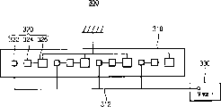
Fig. 6 is the planimetric map that the exemplary light generation unit of the 3rd exemplary embodiment according to the present invention is shown.
With reference to figure 6, photogenerated unit 300 comprises circuit board 310 and light sources 320 or a plurality of light sources 320.
Red light source generates the light that has more than or equal to the wavelength of about 630nm, and green light source generates the light of the wavelength with about 500nm to 630nm, and blue-light source generates the light with the wavelength that is less than or equal to about 465nm.
In Fig. 6, red, green and blue-light source comprises red LED 322, green LED 324 and blue led 326 respectively.Red, green and blue led 322,324 and 326 all can be sheet.
In Fig. 6, redness, green and blue led 322,324 and 326 are arranged to delegation.Alternatively, red, green and blue led 322,324 and 326 can be arranged to different shape, for example, triangle basically.When on the circuit board 310 that a plurality of light sources 320 is installed in as shown in the figure, can sequentially arrange redness, green and blue led 322,324 and 326 with repetitions patterns as shown in the figure, perhaps can other arrange alternatively.
Red, green and blue led 322,324 and 326 is formed on the circuit board 310.Red, green and blue led 322,324 and 326 can be electrically connected to the electrode (not shown) of one patterned on circuit board 310.Red, green and blue led 322,324 and 326 also can be electrically connected to each other.Closing line can be used as redness, green and blue led 322,324 and 326 web members connected to one another.For example, closing line can comprise gold (Au).
Each redness, green and blue led 322,324 and 326 all can comprise lens.The equal diffusion of each lens is respectively from light red, green and that blue led 322,324 and 326 sends, thereby increased the efficient lighting area of red, green and blue led 322,324 and 326.
As shown in Figure 6, photogenerated unit 300 comprises a plurality of light sources 320, and light sources 320 is a line and is arranged on the circuit board 310.Alternatively, light sources 320 can be arranged on the circuit board 310, to form many lines.
Fig. 7 illustrates the synoptic diagram that drives traditional photogenerated unit, and this photogenerated unit comprises the LED with substantially the same efficient lighting area.
With reference to figure 7, traditional photogenerated unit 30 comprises light sources 40 or a plurality of light sources 40.Light sources 40 comprises redness, green and the blue led 42,44 and 46 that is installed on the circuit board 50.Each redness, green and blue led 42,44 and 46 all have substantially the same efficient lighting area.
To impose on redness, green and blue led 42,44 and 46 from the different driving voltage of supply unit 45, with luminous strength ratio corresponding to the ruddiness, green glow and the blue light that are used to form white light with expectation Wavelength distribution.
As shown in Figure 7, with different driving voltage V
R, V
G, and V
BImpose on redness, green and blue led 42,44 and 46 from supply unit 45.For example, driving voltage V
R, V
G, and V
BBe respectively about 1.95V to 2.2V, about 2.8V to 3.7V and about 3.4V to 3.9V.As a result, traditional photogenerated unit 30 generates the white light of the Wavelength distribution with expectation, but needs complicated circuit, to apply different driving voltages to each LED.
Fig. 8 illustrates the synoptic diagram that drives exemplary light generation unit shown in Figure 6.
With reference to figure 8, red, green and blue led 322,324 and 326 is electrically connected to the driving voltage that forms and applies line 312 on circuit board 310.
With driving voltage V
RGB, 1Apply line 312 by driving voltage and be applied to redness, green and blue led 322,324 and 326 from supply unit 330.Red, green and blue led 322,324 and 326 receives driving voltage V
RGB, 1Thereby, generate ruddiness, green glow and blue light respectively.
Usually, when the light-emitting area of LED increased or reduces, along with the voltage that imposes on LED increases or reduces, the luminous intensity of the light that sends from LED also increased or reduces.Thus, when the voltage that imposes on LED changes, also can obtain substantially the same luminous intensity by the light-emitting area that changes LED.
The redness of traditional photogenerated unit 30 shown in Figure 7, green and blue led 42,44 and 46 have substantially the same efficient lighting area.On the contrary, redness, green and the blue led 322,324 and 326 of Fig. 6 and photogenerated unit 300 shown in Figure 8 has first, second and the 3rd efficient lighting area of different size respectively, with the luminous intensity corresponding to the ruddiness, green glow and the blue light that are used to form the white light with expectation Wavelength distribution.
Thus, even only with a driving voltage V
RGB, 1Impose on redness, green and blue led 322,324 and 326, first, second and the 3rd efficient lighting area also can compensate the luminous intensity that reduces, thus the white light that obtains expecting.
Predetermined combinations from the luminous intensity of red, green and ruddiness, green glow and blue light utilization redness, green and blue led 322,324 and 326 that blue led 322,324 and 326 sends forms white light respectively.Therefore, can have the luminous strength ratio of ruddiness, green glow and blue light of the white light of expectation Wavelength distribution, determine first, second and the 3rd efficient lighting area corresponding to formation.Thus, can determine the size of red, green and blue led 322,324 and 326 corresponding to first, second and the 3rd efficient lighting area.
For example, in order to obtain having the white light with the essentially identical Wavelength distribution that distributes by the predetermined wavelength that applies the white light that driving voltage generated of about 2.1V, about 3.3V and about 3.7V to red, green and blue led respectively, can definite redness as described below, first, second and the 3rd light-emitting area of green and blue led 322,324 and 326.
In one exemplary embodiment, the electrical connection that in each light sources 320, is one another in series of red, green and blue led 322,324 and 326, and light sources 320 electrical connection that is connected in parallel to each other.So the electrical connection because light sources 320 is connected in parallel to each other is with essentially identical driving voltage V
RGB, 1Impose on each light sources 320.In other words, with driving voltage V
RGB, 1Impose on the one group of redness, green and the blue led 322,324 and 326 that in a light sources 320, are electrically connected in series.In each redness, green and blue led 322,324 and 326 of essentially identical electric current inflow in a light sources 320.For example, driving voltage V
RGB, 1Be about 3.7V.
According to different inherent characteristics (for example, material), the voltage that imposes on redness, green and blue led 322,324 and 326 can differ from one another.Yet, when voltage is basic identical, first, second and the 3rd light-emitting area can be set into about 2.1: about 3.3: about 3.7.In other words, the light-emitting area of red LED 322 can be less than the light-emitting area of green LED 324, and the light-emitting area of green LED 324 can be less than the light-emitting area of blue led 326.When voltage differed from one another, for example, because different inherent characteristics (for example, material), scalable first, second and the 3rd light-emitting area were with the white light that obtains expecting.
According to present embodiment, first, second and the 3rd efficient lighting area of red, green and blue led 322,324 and 326 set for differ from one another, thereby identical driving voltage is being imposed on redness, green and blue led 322,324 and at 326 o'clock, can obtain having the white light of expectation Wavelength distribution.Because identical driving voltage is imposed on each LED 322,324 and 326,, simplified the circuit structure that is used for driving voltage is imposed on light sources 320 so compare with the circuit structure of photogenerated unit 30 shown in Figure 7.
Fig. 9 is the synoptic diagram that the exemplary light generation unit of driving the 4th exemplary embodiment according to the present invention is shown.
With reference to figure 9, photogenerated unit 400 comprise have redness, the light sources 420 of green and blue led 422,424 and 426.
Electrically connecting as in parallel electrical connection the between red, green and blue led 422,424 and 426, the photogenerated unit 400 of present embodiment is basic identical with the photogenerated unit 300 of Fig. 8.Therefore, omit further describing to it.
Red, green and blue led 422,424 and 426 is electrically connected to the driving voltage that forms and applies line 412 on circuit board 410.
With driving voltage V
RGB, 2Apply line 412 by driving voltage and be applied to redness, green and blue led 422,424 and 426 from supply unit 430.Redness, green and blue led 422,424 and the 426 driving voltage V that receive from supply unit
RGB, 2Thereby, generate ruddiness, green glow and blue light respectively.
As shown in Figure 9, redness, green and blue led 422,424 and 426 in parallel electrical connections, and light sources 420 electrical connection also in parallel.With a driving voltage V
RGB, 2Impose on the light sources 420 that is electrically connected in parallel, and with substantially the same driving voltage V
RGB, 2Impose on each redness, green and blue led 422,424 and 426.
For example, in order to obtain having the white light with the essentially identical Wavelength distribution that distributes by the predetermined wavelength that applies the white light that driving voltage generated of about 2.1V, about 3.3V and about 3.7V to red, green and blue led respectively, and owing to essentially identical driving voltage V
RGB, 2Impose on each redness, green and blue led 422,424 and 426, first, second and the 3rd light-emitting area of red, green and blue led 422,424 and 426 can be set into about 2.1: about 3.3: about 3.7, thus the white light that obtains expecting.In other words, the light-emitting area of red LED 422 can be less than the light-emitting area of green LED 424, and the light-emitting area of green LED 424 can be less than the light-emitting area of blue led 426.
Exemplary embodiment according to Fig. 9, first, second and the 3rd efficient lighting area of red, green and blue led 422,424 and 426 set for differ from one another, thereby a driving voltage is being imposed on redness, green and blue led 422,424 and at 426 o'clock, can obtain having the white light of expectation Wavelength distribution.
In addition, the electrical connection because redness, green and the blue led 422,424 and 426 of photogenerated unit 400 is connected in parallel to each other is so it is basic identical to impose on the driving voltage of redness, green and blue led 422,424 and 426.Thus, when determining efficient lighting area, can omit the additive regulating of efficient lighting area ratio.When different driving voltages being imposed on redness, green and blue led 422,424 and 426, may need additive regulating, with the variation that different inherent characteristic was produced of compensation such as material.
Figure 10 is the decomposition diagram that the exemplary L CD device of the 5th exemplary embodiment according to the present invention is shown.
With reference to Figure 10, LCD device 500 comprises framed (mold frame) 510, light guide plate 520, storage container 530, LCD panel 540, flexible PCB 550 and photogenerated unit 560.
Framed 510 for for example, rectangular shape, and its part is open.Framed 510 for example, comprises plastics.
Light guide plate 520 is arranged in framed 510.The light path guiding of the light that light guide plate 520 will be generated by photogenerated unit 560 is to LCD panel 540.
Light guide plate 520 can comprise transparent material, to reduce light loss.For example, light guide plate 520 comprises having high-intensity polymethylmethacrylate (" PMMA ").
Alternatively, light guide plate 520 can comprise polycarbonate (" PC "), to reduce the thickness of light guide plate 520.Although the intensity of PC is less than the intensity of PMMA, the thermotolerance of PC is stronger than PMMA.
The reflective device (not shown) can be formed, with scattering and reflected light on the lower surface of light guide plate 520.For example, reflective device comprises print pattern and/or relief pattern (embossedpattern).Light is incided light guide plate 520 from photogenerated unit 560, for example, incide the edge of light guide plate 520, and light is by the reflective device scattering and the reflection of light guide plate 520.In light guide plate 520, have greater than the light of the incident angle of predetermined critical upper surface and penetrate to LCD panel 540 from light guide plate 520 by light guide plate 520.
It is framed 510 that storage container 530 is connected to, to cover the bottom of light guide plate 520.For example, storage container 530 comprises intensity greater than framed 510 metal, and can combine by hook with framed 510.
Pass the opening 532 that storage container 530 is formed for holding photogenerated unit 560.
LCD panel 540 is arranged on the top or top of light guide plate 520, comes display image to utilize the light that penetrates from light guide plate 520.
LCD panel 540 comprises lower basal plate 542, upper substrate 544, liquid crystal layer (not shown) and chip for driving 546.Flexible PCB 550 is electrically connected to lower basal plate 542.Upper substrate 544 is relative with lower basal plate 542.Liquid crystal layer is arranged between lower basal plate 542 and the upper substrate 544.Chip for driving 546 is connected to lower basal plate 542.
In response to the control signal that imposes on chip for driving 546 by flexible PCB 550, chip for driving 546 generates the drive signal that is used to drive LCD panel 540.
LCD panel 540 can also comprise the first polarization plates (not shown), is formed on the outside surface of lower basal plate 542; And the second polarization plates (not shown), be formed on the outside surface of upper substrate 544.For example, first polarization plates has first polarization axle, and second polarization plates has second polarization axle vertical substantially with first polarization axle.
Flexible PCB 550 is electrically connected to the sidepiece of lower basal plate 542, and chip for driving 546 is installed on lower basal plate.Flexible printed circuit board 550 for example is electrically connected to lower basal plate 542 by anisotropic conductive film (" ACF ").
Although not shown among Figure 10, on flexible PCB 550, be formed for generating and the element (for example, capacitor and register) of stable control signal.
Because flexible PCB 550 has good flexible, flexible PCB 550 is bent to the back side of storage container 530 from LCD panel 540, and be fixed to the back side of storage container 530.For example, use double sticky tape flexible PCB 550 to be fixed to the back side of storage container 530.
At least one photogenerated unit 560 is electrically connected to flexible PCB 550.Photogenerated unit 560 comprises circuit board, light sources and housing.
Light sources and housing and light sources 120 and housing 130 illustrated in figures 1 and 2 are basic identical.Therefore, omit any further description.
The circuit board of photogenerated unit 560 is corresponding to the partially flexible circuit board 550 of the housing that is used to support photogenerated unit 560 thereon.The circuit structure of the circuit board of photogenerated unit 560 can be basic identical with circuit structure shown in Figure 4.Alternatively, the circuit structure of the circuit board of photogenerated unit 560 can be basic identical with circuit structure shown in Figure 5.Therefore, omit any further description.
When the part of flexible PCB 550 during, omit the independent circuit board of the light sources that is used to drive photogenerated unit 560 as the circuit board of photogenerated unit 560.Thus, LCD device 500 has the structure of simplification, and can reduce the manufacturing cost of LCD device 500.In addition, advantageously, LCD device 500 can be littler and brighter.Alternatively, photogenerated unit 560 can adopt independent circuit board.
On the circuit board of photogenerated unit 560, form driving voltage and apply the line (not shown), to apply driving voltage to light sources.In photogenerated unit 560, circuit board and apply the supply unit (not shown) that the alignment light sources applies driving voltage by driving voltage and form power module.
By crooked flexible PCB 550, photogenerated unit 560 is arranged on a side of the plane of incidence of light guide plate 520.Particularly, when crooked flexible PCB 550, photogenerated unit 560 passes the opening 532 of storage container 530, and with the adjacent setting of the plane of incidence of light guide plate 520.Thus, be formed for the peripheral type backlight assembly of LCD device 500.
The quantity of photogenerated unit 560 is determined in the size that can be by LCD panel 540 and the brightness of expectation.
LCD device 500 comprises the reflector plate 570 that is arranged on below the light guide plate 520 alternatively.The inside of the light reflected back light guide plate 520 that reflector plate 570 will the back side by light guide plate 520 leaks, thus optical efficiency improved.
LCD device 500 can also comprise the optical element 580 of the top or top that is arranged on light guide plate 520.Optical element 580 comprises for example astigmatism plate and at least one optical sheet.Astigmatism plate will penetrate the light scattering of light guide plate 520, to improve the homogeneity of optical brightness.Optical sheet has improved optical characteristics.
Figure 11 is the decomposition diagram that the exemplary L CD device of the 6th exemplary embodiment according to the present invention is shown.
With reference to Figure 11, LCD device 600 comprises a plurality of photogenerateds unit 610, storage container 620 and LCD panel assembly 630.
Each photogenerated unit 610 can be basic identical with the photogenerated unit 300 shown in Fig. 6 and Fig. 8.Thus, omit any further description.Alternatively, photogenerated unit 610 can be basic identical with the photogenerated unit 400 shown in Fig. 9.
Storage container 620 holds photogenerated unit 610.Storage container 620 comprises base plate 622 and sidewall 624.Sidewall 624 extends upward from the marginal portion of base plate 622, to limit spatial accommodation.Storage container 620 for example comprises metal.
Photogenerated unit 610 is arranged on the base plate 622 of storage container 620.Photogenerated unit 610 is separated from each other at interval with rule, and is set parallel to each other basically as shown in figure 11.Because photogenerated unit 610 is provided with and is distributed in the below of LCD panel assembly 630, so LCD device 600 comprises the Staight downward type backlight assembly.
Each photogenerated unit 610 all can comprise a plurality of light sources 614, and wherein light sources is arranged on the circuit board 612 along many lines, rather than as directed, is arranged on a plurality of circuit boards 612.In either case, each light sources 614 includes red LED 614a, green LED 614b and blue led 614c.In addition, circuit board or a plurality of circuit board 612 can be arranged on the outside surface of storage container 620, and light sources 614 can for example be inserted in the storage container 620 by the opening in the base plate 622.
LCD panel assembly 630 comprises LCD panel 632 and driving circuit portion 634.LCD panel 632 utilizes the light that is generated by photogenerated unit 610 to come display image.Driving circuit portion 634 drives LCD panel 632.
LCD panel 632 comprises the first substrate 632a, the second substrate 632b relative with the first substrate 632a and is arranged on liquid crystal layer (not shown) between the first and second substrate 632a and the 632b.
LCD panel 632 is included in first polarization plates (not shown) that forms on the outside surface of the first substrate 632a and the second polarization plates (not shown) that forms on the outside surface of the second substrate 632b.For example, first polarization plates has first polarization axle, and second polarization plates has second polarization axle vertical substantially with first polarization axle.
Driving circuit portion 634 comprises data pcb (" PCB ") 634a, grid PCB634b, data drive circuit film 634c and gate driver circuit film 634d.Data PCB634a provides data-signal to LCD panel 632.Grid PCB 634b provide gating signal to LCD panel 632.Data drive circuit film 634c is connected to LCD panel 632 with data PCB 634a, and gate driver circuit film 634d is connected to LCD panel 632 with grid PCB 634b.
Can utilize band to carry encapsulation (" TCP ") or membrane of flip chip encapsulation (" COF ") formation data drive circuit film 634c and gate driver circuit film 634d.
LCD device 600 can also comprise light guide 640.Light guide 640 is arranged on the top or top of photogenerated unit 610.Light guide 640 separates with photogenerated unit 610.Light guide 640 will be mixed by ruddiness, blue light and the green glow that photogenerated unit 610 generates, to generate white light.Light guide 640 comprises for example PMMA.
LCD device 600 also can comprise the optical element 650 of the top or top that is arranged on light guide 640.Optical element 650 can separate with light guide 640, so that ruddiness, blue light and green glow are mixed with each other.Optical element 650 comprises for example astigmatism plate 652 and at least one optical sheet 654.
The light that astigmatism plate 652 scatterings are penetrated from light guide 640 is to improve the homogeneity of optical brightness.
Optical sheet 654 is arranged on the top or top of astigmatism plate 652, to improve optical characteristics.Optical sheet 654 comprises concentration piece alternatively, and it converges the light by astigmatism plate 652 scatterings, to strengthen front face brightness.Optical sheet 654 comprises scattering sheet alternatively, and its further scattering is by the light of astigmatism plate 652 scatterings.Optical sheet 654 also can comprise multiple, to strengthen desired optical.
According to the present invention, the red light source of photogenerated unit, green light source and blue-light source all have the efficient lighting area that differs from one another, thereby when a driving voltage is imposed on red, green and blue-light source, generate the white light with expectation Wavelength distribution.
In addition, can be with the photogenerated unit package, with the light source as edge light type LCD device, and the photogenerated unit can comprise a plurality of light sources, with the light source as direct illumination type LCD device.
In addition, only when photogenerated unit red, green provides identical voltage with blue-light source, the method that drives the photogenerated unit that is used to generate white light comprises red light source, green light source and the blue-light source that the photogenerated unit that has different efficient lighting areas each other is provided.
Although described exemplary embodiment of the present invention, should be appreciated that the present invention is not limited to these exemplary embodiments, and in the purport and scope of claims, those skilled in the art can carry out multiple change and change.
Claims (29)
1. photogenerated unit comprises:
Light sources comprises a plurality of light sources, and light and each described light source that each described light source all sends different colors from one another all have the efficient lighting area that differs from one another, thereby generates the white light that comprises the mixed light that is sent by described light source; And
Power module is used for a driving voltage is imposed on described light source.
2. photogenerated according to claim 1 unit, wherein, each described light source comprises light emitting diode.
3. photogenerated according to claim 2 unit, wherein, described light emitting diode has sheet.
4. photogenerated according to claim 1 unit, wherein, described light source comprises red light source, green light source and blue-light source.
5. photogenerated according to claim 4 unit, wherein, the efficient lighting area of described blue-light source is greater than the efficient lighting area of described green light source, and the efficient lighting area of described green light source is greater than the efficient lighting area of described red light source.
6. photogenerated according to claim 4 unit, wherein, described red light source generates the light that has more than or equal to about 630nm wavelength, and described green light source generates has the light of about 500nm to about 630nm wavelength, and the generation of described blue-light source has the light that is less than or equal to about 465nm wavelength.
7. photogenerated according to claim 1 unit, wherein, described power module comprises:
Circuit board, having to described light source provides the driving voltage of described driving voltage to apply line; And
Supply unit is used for applying the described light source of alignment and applying described driving voltage by being formed on described driving voltage on the described circuit board.
8. photogenerated according to claim 1 unit, wherein, described circuit board comprises flexible PCB.
9. photogenerated according to claim 1 unit, wherein, described light source is electrically connected in series.
10. photogenerated according to claim 1 unit, wherein, described light source is in parallel to be electrically connected.
11. photogenerated according to claim 1 unit also comprises a plurality of light sources, wherein, the described light source in each light sources is connected in series and described light sources is connected in parallel.
12. photogenerated according to claim 1 unit also comprises housing, is used to hold described light source, wherein, described housing comprises:
Body has the spatial accommodation that holds described light source therein; And
Sub-circuit board is arranged in the described spatial accommodation, being transferred to described light source from the described driving voltage of described power module.
13. photogenerated according to claim 1 unit, wherein, the ratio of described efficient lighting area is corresponding to the luminous strength ratio of the described light that is generated by described light source.
14. a photogenerated unit comprises:
First light source is used to send first light and has first efficient lighting area;
Secondary light source is used to send second light and has second efficient lighting area; And
The 3rd light source is used to send the 3rd light and has the 3rd efficient lighting area,
Wherein, described first efficient lighting area, described second efficient lighting area and described the 3rd efficient lighting area differ from one another, so that described first, second and the 3rd light mix, to generate white light.
15. photogenerated according to claim 14 unit, wherein, described first light source, described secondary light source and described the 3rd light source comprise red light emitting diodes, green LED and blue LED respectively.
16. photogenerated according to claim 14 unit, also comprise power module, be used to drive described first light source, described secondary light source and described the 3rd light source, wherein, described power module applies a driving voltage to described first light source, described secondary light source and described the 3rd light source.
17. photogenerated according to claim 14 unit, wherein, described first light source, described secondary light source and described the 3rd light source are one another in series or in parallel the electrical connection.
18. photogenerated according to claim 14 unit, wherein, the ratio of described first efficient lighting area, described second efficient lighting area and described the 3rd efficient lighting area is corresponding to the luminous strength ratio of described first light, described second light and described the 3rd light.
19. a display device comprises:
The photogenerated unit comprises:
Light sources comprises a plurality of light sources, and light and each described light source that each described light source all sends different colors from one another all have the efficient lighting area that differs from one another, thereby generates the white light that comprises the mixed light that is sent by described light source; And
Power module is used for a driving voltage is imposed on described light source; And
Display panel utilizes the described white light that is generated by described photogenerated unit to come display image.
20. display device according to claim 19, wherein, described light source comprises red light emitting diodes, green LED and blue LED.
21. display device according to claim 19, wherein, described power module comprises:
Circuit board, having to described light source provides the driving voltage of described driving voltage to apply line; And
Supply unit is used for applying the described light source of alignment and applying described driving voltage by being formed on described driving voltage on the described circuit board.
22. display device according to claim 21, wherein, described circuit board comprises flexible PCB, and it is used to drive described display panel.
23. display device according to claim 19, wherein, described light source is one another in series or in parallel the electrical connection.
24. display device according to claim 19, wherein, the ratio of described efficient lighting area is corresponding to the luminous strength ratio of the described light that is generated by described light source.
25. display device according to claim 19 also comprises light guide plate, is arranged on a side of described photogenerated unit, guides to described display panel with the light path of the described white light that will be generated by described photogenerated unit.
26. display device according to claim 19 also comprises light guide, is arranged on the top or top of described photogenerated unit, with the described light of mixing by the generation of described photogenerated unit, thereby provides described white light to described display panel.
27. a display device comprises:
The photogenerated unit comprises:
First light source is used to send first light and has first efficient lighting area;
Secondary light source is used to send second light and has second efficient lighting area; And
The 3rd light source is used to send the 3rd light and has the 3rd efficient lighting area,
Wherein, described first efficient lighting area, described second efficient lighting area and described the 3rd efficient lighting area differ from one another, so that described first light, described second light and the mixing of described the 3rd light, to generate white light; And
Display panel utilizes the described white light that is generated by described photogenerated unit to come display image.
28. a method that drives the photogenerated unit, described photogenerated unit has the light sources that comprises first light source, secondary light source and the 3rd light source, and each light source all sends the light of different colors from one another, and to generate the white light that mixes, described method comprises:
Provide first driving voltage to described first light source with first efficient lighting area;
Provide described first driving voltage to described secondary light source with second efficient lighting area different with described first efficient lighting area; And
Provide described first driving voltage to described the 3rd light source with the 3rd efficient lighting area different with described first and second efficient lighting areas.
29. method according to claim 28, wherein, described first light source, described secondary light source and described the 3rd light source are connected in serial or parallel with each other, and substantially side by side provide described first driving voltage to described first light source, described secondary light source and described the 3rd light source.
Applications Claiming Priority (2)
| Application Number | Priority Date | Filing Date | Title |
|---|---|---|---|
| KR1020050071308 | 2005-08-04 | ||
| KR1020050071308A KR20070016541A (en) | 2005-08-04 | 2005-08-04 | Light generating unit and display device having the same |
Publications (1)
| Publication Number | Publication Date |
|---|---|
| CN1908763A true CN1908763A (en) | 2007-02-07 |
Family
ID=37699913
Family Applications (1)
| Application Number | Title | Priority Date | Filing Date |
|---|---|---|---|
| CNA2006101042100A Pending CN1908763A (en) | 2005-08-04 | 2006-08-01 | Light-generating unit, display device having the same, and method of driving the same |
Country Status (4)
| Country | Link |
|---|---|
| US (1) | US20070029915A1 (en) |
| JP (1) | JP2007043179A (en) |
| KR (1) | KR20070016541A (en) |
| CN (1) | CN1908763A (en) |
Cited By (5)
| Publication number | Priority date | Publication date | Assignee | Title |
|---|---|---|---|---|
| CN103098555A (en) * | 2011-08-26 | 2013-05-08 | 西铁城控股株式会社 | Led illumination device |
| CN103098208A (en) * | 2010-09-16 | 2013-05-08 | 奥斯兰姆奥普托半导体有限责任公司 | Method For Combining LEDs In A Packaging Unit And Packaging Unit Having A Multiplicity Of LEDs |
| CN103363361A (en) * | 2013-08-06 | 2013-10-23 | 敦南科技(无锡)有限公司 | Light source light emitting module |
| CN107479487A (en) * | 2017-09-16 | 2017-12-15 | 南京中高知识产权股份有限公司 | Rimless industrial computer and automatic production line |
| CN110602293A (en) * | 2018-06-12 | 2019-12-20 | Oppo广东移动通信有限公司 | Shell assembly and electronic device |
Families Citing this family (12)
| Publication number | Priority date | Publication date | Assignee | Title |
|---|---|---|---|---|
| US8713109B1 (en) | 2005-04-14 | 2014-04-29 | TJ2Z Patent Licensing and Tech Transfer, LLC | Method and apparatus for storing email messages |
| KR100765240B1 (en) * | 2006-09-30 | 2007-10-09 | 서울옵토디바이스주식회사 | Light emitting diode package having light emitting cell with different size and light emitting device thereof |
| KR101284041B1 (en) * | 2006-11-03 | 2013-07-09 | 삼성디스플레이 주식회사 | Light emitting module |
| WO2011125885A1 (en) * | 2010-03-31 | 2011-10-13 | インテックス株式会社 | Light-source device |
| US8550647B2 (en) * | 2010-06-15 | 2013-10-08 | Micron Technology, Inc. | Solid state lighting device with different illumination parameters at different regions of an emitter array |
| CA2814119C (en) | 2010-10-12 | 2017-01-17 | Alliance For Sustainable Energy, Llc | High bandgap iii-v alloys for high efficiency optoelectronics |
| TWI456143B (en) * | 2012-04-26 | 2014-10-11 | 新世紀光電股份有限公司 | Light emitting module |
| US10788678B2 (en) | 2013-05-17 | 2020-09-29 | Excelitas Canada, Inc. | High brightness solid state illumination system for fluorescence imaging and analysis |
| CN104981647A (en) | 2013-09-23 | 2015-10-14 | Glo公司 | Integrated back light unit |
| US10211185B2 (en) | 2014-10-31 | 2019-02-19 | Bridgelux Inc. | High efficiency chip-on-board light-emitting diode |
| CN104538391B (en) * | 2014-12-31 | 2018-01-26 | 深圳市华星光电技术有限公司 | White light LEDs module |
| JP6583247B2 (en) * | 2016-12-21 | 2019-10-02 | 日亜化学工業株式会社 | Light emitting device |
Family Cites Families (6)
| Publication number | Priority date | Publication date | Assignee | Title |
|---|---|---|---|---|
| US5808592A (en) * | 1994-04-28 | 1998-09-15 | Toyoda Gosei Co., Ltd. | Integrated light-emitting diode lamp and method of producing the same |
| US6095661A (en) * | 1998-03-19 | 2000-08-01 | Ppt Vision, Inc. | Method and apparatus for an L.E.D. flashlight |
| US6357893B1 (en) * | 2000-03-15 | 2002-03-19 | Richard S. Belliveau | Lighting devices using a plurality of light sources |
| US6995355B2 (en) * | 2003-06-23 | 2006-02-07 | Advanced Optical Technologies, Llc | Optical integrating chamber lighting using multiple color sources |
| US7667766B2 (en) * | 2003-12-18 | 2010-02-23 | Avago Technologies Ecbu Ip (Singapore) Pte. Ltd. | Adjustable spectrum flash lighting for image acquisition |
| US7438442B2 (en) * | 2005-10-12 | 2008-10-21 | Lg Display Co., Ltd. | Light emitting package, backlight unit and liquid crystal display device including the same |
-
2005
- 2005-08-04 KR KR1020050071308A patent/KR20070016541A/en not_active Application Discontinuation
-
2006
- 2006-08-01 CN CNA2006101042100A patent/CN1908763A/en active Pending
- 2006-08-03 US US11/498,516 patent/US20070029915A1/en not_active Abandoned
- 2006-08-04 JP JP2006212768A patent/JP2007043179A/en not_active Withdrawn
Cited By (7)
| Publication number | Priority date | Publication date | Assignee | Title |
|---|---|---|---|---|
| CN103098208A (en) * | 2010-09-16 | 2013-05-08 | 奥斯兰姆奥普托半导体有限责任公司 | Method For Combining LEDs In A Packaging Unit And Packaging Unit Having A Multiplicity Of LEDs |
| CN103098208B (en) * | 2010-09-16 | 2017-03-29 | 奥斯兰姆奥普托半导体有限责任公司 | The method and the encapsulation unit with multiple LED of LED are assembled in encapsulation unit |
| CN103098555A (en) * | 2011-08-26 | 2013-05-08 | 西铁城控股株式会社 | Led illumination device |
| CN103098555B (en) * | 2011-08-26 | 2014-12-03 | 西铁城控股株式会社 | LED illumination device |
| CN103363361A (en) * | 2013-08-06 | 2013-10-23 | 敦南科技(无锡)有限公司 | Light source light emitting module |
| CN107479487A (en) * | 2017-09-16 | 2017-12-15 | 南京中高知识产权股份有限公司 | Rimless industrial computer and automatic production line |
| CN110602293A (en) * | 2018-06-12 | 2019-12-20 | Oppo广东移动通信有限公司 | Shell assembly and electronic device |
Also Published As
| Publication number | Publication date |
|---|---|
| JP2007043179A (en) | 2007-02-15 |
| KR20070016541A (en) | 2007-02-08 |
| US20070029915A1 (en) | 2007-02-08 |
Similar Documents
| Publication | Publication Date | Title |
|---|---|---|
| CN1908763A (en) | Light-generating unit, display device having the same, and method of driving the same | |
| CN1258113C (en) | Illuminating device, liquid crystal device and electronic equipment | |
| CN1639619A (en) | Optical member, backlight assembly and liquid crystal display device using the same | |
| CN1854853A (en) | Display device | |
| CN1991520A (en) | Light-emitting module, method of manufacturing the same and display device having the same | |
| CN1731254A (en) | The backlight that is used for display device | |
| CN1196305C (en) | Illuminator and portable information apparatus with the same illuminator | |
| CN1975534A (en) | Apparatus for driving of back light, back light assembly and liquid crystal display device and method of the driving | |
| CN101055375A (en) | Backlight assembly and display device having the same | |
| CN1892364A (en) | Light emitting diode module, backlight assembly and display device provided with the same | |
| CN1897073A (en) | Light source apparatus and display apparatus | |
| CN1696788A (en) | LCD device | |
| CN1763603A (en) | Light emitting diode and its lens of employing | |
| CN1932593A (en) | Light source device, display device, terminal device, light source unit, and method for driving light source device | |
| CN1800942A (en) | Light guide plate, back light assembly having the same and display apparatus having the same | |
| CN1273641A (en) | Light source and display device | |
| CN1462354A (en) | Illumination system and display device | |
| CN1811890A (en) | Display panel assembly and display apparatus having the same | |
| CN1851500A (en) | Optical lens, optical package having the same, backlight assembly having the same and display device having the same | |
| CN1461965A (en) | Back-light assembly and liquid crystal display with the assembly | |
| CN1758116A (en) | White light generating unit, backlight assembly and liquid crystal indicator | |
| CN1904650A (en) | Optical lens, optical assembly, backlight assembly, display device, and method thereof | |
| CN1815333A (en) | Back light assembly and display device within this | |
| CN1831613A (en) | Lighting device, electro-optical device and electronic apparatus | |
| CN1920625A (en) | Display apparatus and method of manufacturing the same |
Legal Events
| Date | Code | Title | Description |
|---|---|---|---|
| C06 | Publication | ||
| PB01 | Publication | ||
| C10 | Entry into substantive examination | ||
| SE01 | Entry into force of request for substantive examination | ||
| C02 | Deemed withdrawal of patent application after publication (patent law 2001) | ||
| WD01 | Invention patent application deemed withdrawn after publication |
Open date: 20070207 |