CN1754319A - Sub-banded ultra-wideband communication system - Google Patents
Sub-banded ultra-wideband communication system Download PDFInfo
- Publication number
- CN1754319A CN1754319A CNA038107066A CN03810706A CN1754319A CN 1754319 A CN1754319 A CN 1754319A CN A038107066 A CNA038107066 A CN A038107066A CN 03810706 A CN03810706 A CN 03810706A CN 1754319 A CN1754319 A CN 1754319A
- Authority
- CN
- China
- Prior art keywords
- sub
- waveform
- wideband waveform
- banded ultra
- ultra
- Prior art date
- Legal status (The legal status is an assumption and is not a legal conclusion. Google has not performed a legal analysis and makes no representation as to the accuracy of the status listed.)
- Granted
Links
Images


Classifications
-
- H—ELECTRICITY
- H04—ELECTRIC COMMUNICATION TECHNIQUE
- H04B—TRANSMISSION
- H04B1/00—Details of transmission systems, not covered by a single one of groups H04B3/00 - H04B13/00; Details of transmission systems not characterised by the medium used for transmission
- H04B1/69—Spread spectrum techniques
- H04B1/7163—Spread spectrum techniques using impulse radio
- H04B1/71632—Signal aspects
-
- H—ELECTRICITY
- H04—ELECTRIC COMMUNICATION TECHNIQUE
- H04B—TRANSMISSION
- H04B1/00—Details of transmission systems, not covered by a single one of groups H04B3/00 - H04B13/00; Details of transmission systems not characterised by the medium used for transmission
- H04B1/69—Spread spectrum techniques
- H04B1/692—Hybrid techniques using combinations of two or more spread spectrum techniques
-
- H—ELECTRICITY
- H04—ELECTRIC COMMUNICATION TECHNIQUE
- H04B—TRANSMISSION
- H04B1/00—Details of transmission systems, not covered by a single one of groups H04B3/00 - H04B13/00; Details of transmission systems not characterised by the medium used for transmission
- H04B1/69—Spread spectrum techniques
- H04B1/7163—Spread spectrum techniques using impulse radio
-
- H—ELECTRICITY
- H04—ELECTRIC COMMUNICATION TECHNIQUE
- H04L—TRANSMISSION OF DIGITAL INFORMATION, e.g. TELEGRAPHIC COMMUNICATION
- H04L27/00—Modulated-carrier systems
- H04L27/26—Systems using multi-frequency codes
- H04L27/2601—Multicarrier modulation systems
-
- H—ELECTRICITY
- H04—ELECTRIC COMMUNICATION TECHNIQUE
- H04B—TRANSMISSION
- H04B1/00—Details of transmission systems, not covered by a single one of groups H04B3/00 - H04B13/00; Details of transmission systems not characterised by the medium used for transmission
- H04B1/69—Spread spectrum techniques
- H04B1/7163—Spread spectrum techniques using impulse radio
- H04B1/719—Interference-related aspects
Landscapes
- Engineering & Computer Science (AREA)
- Computer Networks & Wireless Communication (AREA)
- Signal Processing (AREA)
- Transmitters (AREA)
- Mobile Radio Communication Systems (AREA)
- Measurement And Recording Of Electrical Phenomena And Electrical Characteristics Of The Living Body (AREA)
- Input Circuits Of Receivers And Coupling Of Receivers And Audio Equipment (AREA)
- Mechanical Means For Catching Fish (AREA)
- Reduction Or Emphasis Of Bandwidth Of Signals (AREA)
- Details Of Aerials (AREA)
Abstract
Description
附图说明Description of drawings
通过参考附图,本领域的技术人员可以更好的理解本发明的众多优点,其中:By referring to the accompanying drawings, those skilled in the art can better understand numerous advantages of the present invention, wherein:
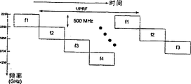
图1是根据本发明实施例的子带化超宽带(sub-banded ultra-wideband,SB-UWB)系统的时域和频域表示。FIG. 1 is a representation in time domain and frequency domain of a sub-banded ultra-wideband (sub-banded ultra-wideband, SB-UWB) system according to an embodiment of the present invention.
图2是根据本发明实施例的基于FFT的发射机系统图。FIG. 2 is a system diagram of an FFT-based transmitter according to an embodiment of the present invention.
图3是根据本发明实施例的基于FFT的接收机系统图。FIG. 3 is a system diagram of an FFT-based receiver according to an embodiment of the present invention.
图4是根据本发明实施例的子带化UWB脉冲发生器的图。FIG. 4 is a diagram of a subbanded UWB pulse generator according to an embodiment of the present invention.
图5是根据本发明实施例的利用信道化技术的UWB发射机图。FIG. 5 is a diagram of a UWB transmitter utilizing channelization techniques according to an embodiment of the present invention.
图6是根据本发明实施例的用于多载波脉冲产生系统的匹配滤波接收机图。FIG. 6 is a diagram of a matched filter receiver for a multi-carrier pulse generation system according to an embodiment of the present invention.
图7是根据本发明实施例的基于开关滤波器的发射机图。Figure 7 is a diagram of a switched filter based transmitter according to an embodiment of the present invention.
图8是根据本发明实施例的子带化超宽带波形输出的时域表示图。FIG. 8 is a time-domain representation of a subbanded UWB waveform output according to an embodiment of the present invention.
图9是根据本发明实施例的子带化超宽带波形输出的频谱图。FIG. 9 is a spectrum diagram of a subbanded UWB waveform output according to an embodiment of the present invention.
图10是根据本发明实施例的多载波UWB信号的时间-频率平面表示图。FIG. 10 is a time-frequency plane representation of a multi-carrier UWB signal according to an embodiment of the present invention.
图11是根据本发明实施例的对多载波UWB系统采用亚采样的直接转换接收机图。FIG. 11 is a diagram of a direct conversion receiver using sub-sampling for a multi-carrier UWB system according to an embodiment of the present invention.
具体实施方式Detailed ways
现在参考图1,将要讨论根据本发明实施例的子带化超宽带(SB-UWB)系统的时域和频域表示。超宽带通信可以被定义为同时在一段频率范围的全部或一部分上传送无线信号,但是本发明的范围并不局限于此。子带化UWB信号可以包括用于UWB信号的频率范围内的至少一个或者多个频率范围,但是本发明的范围并不局限于此。如图1所示,在坐标图100中图示了基于示例性脉冲的正交频分复用(OFDM)方案,在坐标图102中图示了基于示例性脉冲的正交频分和时分复用(OF/TDM)方案,并且在坐标图104中图示了级联OFDM波形的示例性频率图。在图1所示的示例中,使用具有例如500MHz的带宽和可以在3和6GHz之间变化的中心频率的脉冲可以产生六个脉冲无线电超宽带(IR-UWB)波形,但是本发明的范围并不局限于此。Referring now to FIG. 1 , time domain and frequency domain representations of a subbanded ultra wideband (SB-UWB) system according to an embodiment of the present invention will be discussed. Ultra-wideband communication may be defined as the simultaneous transmission of wireless signals over all or a portion of a frequency range, although the scope of the invention is not limited thereto. A subbanded UWB signal may include at least one or more frequency ranges within the frequency range used for UWB signals, although the scope of the invention is not limited thereto. As shown in FIG. 1 , an exemplary pulse-based Orthogonal Frequency Division Multiplexing (OFDM) scheme is illustrated in
如图1所示,与传统的OFDM系统不同,SB-UWB实现方式可以提供在时间和频率上分隔波形的能力。例如,随着脉冲波形持续时间的增加,随着子带带宽的减小,传输波形可以在时间上连续并且可以开始与OFDM波形类似。子带还可以包括每比特多个脉冲的附加扩展,以得到直接序列SB-UWB(DS-SB-UWB)系统,但是本发明的范围并不局限于此。As shown in Figure 1, unlike conventional OFDM systems, SB-UWB implementations can provide the ability to separate waveforms in time and frequency. For example, as the duration of the pulse waveform increases, as the subband bandwidth decreases, the transmission waveform can be continuous in time and can start to resemble an OFDM waveform. The sub-bands may also include additional extensions of multiple pulses per bit to obtain a Direct Sequence SB-UWB (DS-SB-UWB) system, but the scope of the invention is not limited thereto.
利用SB-UWB波形可以相对直接地将波形覆盖在窄带干扰之上。这样,在本发明的第一实施例中,通过不利用其中存在强烈窄带干扰的任何频带可以提供覆盖,但是本发明的范围并不局限于此。或者,可以使用多数频带或所有频带,但是要依照干扰强度的比例削弱那些经常受到干扰的频带,从而导致频域内的“注水”(water-filling)效果,但是本发明的范围并不局限于此。相似地,通过在发射机和接收机两者处都采用陷波滤波器(notch filter)可以在分散的窄带信号上覆盖足够宽带的单个载波波形。发射机的陷波滤波器可以保护窄带波形,而接收机的陷波滤波器可以保护所需信号。SB-UWB信号设计不使用陷波滤波器就可以允许同样类型的干扰耐受性,但是本发明的范围并不局限于此。在图2和图3中分别示出了基于FFT/IFFT实现方式的子带发射机200和接收机300。Utilizing the SB-UWB waveform can relatively directly cover the waveform on the narrowband interference. Thus, in the first embodiment of the present invention, coverage can be provided by not utilizing any frequency band in which strong narrowband interference exists, but the scope of the present invention is not limited thereto. Alternatively, most or all frequency bands may be used, but those frequency bands that are frequently interfered with are attenuated in proportion to the interference strength, resulting in a "water-filling" effect in the frequency domain, but the scope of the invention is not limited thereto . Similarly, a single carrier waveform of sufficient bandwidth can be overlaid on scattered narrowband signals by employing notch filters at both the transmitter and receiver. A notch filter in the transmitter protects narrowband waveforms, while a notch filter in the receiver protects the desired signal. The SB-UWB signal design would allow the same type of interference immunity without the use of a notch filter, although the scope of the invention is not so limited. A
在另一个实施例中,SB-UWB体系结构还可以和其他的时域扩展技术组合起来,这些时域扩展技术包括在每个子带信道上使用的跳时(TH-SB-UWB)或者直接序列扩展(DS-SB-UWB),但是本发明的范围并不局限于此。对于给定的多通路信道概况(profile)和干扰环境,为了最优化系统的总吞吐量,可能存在对于子带数量、每个子带的带宽以及每个子带需要的时域扩展的最佳配置。在本发明的一个实施例中,如果对子带数量的限制降到一个,那么系统就可以与典型的IR-UWB系统相似,但是本发明的范围并不局限于此。In another embodiment, the SB-UWB architecture can also be combined with other time-domain extension techniques including time-hopping (TH-SB-UWB) or direct-sequence extension (DS-SB-UWB), but the scope of the present invention is not limited thereto. For a given multi-path channel profile and interference environment, in order to optimize the overall throughput of the system, there may be an optimal configuration for the number of sub-bands, the bandwidth of each sub-band, and the time-domain extension required for each sub-band. In one embodiment of the invention, if the limit on the number of subbands is reduced to one, then the system can be similar to a typical IR-UWB system, but the scope of the invention is not limited thereto.
现在参考图2和图3,将讨论根据本发明的一个实施例的基于快速傅利叶变换(FFT)的发射机系统和基于FFT的接收机系统的图。图2所示的示例性发射机200示出了基于FFT/IFFT的SB-UWB发射机的实现方式,而图3所示的示例性接收机300示出了基于FFT/IFFT的SB-UWB接收机的实现方式。基带子带(0到WGHz,其中W是传输波形所需的RF带宽)可以通过N点IFFT并且在并行到串行转换器(P/S)之后产生,但是本发明的范围并不局限于此。在具体的实施例中,基带带宽可以在2GHz的数量级上或者更高,其中IFFT操作的速度可能是一个限制因素,但是本发明的范围并不局限于此。在一个实施例中,虽然N-pt的IFFT操作可以使用任意合理的N值,但是可以利用4-pt的IFFT块使速度最大化。这样的实现方式允许每个载波块产生4个子带。然后,载波块可以被上变频到所需的RF频率,但是本发明的范围并不局限于此。如下面所讨论的,可以通过一种或者多种方式来安排这样的实现方法,以实现SB-UWB系统。Referring now to Figures 2 and 3, diagrams of a Fast Fourier Transform (FFT) based transmitter system and an FFT based receiver system according to one embodiment of the present invention will be discussed. The
在一个实施例中,可以利用OFDM波形来实现SB-UWB系统。这样的实现方式可以基于所有子带的同时传输,所述子带的同时传输可以利用一个单独的载波块或者多个载波块来完成,以满足所需的RF频率,但是本发明的范围并不局限于此。In one embodiment, an SB-UWB system can be implemented using OFDM waveforms. Such an implementation may be based on simultaneous transmission of all subbands, which may be accomplished using a single carrier block or multiple carrier blocks to meet the required RF frequency, but the scope of the present invention is not limited to this.
在另一实施例中,可以利用线性调频(chirped)波形来实现SB-UWB系统。在这样的实施例中,可以在不同的时刻传送子带波形,以提供传输比特之间的时间多样性和频率多样性。该实现方式有助于减小接收机对频率偏移错配的敏感性,以减小或者最小化相邻信道干扰,但是本发明的范围并不局限于此。In another embodiment, the SB-UWB system can be implemented using a chirped waveform. In such an embodiment, the sub-band waveforms may be transmitted at different time instants to provide time diversity and frequency diversity between transmitted bits. This implementation helps reduce receiver susceptibility to frequency offset mismatches to reduce or minimize adjacent channel interference, although the scope of the invention is not limited thereto.
在另一实施例中,可以利用频移键控(FSK)波形来实现SB-UWB系统。在这样的实施例中,可以使用编码数据比特来选择多个频率之一用于信道传输,而不是将数据分别调制在载波上并且同时传送数据。这样的方法可以利用正交调制,并且通过一次传输一种载波,可以减少传输的“峰值对平均”功率比,并且因而减少对RF组件的线性度的要求,但是本发明的范围并不局限于此。In another embodiment, the SB-UWB system can be implemented using Frequency Shift Keying (FSK) waveforms. In such an embodiment, encoded data bits may be used to select one of multiple frequencies for channel transmission, rather than separately modulating the data on a carrier and transmitting the data simultaneously. Such an approach may utilize quadrature modulation, and by transmitting one carrier at a time, the "peak-to-average" power ratio of the transmission may be reduced, and thus reduce the linearity requirements of the RF components, but the scope of the invention is not limited to this.
在另一实施例中,可以利用跳频(FH)波形来实现SB-UWB系统。在这样的实施例中,可以使用例如4比特的伪随机码来选择将承载数据的子带,但是本发明的范围并不局限于此。In another embodiment, a SB-UWB system can be implemented using frequency hopping (FH) waveforms. In such an embodiment, a pseudo-random code, eg, 4 bits, may be used to select the subbands that will carry data, although the scope of the invention is not limited thereto.
在图2和图3的发射机和接收机体系结构的一个实施例中,例如,UWB OFDM信号的占空比一般小于10%,这与占空比一般是100%的窄带OFDM信号形成了对照。较低的占空比使子带不必使用均衡化就可以具有比窄带情况宽得多的带宽。用于发射机200和接收机300的FFT体系结构可以允许在数字FFT中提供多个模拟振荡器的复杂情况,但是本发明的范围并不局限于此。In one embodiment of the transmitter and receiver architectures of Figures 2 and 3, for example, UWB OFDM signals typically have a duty cycle of less than 10%, in contrast to narrowband OFDM signals, which typically have a 100% duty cycle . The lower duty cycle allows the subband to have a much wider bandwidth than the narrowband case without having to use equalization. The FFT architecture used for
现在参考图4,将讨论根据本发明实施例的子带化UWB脉冲发生器的图。如图4的示例性脉冲发生器400所示,并行地利用两个或者多个正弦波发生器来产生UWB波形,但是本发明的范围并不局限于此。在另一个实施例中,脉冲发生器400可以被扩展到包括多个相位,例如四相相移键控QPSK,但是本发明的范围并不局限于此。在一个具体的实施例中,可以使用两个或多个并联的门控功能402,其中一个门控功能可以是另一个门控功能的延迟形式,但是本发明的范围并不局限于此。或者,载波的相位可以被调制,例如使用相移键控(PSK)系统来调制,但是本发明的范围并不局限于此。通过提供对不同频率和时间窗的选择,可以对脉冲发生器400的信号设计提供更大的灵活性。在一个实施例中,信号能量可以被更加均匀的分散到频带中,因为,在功率谱密度(PSD)受限的环境中,例如在可以通过规则设定PSD界限的环境中,可能会希望频谱尽可能的平坦,但是本发明的范围并不局限于此。在另一个实施例中,为了根据需求裁剪频谱,可以调整各个窗的宽度,但是本发明的范围并不局限于此。Referring now to FIG. 4, a diagram of a subbanded UWB pulse generator according to an embodiment of the present invention will be discussed. As shown in the
现在参考图5,将要讨论根据本发明实施例的利用信道化技术的UWB发射机图。在图5所示的示例中,在坐标图500示出了波形的频率图,其中连同可能出现窄带干扰源的频带一起,示出了具有两个频率f1和f2的系统。在这个实施例中,为了在频谱中的所需频带形成陷波502,可以调整两个带宽B1和B2。接着如图5所示,通过使用脉冲发生器504来改变用于振荡器508的时间门控窗506的宽度,可以控制带宽B1和B2。在接收端,可以基于频率和时间窗宽度信息为脉冲设立匹配滤波器,但是本发明的范围并不局限于此。Referring now to FIG. 5, a diagram of a UWB transmitter utilizing channelization techniques according to an embodiment of the present invention will be discussed. In the example shown in FIG. 5 , a frequency diagram of a waveform is shown on a
如图6所示,将要讨论根据本发明实施例的用于多载波脉冲产生系统的匹配滤波接收机图。图6示出了另一个脉冲发生器600。对于示例性脉冲发生器600,单独的副载波可具有与其所在信道的脉冲相匹配的滤波器,但是本发明的范围并不局限于此。或者,可以使用振荡器602来与传送信号同步。使用振荡器602可以减小同步的复杂性,因为可以将窄带脉冲对准到振荡器最近的周期,而不用将两个窄带脉冲彼此对准,但是本发明的范围并不局限于此。As shown in FIG. 6, a matched filter receiver diagram for a multi-carrier pulse generation system according to an embodiment of the present invention will be discussed. FIG. 6 shows another
在利用这样信令脉冲的系统中,接入点可以进行干扰测量和评估,以及为不同的频率确定时间窗的宽度,从而产生适当的谱形状。该信息可以在公共广播信道上被传送到一个或多个节点,该信道可能具有多个副载波频率中的一个频率,例如f1。然后,接收机可以通过为调谐在不同的副载波频率上的本地振荡器设置适当的时间窗宽度来建立副载波接收机匹配滤波器,并且可以接收全部带宽的UWB信号传输,但是本发明的范围并不局限于此。In a system utilizing such signaling pulses, the access point can perform interference measurements and assessments, as well as determine the width of the time window for different frequencies, resulting in an appropriate spectral shape. This information may be communicated to one or more nodes on a common broadcast channel, which may have one of several subcarrier frequencies, eg fl. The receiver can then set up a subcarrier receiver matched filter by setting an appropriate time window width for a local oscillator tuned on a different subcarrier frequency, and can receive UWB signal transmissions of the full bandwidth, but the scope of the present invention It is not limited to this.
现在参考图7,将讨论根据本发明实施例的基于开关滤波器(switchedfilter)的发射机图。图7中所示的发射机700可以是基于一次传送一个子带的规则来产生SB-UWB波形的另一个示例。在这样的实施例中,数据702可以调制单一的宽带脉冲发生器704,并且可以用RF开关706来选择通过无线传递传送哪一个子带,但是本发明的范围并不局限于此。在该实施例中,RF开关706可以工作在脉冲重复率下,该速率可以是所支持的所需数据率的函数。图7还示出了可选的上变频器708,在实施例中,可以用该上变频器708将子带从IF频率上变频到所需的RF频率,在该实施例中可能需要在较低的频带上设计子带滤波器710,但是本发明的范围并不局限于此。Referring now to FIG. 7, a diagram of a switched filter based transmitter according to an embodiment of the present invention will be discussed. The
现在参考图8,将要讨论根据本发明实施例的子带化超宽带波形输出的时域表示图。还要参考图9,将要讨论根据本发明实施例的子带化超宽带波形输出的频谱图。对于图8的波形输出800和图9的传送波形谱900,可以利用亚采样方案,该方案允许对单独的子带信号的有效采样和处理。在示例性实施例中,如图8所示,并且也如图10的示例所示出的,所考虑的多载波UWB系统可以具有2GHz的总信号带宽,并且采用顺序传送的带宽500MHz的四个副载波,但是本发明的范围并不局限于此。因为在任意给定时刻,可能传送其中一个副载波,所以在示例性实施例中,可以在500MHz的有效速率下利用如图11所示的复数模数转换器(ADC)1102,其可以对副载波中的任意一个进行采样,但是本发明的范围并不局限于此。图10示出了根据本发明实施例的多载波UWB信号的示例性时间-频率平面表示图。Referring now to FIG. 8, a time domain representation of a subbanded UWB waveform output according to an embodiment of the present invention will be discussed. Referring also to FIG. 9 , a spectrogram of a subbanded UWB waveform output according to an embodiment of the present invention will be discussed. For the
现在参考图11,将要讨论根据本发明实施例的对多载波UWB系统采用亚采样的直接转换接收机图。可以首先采用直接下变频零中频(IF)接收机体系结构1100将总的UWB信号带宽下变频,使得副载波频率,或者最低频率可以被下变频到如图11中的接收机体系结构1100所示的零IF,并且使用工作在500MHz速率的两个ADC来采样I和Q信号,但是本发明的范围并不局限于此。在下变频器之后的低通滤波器(LPF)1104可以足够宽以容纳所有的子带,仅过滤出混频产物,或者可替换地,该LPF可以是子带选择滤波器,它可以是在特定时刻只包含一个子带的带通滤波器。这种可选择的带通滤波器可以根据传送顺序切换到相应子带。当在第一子带中传送第一UWB脉冲时,复数ADC可以捕获传输脉冲的样本。后来的脉冲可以根据预定的顺序在其它副载波频率上传送。这些脉冲和副载波可以通过500MHz的复数模数转换器(ADC)进行亚采样,但是本发明的范围并不局限于此。Referring now to FIG. 11 , a diagram of a direct conversion receiver employing subsampling for a multi-carrier UWB system according to an embodiment of the present invention will be discussed. The total UWB signal bandwidth may first be downconverted using a direct downconversion zero intermediate frequency (IF)
或者,图11示出的接收机可以包括固定的LPF 1104,其具有和每个子带的RF带宽大致相等的带宽,但是对于不同的实现方式,该带宽会依赖于ADC转换器1102的输入带宽和采样率而有所不同,其中到混频器输入端处的参考频率可以及时改变,以匹配传输子带的顺序。对于一次传送一个子带的情况,如图8所示,在混频器输入端处的参考波形基本上看起来就像传送波形的复制品,并且在接收机处,该参考波形可以通过与用在其他无线通信系统中相似的训练过程被同步,但是本发明的范围并不局限于此。Alternatively, the receiver shown in FIG. 11 may include a fixed LPF 1104 with a bandwidth approximately equal to the RF bandwidth of each subband, but for different implementations this bandwidth will depend on the input bandwidth of the
虽然本发明已经被描述的相当具体,但是应该认识到,不脱离本发明的精神和范围,本领域的技术人员可以改变其中的元件。相信通过前面的描述将能够理解本发明的子带化超宽带通信系统以及该系统附带的优点,并且很清楚,可以对其中的形式、结构及其组件安排进行各种改变,而不会脱离本发明的范围和精神或者不牺牲本发明的所有实质性优点,并且由于此前描述的形式仅仅是本发明的说明性实施例,也不会提供另外的实质性改变。权利要求书意在涵盖并包括这些改变。While the invention has been described with considerable particularity, it will be appreciated that elements thereof may be changed by those skilled in the art without departing from the spirit and scope of the invention. It is believed that the subbandized ultra-wideband communication system of the present invention and the accompanying advantages of the system can be understood through the foregoing description, and it is clear that various changes can be made to the form, structure and component arrangement thereof without departing from the present invention. The scope and spirit of the invention may be achieved without sacrificing all of the essential advantages of the present invention, and since the form described heretofore is merely an illustrative embodiment of the invention, no other substantial change may be provided. The claims are intended to cover and embrace such changes.
Claims (38)
Applications Claiming Priority (3)
| Application Number | Priority Date | Filing Date | Title |
|---|---|---|---|
| US10/241,889 US7532564B2 (en) | 2002-09-11 | 2002-09-11 | Sub-banded ultra-wideband communications systems |
| US10/241,889 | 2002-09-11 | ||
| PCT/US2003/028085 WO2004025853A2 (en) | 2002-09-11 | 2003-09-05 | Sub-banded ultra-wideband communication system |
Publications (2)
| Publication Number | Publication Date |
|---|---|
| CN1754319A true CN1754319A (en) | 2006-03-29 |
| CN100596031C CN100596031C (en) | 2010-03-24 |
Family
ID=31991278
Family Applications (1)
| Application Number | Title | Priority Date | Filing Date |
|---|---|---|---|
| CN03810706A Expired - Fee Related CN100596031C (en) | 2002-09-11 | 2003-09-05 | Sub-band UWB Communication System and Method |
Country Status (8)
| Country | Link |
|---|---|
| US (1) | US7532564B2 (en) |
| EP (1) | EP1537679B1 (en) |
| CN (1) | CN100596031C (en) |
| AT (1) | ATE434867T1 (en) |
| AU (1) | AU2003278773A1 (en) |
| DE (1) | DE60328106D1 (en) |
| TW (1) | TWI261430B (en) |
| WO (1) | WO2004025853A2 (en) |
Cited By (3)
| Publication number | Priority date | Publication date | Assignee | Title |
|---|---|---|---|---|
| CN101911626A (en) * | 2007-12-31 | 2010-12-08 | 英特尔公司 | Hopping ultra-wideband wireless |
| CN102714520A (en) * | 2010-01-15 | 2012-10-03 | 索尤若驱动有限及两合公司 | Method for data transfer and data transfer system |
| CN106031047A (en) * | 2014-03-21 | 2016-10-12 | 华为技术有限公司 | Signal processing method, device and system |
Families Citing this family (30)
| Publication number | Priority date | Publication date | Assignee | Title |
|---|---|---|---|---|
| US7532564B2 (en) | 2002-09-11 | 2009-05-12 | Intel Corporation | Sub-banded ultra-wideband communications systems |
| US7292620B2 (en) * | 2002-12-31 | 2007-11-06 | Intel Corporation | Method and apparatus to generate a clock-based transmission |
| US7756002B2 (en) * | 2003-01-30 | 2010-07-13 | Texas Instruments Incorporated | Time-frequency interleaved orthogonal frequency division multiplexing ultra wide band physical layer |
| WO2004073195A1 (en) * | 2003-02-14 | 2004-08-26 | Koninklijke Philips Electronics N.V. | Variable sign/phase and inter-pulse time modulated multi-band uwb communication system |
| WO2004077775A1 (en) * | 2003-02-25 | 2004-09-10 | Yokohama Tlo Company, Ltd. | Pulse waveform producing method |
| US7242707B1 (en) * | 2003-07-22 | 2007-07-10 | Miao George J | Multiband ultra wideband communications |
| KR100498049B1 (en) * | 2003-08-12 | 2005-07-01 | 삼성전자주식회사 | Receiving apparatus for muti-band UWB communication system and method of using the same |
| EP1723728B1 (en) * | 2004-02-19 | 2019-10-16 | Texas Instruments Incorporated | Scalable, cooperative, wireless networking for mobile connectivity |
| US7415245B2 (en) * | 2004-03-31 | 2008-08-19 | Intel Corporation | Pulse shaping signals for ultrawideband communication |
| KR100608991B1 (en) * | 2004-04-08 | 2006-08-03 | 곽경섭 | Low Interference Ultra-Wideband Wireless Communication System Using Spreading Code with Low Correlation or Zero Correlation, and Its Communication Processing Method |
| WO2005099293A1 (en) * | 2004-04-08 | 2005-10-20 | Koninklijke Philips Electronics, N.V. | Method and system for the allocation of uwb transmission based on spectum opportunities |
| EP1745558B1 (en) * | 2004-04-29 | 2008-04-09 | Nxp B.V. | Pulse modulation and demodulation in a multiband UWB communication system |
| JP2007535265A (en) * | 2004-04-29 | 2007-11-29 | コーニンクレッカ フィリップス エレクトロニクス エヌ ヴィ | Receiver for narrowband interference cancellation |
| US7724777B2 (en) * | 2004-06-18 | 2010-05-25 | Qualcomm Incorporated | Quasi-orthogonal multiplexing for a multi-carrier communication system |
| JP4692973B2 (en) | 2004-08-13 | 2011-06-01 | エージェンシー フォー サイエンス, テクノロジー アンド リサーチ | Transmitter, method for generating a plurality of long preambles, and communication apparatus |
| JP2008512963A (en) * | 2004-09-09 | 2008-04-24 | アギア システムズ インコーポレーテッド | Method and apparatus for transmitting orthogonal pilot tones in a multi-antenna communication system |
| JP4407465B2 (en) * | 2004-10-25 | 2010-02-03 | ソニー株式会社 | Wireless communication device |
| FR2877167A1 (en) * | 2004-10-27 | 2006-04-28 | Univ Grenoble 1 | ULTRA WIDE BAND RADIO FREQUENCY TRANSMISSION METHOD AND DEVICE |
| US20060274707A1 (en) * | 2004-10-27 | 2006-12-07 | Stanislas Voinot | Ultra wide band radio frequency sending method and device |
| KR100638593B1 (en) * | 2004-12-13 | 2006-10-27 | 한국전자통신연구원 | METHOD FOR DESIGNING OPERATION SCHEDULES OF FFTs AND MIMO-OFDM MODEM THEREOF |
| WO2006103587A2 (en) * | 2005-03-30 | 2006-10-05 | Nxp B.V. | Signal receiver for wideband wireless communication |
| US8116402B1 (en) * | 2006-03-15 | 2012-02-14 | Alereon, Inc. | Method and system for cognitive radio |
| DE102006017962B4 (en) | 2006-04-13 | 2020-07-30 | Siemens Mobility GmbH | Digital transmission process |
| US7764742B2 (en) * | 2006-08-29 | 2010-07-27 | Realtek Semiconductor Corp. | Notch filtering for OFDM system with null postfix |
| US20100074303A1 (en) * | 2006-11-10 | 2010-03-25 | Nec Corporation | Wireless Communication Apparatus |
| WO2009099052A1 (en) | 2008-02-04 | 2009-08-13 | Nec Corporation | Signal processing circuit, signal processing method and recording medium |
| TW200952411A (en) * | 2008-03-10 | 2009-12-16 | Koninkl Philips Electronics Nv | An efficient multi-band communication system |
| US20110026509A1 (en) * | 2008-04-25 | 2011-02-03 | Akio Tanaka | Wireless communication apparatus |
| US9094114B1 (en) * | 2013-11-15 | 2015-07-28 | Viasat, Inc. | Transceiver architecture with improved capacity and interference mitigation |
| DE102021133295A1 (en) * | 2021-12-15 | 2023-06-15 | Bayerische Motoren Werke Aktiengesellschaft | Transmitter and receiver for a communication system, communication system and method for transmitting information |
Family Cites Families (22)
| Publication number | Priority date | Publication date | Assignee | Title |
|---|---|---|---|---|
| US5677927A (en) * | 1994-09-20 | 1997-10-14 | Pulson Communications Corporation | Ultrawide-band communication system and method |
| US5832035A (en) * | 1994-09-20 | 1998-11-03 | Time Domain Corporation | Fast locking mechanism for channelized ultrawide-band communications |
| US6026125A (en) * | 1997-05-16 | 2000-02-15 | Multispectral Solutions, Inc. | Waveform adaptive ultra-wideband transmitter |
| US7280607B2 (en) * | 1997-12-12 | 2007-10-09 | Freescale Semiconductor, Inc. | Ultra wide bandwidth communications method and system |
| US5945940A (en) * | 1998-03-12 | 1999-08-31 | Massachusetts Institute Of Technology | Coherent ultra-wideband processing of sparse multi-sensor/multi-spectral radar measurements |
| JP3399400B2 (en) * | 1999-04-15 | 2003-04-21 | 日本電気株式会社 | Frequency shift demodulation circuit |
| US7027493B2 (en) * | 2000-01-19 | 2006-04-11 | Time Domain Corporation | System and method for medium wide band communications by impluse radio |
| US6570444B2 (en) * | 2000-01-26 | 2003-05-27 | Pmc-Sierra, Inc. | Low noise wideband digital predistortion amplifier |
| US6959032B1 (en) * | 2000-06-12 | 2005-10-25 | Time Domain Corporation | Method and apparatus for positioning pulses in time |
| US6529166B2 (en) * | 2000-09-22 | 2003-03-04 | Sarnoff Corporation | Ultra-wideband multi-beam adaptive antenna |
| US6384773B1 (en) * | 2000-12-15 | 2002-05-07 | Harris Corporation | Adaptive fragmentation and frequency translation of continuous spectrum waveform to make use of discontinuous unoccupied segments of communication bandwidth |
| US8270452B2 (en) * | 2002-04-30 | 2012-09-18 | Lightwaves Systems, Inc. | Method and apparatus for multi-band UWB communications |
| US7058004B2 (en) * | 2001-05-07 | 2006-06-06 | University Of South Florida | Communication system using orthogonal wavelet division multiplexing (OWDM) and OWDM-spread spectrum (OWSS) signaling |
| US7342973B2 (en) * | 2001-09-26 | 2008-03-11 | General Atomics | Method and apparatus for adapting multi-band ultra-wideband signaling to interference sources |
| TW531984B (en) * | 2001-10-02 | 2003-05-11 | Univ Singapore | Method and apparatus for ultra wide-band communication system using multiple detectors |
| US20050094709A1 (en) * | 2001-12-06 | 2005-05-05 | Ismail Lakkis | Ultra-wideband communication apparatus and methods |
| US7187647B1 (en) * | 2002-01-23 | 2007-03-06 | At&T Corp. | Ultra-wide bandwidth system and method for in-premises wireless networking |
| US20040005914A1 (en) * | 2002-07-08 | 2004-01-08 | Dear Jean Paul | Wireless communicator with integral display |
| US6720911B2 (en) * | 2002-08-14 | 2004-04-13 | Bae Systems Information And Electronic Systems Integration Inc. | Method and apparatus for reducing the amount of shipboard-collected calibration data |
| US7221911B2 (en) * | 2002-08-16 | 2007-05-22 | Wisair Ltd. | Multi-band ultra-wide band communication method and system |
| US7796574B2 (en) * | 2002-09-10 | 2010-09-14 | Texas Instruments Incorporated | Multi-carrier reception for ultra-wideband (UWB) systems |
| US7532564B2 (en) | 2002-09-11 | 2009-05-12 | Intel Corporation | Sub-banded ultra-wideband communications systems |
-
2002
- 2002-09-11 US US10/241,889 patent/US7532564B2/en not_active Expired - Fee Related
-
2003
- 2003-08-19 TW TW092122742A patent/TWI261430B/en not_active IP Right Cessation
- 2003-09-05 AU AU2003278773A patent/AU2003278773A1/en not_active Abandoned
- 2003-09-05 EP EP03770293A patent/EP1537679B1/en not_active Expired - Lifetime
- 2003-09-05 CN CN03810706A patent/CN100596031C/en not_active Expired - Fee Related
- 2003-09-05 WO PCT/US2003/028085 patent/WO2004025853A2/en not_active Ceased
- 2003-09-05 DE DE60328106T patent/DE60328106D1/en not_active Expired - Lifetime
- 2003-09-05 AT AT03770293T patent/ATE434867T1/en not_active IP Right Cessation
Cited By (5)
| Publication number | Priority date | Publication date | Assignee | Title |
|---|---|---|---|---|
| CN101911626A (en) * | 2007-12-31 | 2010-12-08 | 英特尔公司 | Hopping ultra-wideband wireless |
| CN102714520A (en) * | 2010-01-15 | 2012-10-03 | 索尤若驱动有限及两合公司 | Method for data transfer and data transfer system |
| CN102714520B (en) * | 2010-01-15 | 2015-02-11 | 索尤若驱动有限及两合公司 | Method for transmission of data and energy on the same line and corresponding transmission system |
| CN106031047A (en) * | 2014-03-21 | 2016-10-12 | 华为技术有限公司 | Signal processing method, device and system |
| CN106031047B (en) * | 2014-03-21 | 2018-12-14 | 华为技术有限公司 | A signal processing method, device and system |
Also Published As
| Publication number | Publication date |
|---|---|
| US7532564B2 (en) | 2009-05-12 |
| AU2003278773A1 (en) | 2004-04-30 |
| EP1537679A2 (en) | 2005-06-08 |
| TW200423593A (en) | 2004-11-01 |
| EP1537679B1 (en) | 2009-06-24 |
| WO2004025853A3 (en) | 2004-04-22 |
| TWI261430B (en) | 2006-09-01 |
| ATE434867T1 (en) | 2009-07-15 |
| DE60328106D1 (en) | 2009-08-06 |
| CN100596031C (en) | 2010-03-24 |
| WO2004025853A2 (en) | 2004-03-25 |
| US20040047285A1 (en) | 2004-03-11 |
Similar Documents
| Publication | Publication Date | Title |
|---|---|---|
| CN100596031C (en) | Sub-band UWB Communication System and Method | |
| US7221911B2 (en) | Multi-band ultra-wide band communication method and system | |
| US8149894B2 (en) | Wideband frequency hopping spread spectrum transceivers and related methods | |
| KR100656339B1 (en) | Pulse signal generator for ultra-wide band radio transceiving and radio transceiver having the same | |
| Tewfik et al. | High bit rate ultra-wideband OFDM | |
| CN1732632B (en) | Method, system and apparatus for generating clock-based transmissions | |
| KR101125753B1 (en) | Transmission device and transmission method | |
| CN100542064C (en) | wireless communication equipment | |
| Heydari | A study of low-power ultra wideband radio transceiver architectures | |
| US20040141559A1 (en) | Generating UWB-OFDM signal using sigma-delta modulator | |
| US7457370B2 (en) | Frequency staggered frequency shift keying modulation | |
| Heydari | Design considerations for low-power ultra wideband receivers | |
| KR20070024617A (en) | Transmitters and Receivers for Ultra-Wideband FM Signals with Low Complexity CDMA Layers for Extended Bandwidth | |
| Ohno et al. | A proposal for an interference mitigation technique facilitating the coexistence of biphase UWB and other wideband systems | |
| Das et al. | Efficacy of multiband OFDM approach in high data rate ultra wideband WPAN physical layer standard using realistic channel models | |
| JP4389545B2 (en) | Transmitting apparatus and transmitting method | |
| Tu et al. | A novel approach of spreading spectrum in ofdm systems | |
| Matin | Ultra-wideband rf transceiver | |
| Hou et al. | High rate ultra wideband space time coded OFDM | |
| Wu et al. | Carrier-less, single and multi-carrier UWB radio technology | |
| CN1860719B (en) | Multi-carrier OFDM uwb communications systems | |
| Valente et al. | Comparison of UWB approaches applied to ehf satellite communications | |
| El Sanhoury et al. | Performance improvement of pulsed OFDM UWB systems using ATF coding | |
| Abu-Suleiman | A study of composite modulation scheme for impulse ultra wide-band communications | |
| Anttonen et al. | Multiband modulation in UWB systems |
Legal Events
| Date | Code | Title | Description |
|---|---|---|---|
| C06 | Publication | ||
| PB01 | Publication | ||
| C10 | Entry into substantive examination | ||
| SE01 | Entry into force of request for substantive examination | ||
| C14 | Grant of patent or utility model | ||
| GR01 | Patent grant | ||
| C17 | Cessation of patent right | ||
| CF01 | Termination of patent right due to non-payment of annual fee |
Granted publication date: 20100324 Termination date: 20130905 |