CN1699002A - Output shaft assembly for power tool and power tool incorporating such assembly - Google Patents
Output shaft assembly for power tool and power tool incorporating such assembly Download PDFInfo
- Publication number
- CN1699002A CN1699002A CN200510070857.1A CN200510070857A CN1699002A CN 1699002 A CN1699002 A CN 1699002A CN 200510070857 A CN200510070857 A CN 200510070857A CN 1699002 A CN1699002 A CN 1699002A
- Authority
- CN
- China
- Prior art keywords
- output shaft
- respect
- assembly
- outer casing
- longitudinal axis
- Prior art date
- Legal status (The legal status is an assumption and is not a legal conclusion. Google has not performed a legal analysis and makes no representation as to the accuracy of the status listed.)
- Pending
Links
Images


Classifications
-
- B—PERFORMING OPERATIONS; TRANSPORTING
- B23—MACHINE TOOLS; METAL-WORKING NOT OTHERWISE PROVIDED FOR
- B23D—PLANING; SLOTTING; SHEARING; BROACHING; SAWING; FILING; SCRAPING; LIKE OPERATIONS FOR WORKING METAL BY REMOVING MATERIAL, NOT OTHERWISE PROVIDED FOR
- B23D49/00—Machines or devices for sawing with straight reciprocating saw blades, e.g. hacksaws
- B23D49/10—Hand-held or hand-operated sawing devices with straight saw blades
- B23D49/16—Hand-held or hand-operated sawing devices with straight saw blades actuated by electric or magnetic power or prime movers
- B23D49/162—Pad sawing devices
- B23D49/167—Pad sawing devices with means to adjust the guide plate or with means to adjust the plane in which the saw blade moves
Abstract
An output shaft assembly for a jigsaw having a tool housing, a motor arranged in the tool housing, and an output shaft adapted to be driven in a reciprocating motion relative to the tool housing by means of the motor and to support jigsaw blade for reciprocating motion of the blade relative to the tool housing is disclosed. The output shaft assembly comprises an output shaft (20) of generally flat cross section and having a pair of generally D-shaped inserts (94) to form a region of generally circular external cross-section to allow the output shaft (20) to pivot relative to a scotch yoke mechanism (54) for driving the output shaft in a reciprocating motion relative to the tool housing. A jigsaw incorporating the output shaft assembly is also disclosed.
Description
Technical field
The present invention relates to a kind of output shaft assembly that is used for electric tool, particularly relate to, but be not limited to, (scrolling) pattern that is used to have scrolling (promptly, wherein the output shaft of Support Level saw blade can rotate around its longitudinal axis with respect to the scroll saw shell) and track pattern is (promptly, wherein output shaft can wind transverse to the axis of its longitudinal axis with respect to shell and pivot, thereby a kind of weave mode is superimposed upon on the axially reciprocating pattern of this scroll saw saw blade) the output shaft assembly of scroll saw.The invention still further relates to electric tool with this output shaft assembly.
Background technology
Scroll saw with Scroll Mode and track pattern is open in EP0158325.This scroll saw has the output shaft of general circular cross section, so that output shaft can be pivoted around its longitudinal axis with respect to Scotland yoke mechanism in the Scroll Mode of scroll saw, this Scotland yoke mechanism drives this output shaft with respect to the scroll saw shell in the reciprocating motion mode.
But, for the output shaft that makes this scroll saw with respect to this scroll saw shell and can be controlled with respect to the orientation that is installed to any scroll saw saw blade on this output shaft, this output shaft has cross pin with the lower end in the top, this cross pin is cooperated with the groove in scrolling knob and the saw blade supporting component respectively, rotates with respect to this scrolling knob and saw blade supporting component to prevent output shaft.This device has following shortcoming, promptly must be the same long in axially movable distance with this cross pin with the groove of cross pin cooperation, to guarantee the permanent engagement of this cross pin and this groove, consequently, the whole height of scroll saw is very big, hinder observation when this online sawing is cut, and it is also big to export axial scroll saw front component width to the scroll saw saw blade.
Can make this whole length of exporting axial scroll saw parts and diameter do smallerly by making output shaft have general flattened cross-sectional, this flattened cross-sectional matches with the groove of respective shapes in the scrolling knob in the top, clamps thereon at its lower end scroll saw saw blade.But, owing to be difficult to make this output shaft with respect to this scroll saw shell rotation, so this scroll saw can not provide Scroll Mode.
Summary of the invention
The preferred embodiments of the present invention are intended to overcome above-mentioned shortcoming of the prior art.
According to an aspect of the present invention, a kind of output shaft assembly that is used for electric tool is provided, this instrument has a tool outer casing, a motor and an output shaft that is arranged in this tool outer casing, this output shaft is suitable for respect to this tool outer casing in the reciprocating motion mode by this motor-driven, and support the operation element of this instrument, and this operation element is moved back and forth with respect to this tool outer casing, this output shaft assembly comprises:
An output shaft, have first and second parts of the respective end of being close to described axle and have non-circular cross sections in longitudinal axis transverse to described axle, this also has at least one third part between described first and second parts, its in use the direction transverse to the longitudinal axis of described axle have to small part be almost circular external cross section, so that described axle pivots with respect to driving mechanism around described longitudinal axis, this driving mechanism is used for driving described axle with respect to this tool outer casing in the reciprocating motion mode.
By first and second parts with the respective end of being close to this and the output shaft that has non-circular cross sections in the longitudinal axis transverse to this are provided, and at least one has to the third part of the almost circular external cross section of small part between described first and second parts and in the direction of longitudinal axis transverse to this, so that this axle pivots with respect to driving mechanism around described longitudinal axis, this driving mechanism is used for driving described axle with respect to this tool outer casing in the reciprocating motion mode, the advantage of this set is that the benefit of flat substantially output shaft and output shaft are combined with respect to the benefit that driving mechanism rotates, wherein, flat output shaft makes near the more compact structure of instrument output shaft, and output shaft is to provide Scroll Mode with respect to an example of the benefit of driving mechanism rotation when this instrument is scroll saw.
At least one described third part can be made of a plurality of inserts that in use are installed on the output shaft.
This makes output shaft have advantage of simple structure, this so that reduced the manufacturing cost of the instrument that comprises this output shaft again.
Before described insert was installed on described output shaft, this output shaft was at the cross section that can have basically identical transverse to the direction of described longitudinal axis.
At least one described insert can have the cross section of D shape shape substantially.
This assembly can also comprise at least one in use can the pivot mode to be installed on the driver part of at least one described third part, and it is used for and drive mechanism engages, and this driving mechanism is to drive described axle with respect to this tool outer casing in the reciprocating cutter mode.
According to a further aspect in the invention, a kind of electric tool is provided, it comprises a tool outer casing, a motor that is arranged in this tool outer casing, and output shaft assembly defined above, this assembly has an output shaft, it is suitable for respect to this tool outer casing in the reciprocating motion mode by this motor-driven, and supports the operation element of this instrument, and this operation element is moved back and forth with respect to this tool outer casing.
This electric tool is preferably scroll saw.
Description of drawings
Below with reference to the accompanying drawings, and only do not have any qualification ground description the preferred embodiments of the present invention by means of example, wherein:
Fig. 1 is the front elevation of analysing and observe that embodies scroll saw of the present invention;
Fig. 2 is the perspective view of saw blade supporting component, scroll saw saw blade and the scrolling knob of the scroll saw of Fig. 1;
Fig. 3 (a) is the perspective view of upper bearing (metal) of the saw blade supporting component of Fig. 2;
Fig. 3 (b) is the front view of Fig. 3 (a) upper bearing (metal);
Fig. 3 (c) is the vertical view of Fig. 3 (a) upper bearing (metal);
Fig. 3 (d) is the side view of Fig. 3 (a) upper bearing (metal);
Fig. 3 (e) is the upward view of Fig. 3 (a) upper bearing (metal);
Fig. 3 (f) is the side sectional view of Fig. 3 (a) upper bearing (metal);
Fig. 4 is saw blade supporting component, scroll saw saw blade and the scrolling knob of Fig. 2 side view with the scroll saw driving mechanism of Fig. 1, but has the scrolling selector different with device shown in Figure 1;
Fig. 5 (a) is scrolling knob and the perspective view of scrolling retaining mechanism in the Scroll Mode of scroll saw of Fig. 4;
Fig. 5 (b) is the perspective view in the normal mode of scroll saw corresponding to Fig. 5 (a) scrolling knob and scrolling retaining mechanism;
Fig. 5 (c) is the perspective view in the track pattern of scroll saw corresponding to Fig. 5 (a) scrolling knob and scrolling retaining mechanism;
Fig. 6 (a) is the front view of Scotland yoke, output shaft and the saw blade clamp mechanism of the saw blade supporting component of Fig. 2;
Fig. 6 (b) is the perspective view of Scotland yoke, output shaft and the saw blade clamp mechanism of Fig. 6 (a);
Fig. 6 (c) is the vertical view of Scotland yoke of Fig. 6 (a) and Fig. 6 (b);
Fig. 7 is the perspective view of the saw blade supporting component of Fig. 2;
Fig. 8 is the vertical view of the saw blade supporting component of Fig. 7;
Fig. 9 is the rearview of the saw blade supporting component of Fig. 7;
Figure 10 is the sectional view along the A-A line of Fig. 8;
Figure 11 is the view along the B-B line of Figure 10;
Figure 12 is the not zoomed-in view of the saw blade supporting component bottom of Figure 10 during cut workpiece of saw blade; And
When Figure 13 is the saw blade cut workpiece corresponding to the view of Figure 12.
The specific embodiment
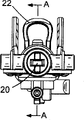
With reference to figure 1, scroll saw 2 has shell 4, and shell 4 comprises one side of something 6 (only illustrating among Fig. 1) of two shell types that form handle 8, and handle 8 has the starting switch 10 that is used to handle motor 12, and motor 12 supplies to have power supply by cable 14.Be used to be positioned over the bottom that base plate 16 on the workpiece (not shown) is positioned at this shell 4, scroll saw saw blade 18 (Fig. 2) is connected in the lower end of output shaft 20 by saw blade clamp mechanism 22.The operation of saw blade clamp mechanism 22 does not relate to the understanding of the present invention, therefore here is not described in detail.The orientation of base plate 16 can be regulated so that can cut by hypotenuse with respect to shell 4, and can fix by enough pinching screws of being handled by retaining mechanism 26 24, and it does not relate to the understanding of the present invention yet, therefore here is not described in detail.
Motor 12 drives the axle 28 that fan 30 is housed.When fan 30 rotation, air is discharged and can be used to blow off near the saw blade 18 sawdust through conduit 32, and sucks air with cooling motor 12 by the inlet on the shell 4 34.Axle 28 is equipped with the pinion 36 with driving gear 38 engagements, and this driving gear 38 is equipped with a cam face 42 around axis 40 installations and in its front.Cam-follower 44 selectively meshes with cam face 42 by the cam portion 46 of scrolling selector 48, so that handle the track pattern of scroll saw in the mode of describing in detail below.Gear 38 also is equipped with a cam pin 50, and this cam pin slidably is installed in the groove 52 of Scotland yoke mechanism 54, and this Scotland yoke mechanism 54 is installed on the output shaft 20.
With reference to figure 2, scrolling knob 56 is installed on the shell 4 in rotatable mode, is used to regulate the orientation of saw blade 18 with respect to shell 4.This scrolling knob 56 has collar portion 58, has cruciform vent 60 in it, and the effect in this hole will be discussed in more detail below.Saw blade supporting component 62 has supporting bracket 64, and supporting bracket 64 has gudgeon 66, and it is received within the shell 4 corresponding grooves (not shown), so that assembly 62 can pivot with respect to shell 4 around the X-X axis in the track pattern of scroll saw.Upper bearing 68 (Fig. 3) has a part spherical portion 70, it can rotate around the Y-Y axis with respect to supporting bracket 64, and has the groove 72 that is used to admit output shaft 20, so that output shaft 20 can slide with respect to upper bearing (metal) 68 at the Y-Y axis direction, but prevent that it from moving with respect to upper bearing (metal) 68 in the direction transverse to the Y-Y axis.This upper bearing (metal) 68 also has a pair of supporting leg 74, it is received within the cross bore 60 of scrolling knob 56, so that bearing 68 (and therefore making output shaft 20) is rotated around the Y-Y axis with scrolling knob 56, and bearing 68 allows with respect to the limited pivoting action of scrolling knob 56 around the X-X axis.
The mechanism of selecting between scrolling, track and the normal mode of scroll saw is shown specifically with reference to Figure 4 and 5.Locking arm 76 slidably is installed in the shell 4, and between two upper positions shown in the lower position shown in Fig. 5 (a) and Fig. 5 (b) and 5 (c), can move, wherein, in lower position, scrolling knob 56 can rotate with respect to shell 4, the upper end 78 of locking arm 76 is received within one or more grooves 80 of scrolling knob 56 downsides in two upper positions, rotates around the Y-Y axis with respect to shell 4 to prevent scrolling knob 56.Scrolling selector 48 is installed in the shell 4 with rotary way, and can rotate by the model selection knob (not shown) on the shell 4, and, the lower end 82 of locking arm 76 has sphering groove 84, its admittance is arranged on the sphering tooth 86 on the scrolling selector 48, so that scrolling selector 48 causes that with respect to the rotation of shell 4 locking arm 76 is parallel to the motion of Y-Y axis.Scrolling selector 48 also has a cam face, and this cam face is a projection 46 in the embodiment shown in fig. 1, and is groove 88 at Fig. 5 (a) to the embodiment shown in Fig. 5 (c).
With reference to figure 5 (a) to Fig. 5 (c), in the position shown in Fig. 5 (a), scrolling selector 48 makes the upper end 78 of locking arm 76 not be received within any groove 80 of scrolling knob 56 with respect to shell 4 around the position of rotation of axis 90, consequently, scrolling knob 56 (and therefore also having output shaft 20 and scroll saw saw blade 18) can be around the Y-Y axis with respect to shell 4 rotations, so that saw blade 18 can carry out the scrolling motion.Simultaneously and since when saw blade 18 be not to be difficult to track pattern operation scroll saw forward the time with respect to the orientation of shell 4, so when scroll saw is in Scroll Mode, wish to prevent the orbital motion of saw blade 18.This realizes that in the position shown in Fig. 5 (a) because the bottom 82 of locking arm 76 is not received within the groove 88, consequently locking arm 76 is pushed away forward with respect to scrolling selector 48.And then this is again in abutting connection with the bottom 92 (Fig. 2) of bracing frame 64, and this causes that supporting component 62 pivots forward around the effect that the X-X axis overcomes the spring (not shown), so the cam surface 42 on cam-follower 44 maintenances and the gear 38 is disengaged.As a result, oscillating motion can not pass to supporting component 62 when gear 38 rotations.
When scrolling selector 48 during around the position of axis 90 counter rotations shown in Fig. 5 (b), tooth 86 causes that with the engagement of groove 84 locking arm 76 moves up, therefore in 78 grooves 80 that are received within the scrolling knob 56 of upper end, to prevent that scrolling knob 56 is with respect to shell 4 rotations.Simultaneously, the lower end 82 of locking arm 76 still is not received in the groove 88 because this result, cam-follower 44 still keeps and gear 38 on cam face 42 be disengaged, so oscillating motion can not be delivered to supporting component 62.
Select 48 when axis 90 counter-clockwise direction are further rotated position shown in Fig. 5 (c) when scrolling, the upper end 78 of locking arm 76 still is received within the groove 80, but the lower end 82 of locking arm 76 is received within the groove 88 on the scrolling selector 48 now.As a result, supporting component 62 and locking arm 76 make cam-follower 44 engage with cam face 42 on the gear 38 can pivoting under the effect of spring (not shown), and therefore, the swing interaction energy is delivered to supporting component 62 when gear 38 is rotated by motor 12.Therefore, can see that do not allow Scroll Mode when track pattern works, vice versa.By handling locking arm 76 by means of the engagement of tooth 86 in groove 84 (different) with the rack-and-pinion of cooperation, provide remarkable simplification scrolling retaining mechanism to make and the advantage of assembling, this so reduced the manufacturing cost of scroll saw again.
To Fig. 6 (c), output shaft 20 has rectangular cross section on most of length with reference to figure 6 (a).The advantage of She Zhiing is that axle 20 end can be installed on the contiguous parts and the cross-shaped pin (this pin is necessary under the situation of circular cross section axle) that does not need to pass axle in irrotational mode like this, this pin need be installed in the groove the inside, and the distance that cross pin moved when this groove moved back and forth with axle 20 at least is the same dark.As a result, scroll saw can manufacture more compact structure than the situation of circular cross section axle at the parts of axle 20 ends.
For axle 20 can be rotated with respect to Scotland yoke 54 in the Scroll Mode of scroll saw, the insert 94 of a pair of roughly D shape is installed in the relative both sides of axle 20, for this part of axle provides the part circular external cross section, and Scotland yoke 54 is installed on the axle 20 in rotatable mode by the circular hole in the lower flange on it 98 96.Then, yoke 54 usefulness pins 100 in Scotland pass D shape insert 94 and axle 20 is fixed on the axle 20, so that Scotland yoke 54 can not be moved axially with respect to axle 20, but can pivot with respect to axle, so regardless of the orientation of saw blade 18 with respect to shell 4, the groove 52 of Scotland yoke 54 keeps in the face of cam pin 50 (Fig. 1).This make when scroll saw during at Scroll Mode saw blade 18 can back and forth be driven.
The supporting component 62 of Fig. 2 at length illustrates in Fig. 7 to Figure 13.Lower bearing 102 is to be installed on the supporting bracket 64 around the rotatable mode of the longitudinal axis of output shaft 20, and has a groove of the groove 72 that is similar in the upper bearing (metal) 68, be used for admitting slidably axle 20, so that axle can carry out reciprocal axial motion with respect to bearing 68,102, but prevent that axle is in the direction motion transverse to its longitudinal axis.Lower bearing 102 has four supporting legs that stretch out 104 in its lower end, so that cross bath (Figure 11) is formed between this supporting leg 104, be used to admit axle 20 and cooperate with the rib 120 on being arranged on control bearing 106, thus output shaft during around its longitudinal axis rotation control bearing 106 rotate with lower bearing 102 and output shaft 20.Control bearing 106 is installed in supporting bracket 64 by flange on the supporting bracket 64 116 and the groove engagement of controlling in the bearing 106 in rotatable mode.
Control bearing 106 has support arm 108, and support arm 108 is equipped with saw blade backing roll 110 at its far-end.Saw blade backing roll 110 has groove 112 (Fig. 2), the back side that is used to admit scroll saw saw blade 18.Because control bearing 106 is installed on the supporting bracket 64 in rotatable mode, saw blade backing roll 110 all keeps in scrolling, track and the normal mode of scroll saw and the contacting of scroll saw saw blade 18.The size of lower bearing 102, control bearing 106 and supporting bracket 64 is made and is made control bearing 106 carry out limited pivot with respect to the axis that lower bearing 102 winds transverse to axle 20 longitudinal axis, and can carry out finite motion with respect to supporting bracket 64, because the motion that the gap 122 between control bearing 106 and the supporting bracket 64 causes is eliminated by elastic sealing element 118, elastic packing 118 also prevents the internal leak of lubricant from supporting component 62.
With reference to Figure 12 and 13, when scroll saw was used to the cut workpiece (not shown), the reaction force that workpiece acts on the saw blade 18 tended to cause that saw blade 18 is pivoted to position shown in Figure 13 with respect to output shaft 20 from position counter-clockwise direction shown in Figure 12.As a result, rotating torque is applied on the support arm 108 by saw blade backing roll 110 direction shown in the arrow C in Figure 13.Because gap 122 is reduced to state shown in Figure 13 from state shown in Figure 12, the opposite rotating torque that the supported support 64 of this rotating torque is applied on the control bearing 106 is offset.
But because the limited pivoting action that allows between control bearing 106 and the lower bearing 102, the rotating torque that 108 pairs of supporting brackets 64 of support arm are applied is not delivered to lower bearing 102, and therefore is not delivered to output shaft 20.Therefore have following advantage, if promptly frictional force F (Figure 13) acts on the saw blade backing roll 110, the frictional force between lower bearing 102 and the axle 20 does not increase as a result.
It will be appreciated by persons skilled in the art that the above-mentioned only embodiment by case description is not a limitation of the present invention, and under the situation that does not depart from the scope of the invention that limits by accessory claim, can carry out various changes and modification.
Claims (11)
1. output shaft assembly that is used for electric tool, this instrument has a tool outer casing, a motor and an output shaft that is arranged in this tool outer casing, this output shaft is suitable for respect to this tool outer casing in the reciprocating motion mode by this motor-driven, and support the operation element of this instrument, this operation element is moved back and forth with respect to this tool outer casing, and this output shaft assembly comprises:
An output shaft, it has first and second parts of the respective end of being close to described axle and has non-circular cross sections in the longitudinal axis transverse to described axle, and at least one third part between described first and second parts, its in use the direction transverse to the longitudinal axis of described axle have to small part be almost circular external cross section, so that described axle pivots around described longitudinal axis with respect to driving mechanism, this driving mechanism is used for driving described axle with respect to this tool outer casing in the reciprocating motion mode.
2. according to the assembly of claim 1, wherein, at least one described third part is to be made of a plurality of inserts that in use are installed on this output shaft.
3. according to the assembly of claim 2, wherein, before described insert was installed on described output shaft, this output shaft had the cross section of basically identical in the direction transverse to described longitudinal axis.
4. according to the assembly of claim 2 or 3, wherein, at least one described insert has the cross section of D shape shape substantially.
5. any one assembly of 1-3 in requiring according to aforesaid right, comprise that also at least one is in use can the pivot mode to be installed on the driver part at least one described third part, it is used for and drive mechanism engages, and this driving mechanism is used for driving described axle with respect to this tool outer casing in the reciprocating cutter mode.
6. electric tool, it comprises a tool outer casing, a motor and an output shaft assembly that is arranged in this tool outer casing, this output shaft assembly has an output shaft, it is suitable for respect to this tool outer casing in the reciprocating motion mode by this motor-driven, and support the operation element of this instrument, this operation element is moved back and forth with respect to this tool outer casing, and this output shaft assembly comprises:
An output shaft, it has first and second parts of the respective end of being close to described axle and has non-circular cross sections in the longitudinal axis transverse to described axle, and at least one third part between described first and second parts, its in use the direction transverse to the longitudinal axis of described axle have to small part be almost circular external cross section, so that described axle pivots around described longitudinal axis with respect to driving mechanism, this driving mechanism is used for driving described axle with respect to this tool outer casing in the reciprocating motion mode.
7. according to the assembly of claim 6, wherein, at least one described third part is to be made of a plurality of inserts that in use are installed on this output shaft.
8. according to the assembly of claim 7, wherein, before described insert was installed on described output shaft, this output shaft had the cross section of basically identical in the direction transverse to described longitudinal axis.
9. according to the assembly of claim 7, wherein, at least one described insert has the cross section of D shape shape substantially.
10. according to the assembly of claim 6, wherein, also comprise at least one in use can the pivot mode to be installed on the driver part at least one described third part, it is used for and drive mechanism engages, and this driving mechanism is used for driving described axle with respect to this tool outer casing in the reciprocating cutter mode.
11. the electric tool of any one in requiring according to aforesaid right, wherein this electric tool is a scroll saw.
Applications Claiming Priority (2)
| Application Number | Priority Date | Filing Date | Title |
|---|---|---|---|
| EP04252941.2 | 2004-05-18 | ||
| EP04252941A EP1598136B1 (en) | 2004-05-18 | 2004-05-18 | Output shaft assembly for power tool and power tool incorporating such assembly |
Publications (1)
| Publication Number | Publication Date |
|---|---|
| CN1699002A true CN1699002A (en) | 2005-11-23 |
Family
ID=34930322
Family Applications (1)
| Application Number | Title | Priority Date | Filing Date |
|---|---|---|---|
| CN200510070857.1A Pending CN1699002A (en) | 2004-05-18 | 2005-05-18 | Output shaft assembly for power tool and power tool incorporating such assembly |
Country Status (6)
| Country | Link |
|---|---|
| US (1) | US20050257383A1 (en) |
| EP (1) | EP1598136B1 (en) |
| CN (1) | CN1699002A (en) |
| AT (1) | ATE340670T1 (en) |
| AU (1) | AU2004203090A1 (en) |
| DE (1) | DE602004002572T2 (en) |
Cited By (3)
| Publication number | Priority date | Publication date | Assignee | Title |
|---|---|---|---|---|
| CN102271849A (en) * | 2009-01-05 | 2011-12-07 | 罗伯特·博世有限公司 | Motor-driven machine tool |
| CN101284320B (en) * | 2007-04-13 | 2011-12-07 | 苏州宝时得电动工具有限公司 | Reciprocating cutting tool |
| CN111644695A (en) * | 2019-03-04 | 2020-09-11 | 株式会社牧田 | Reciprocating tool |
Families Citing this family (15)
| Publication number | Priority date | Publication date | Assignee | Title |
|---|---|---|---|---|
| DE602004012977T2 (en) * | 2004-05-18 | 2009-05-20 | Black & Decker Inc., Newark | Power tool with a mode selection mechanism |
| US10029322B2 (en) | 2007-09-21 | 2018-07-24 | Black & Decker Inc. | Housing of a cutting tool including blade storage, integral blade guard and motor ventilation pathway |
| US9827623B2 (en) | 2007-09-21 | 2017-11-28 | Black & Decker Inc. | Control of reciprocation speed and orbital magnitude of a jigsaw with a plurality of material and/or task descriptive icons |
| US8033026B2 (en) | 2007-09-21 | 2011-10-11 | Black & Decker Inc. | Adjustable and removable keel assembly and blade guide for a jigsaw |
| US9981327B2 (en) | 2007-09-21 | 2018-05-29 | Black & Decker Inc. | Cutting angle indicator in jigsaw housing with dust extraction |
| DE102008001769A1 (en) | 2008-05-14 | 2009-11-19 | Robert Bosch Gmbh | Machine tool, in particular hand-held machine tool |
| DE102008001772A1 (en) * | 2008-05-14 | 2009-11-19 | Robert Bosch Gmbh | Machine tool, in particular hand-held machine tool |
| DE102008001753A1 (en) * | 2008-05-14 | 2009-11-19 | Robert Bosch Gmbh | Machine tool, in particular hand-held machine tool |
| DE102008001775A1 (en) | 2008-05-14 | 2009-11-19 | Robert Bosch Gmbh | Machine tool, in particular hand-held machine tool |
| DE102009000032A1 (en) * | 2009-01-05 | 2010-07-08 | Robert Bosch Gmbh | Motor driven machine tool |
| DE102009046374A1 (en) * | 2009-10-23 | 2011-04-28 | Robert Bosch Gmbh | machine tool |
| EP2694260B1 (en) | 2011-04-01 | 2017-01-18 | Milwaukee Electric Tool Corporation | Jigsaw |
| US8578615B2 (en) | 2011-09-12 | 2013-11-12 | Black & Decker Inc. | Jigsaw with deployable keel and tiltable shoe |
| US9559628B2 (en) | 2013-10-25 | 2017-01-31 | Black & Decker Inc. | Handheld power tool with compact AC switch |
| EP4072769A4 (en) * | 2019-12-10 | 2023-12-27 | Milwaukee Electric Tool Corporation | Reciprocating saw |
Family Cites Families (51)
| Publication number | Priority date | Publication date | Assignee | Title |
|---|---|---|---|---|
| US161585A (en) * | 1875-03-30 | Improvement in scroll-sawing-machines | ||
| US229908A (en) * | 1880-07-13 | Edwaed nunatf | ||
| US2506736A (en) * | 1947-04-01 | 1950-05-09 | Scintilla Ag | Motor-driven hand tool |
| US2781800A (en) * | 1954-11-05 | 1957-02-19 | Walter A Papworth | Manually portable bayonet saw with oval stroke |
| US2980979A (en) * | 1959-02-09 | 1961-04-25 | Novelo John | Concrete tie rod |
| US3095748A (en) * | 1961-06-16 | 1963-07-02 | Porter Cable Machine Co | Orbital motion tool |
| US3388728A (en) * | 1966-04-15 | 1968-06-18 | Martin Marietta Corp | Portable power tools |
| US3484917A (en) * | 1967-05-09 | 1969-12-23 | Mc Graw Edison Co | Combination power tool |
| US3494391A (en) * | 1968-04-24 | 1970-02-10 | Singer Co | Sabre saws with 360 degree swivel saw bars |
| US3665983A (en) * | 1970-12-15 | 1972-05-30 | Singer Co | Sabre saws with angularly adjustable swivel saw bars |
| US3729822A (en) * | 1972-03-09 | 1973-05-01 | Singer Co | Sabre saws with lockable swivel saw bars |
| DE7513910U (en) * | 1975-04-30 | 1976-11-04 | Scintilla Ag, Solothurn (Schweiz) | ADDITIONAL HANDLE, IN PARTICULAR FOR POWER TOOLS |
| US3965344A (en) * | 1975-07-24 | 1976-06-22 | International Telephone And Telegraph Corporation | Computer utilizing logarithmic function generators |
| DE2655583C2 (en) * | 1976-12-08 | 1982-07-01 | Black & Decker, Inc., 19711 Newark, Del. | Jigsaw |
| US4262421A (en) * | 1978-08-11 | 1981-04-21 | Eugen Lutz Gmbh & Co. Maschinenfabrik | Keyhole saw |
| US4238884A (en) * | 1979-06-19 | 1980-12-16 | Black & Decker Inc. | Orbital jig saw |
| US4272996A (en) * | 1979-06-19 | 1981-06-16 | Black & Decker Inc. | Scotch yoke having a curved track |
| US4262420A (en) * | 1979-12-14 | 1981-04-21 | The Singer Company | Crosshead for sabre saws and sabre saws incorporating same |
| US4283855A (en) * | 1980-04-07 | 1981-08-18 | The Singer Company | Sabre saw with rotatable saw bar |
| US4351112A (en) * | 1981-02-20 | 1982-09-28 | The Singer Company | Sabre saw bar and blade holder |
| US4512078A (en) * | 1982-04-20 | 1985-04-23 | Black & Decker Inc. | Jig saw with orbital mechanism |
| US4470327A (en) * | 1982-09-01 | 1984-09-11 | Gerber Legendary Blades | Adjustable balance handle for knife |
| US4550501A (en) * | 1984-01-23 | 1985-11-05 | Black & Decker Inc. | Orbital-action reciprocating power saw |
| US4545123A (en) * | 1984-04-09 | 1985-10-08 | Skil Corporation | Combination jig saw adjusting mechanism |
| GB2158393B (en) * | 1984-05-11 | 1987-05-20 | Black & Decker Inc | Scroller jig saw |
| US4592144A (en) * | 1984-06-22 | 1986-06-03 | The Singer Company | Molded scroller saw lock button spring |
| US4628605A (en) * | 1985-06-10 | 1986-12-16 | Porter-Cable Corporation | Orbital bayonet saw |
| DE3635470A1 (en) * | 1986-10-18 | 1988-04-21 | Licentia Gmbh | Jigsaw |
| DE4001996A1 (en) * | 1990-01-24 | 1991-07-25 | Scintilla Ag | Reciprocating swing saw with blade carrying bar - which is guided without clearance in transverse direction in swing plane |
| GB9101460D0 (en) * | 1991-01-23 | 1991-03-06 | Black & Decker Inc | Pendulum jigsaws |
| DE4138986A1 (en) * | 1991-11-27 | 1993-06-03 | Atlas Copco Elektrowerkzeuge | TENSIONING DEVICE FOR A JIG SAWING MACHINE |
| US5355708A (en) * | 1993-12-20 | 1994-10-18 | Kauffman Kenneth A | Straight rod stock processor |
| JP3212792B2 (en) * | 1994-02-10 | 2001-09-25 | 株式会社マキタ | Jigsaw |
| US5522281A (en) * | 1994-10-31 | 1996-06-04 | Chrysler Corporation | Adjustable tie-rod assembly for a motor vehicle |
| EP0716897B1 (en) * | 1994-12-16 | 1999-08-11 | CEKA ELEKTROWERKZEUGE AG + Co.KG | Reciprocating and oscillating drive for sabre saws |
| DE69621268T2 (en) * | 1995-02-15 | 2003-01-09 | Makita Corp | Saw blade clamping device for cutting tools |
| US5727322A (en) * | 1996-12-31 | 1998-03-17 | Black & Decker Inc. | Adjustable shoe for a jig saw |
| US6802646B1 (en) * | 2001-04-30 | 2004-10-12 | General Nanotechnology Llc | Low-friction moving interfaces in micromachines and nanomachines |
| JP3710697B2 (en) * | 2000-09-19 | 2005-10-26 | 株式会社マキタ | Reciprocating cutting tool |
| NL1016427C2 (en) * | 2000-10-18 | 2002-04-22 | Skil Europ Bv | Holder for a saw blade of a jigsaw. |
| US6735876B2 (en) * | 2001-03-01 | 2004-05-18 | Makita Corporation | Blade clamps suitable for reciprocating power tools |
| US6912790B2 (en) * | 2001-12-03 | 2005-07-05 | Milwaukee Electric Tool Corporation | Handle arrangement for a reciprocating saw |
| US6671969B2 (en) * | 2001-12-18 | 2004-01-06 | Porter-Cable/Delta | Adjustable shoe for a reciprocating saw |
| JP4244615B2 (en) * | 2002-04-22 | 2009-03-25 | 日立工機株式会社 | Electric cutting machine |
| GB2393934A (en) * | 2002-10-07 | 2004-04-14 | Black & Decker Inc | A reciprocating saw with two eccentrics |
| GB2394692B (en) * | 2002-10-28 | 2005-08-17 | Black & Decker Inc | Support mechanism for reciprocating tool and tool incorporating such mechanism |
| US7234243B2 (en) * | 2003-06-25 | 2007-06-26 | Credo Technology Corporation | Reciprocating cutting tool with orbital action |
| GB0405729D0 (en) * | 2004-03-15 | 2004-04-21 | Gmca Pty Ltd | Power tool bearing arrangement |
| EP1598135B1 (en) * | 2004-05-18 | 2008-09-10 | BLACK & DECKER INC. | Support assembly for output shaft of reciprocating power tool |
| DE602004012977T2 (en) * | 2004-05-18 | 2009-05-20 | Black & Decker Inc., Newark | Power tool with a mode selection mechanism |
| CN2747008Y (en) * | 2004-06-01 | 2005-12-21 | 南京德朔实业有限公司 | Turning saw |
-
2004
- 2004-05-18 DE DE602004002572T patent/DE602004002572T2/en active Active
- 2004-05-18 AT AT04252941T patent/ATE340670T1/en not_active IP Right Cessation
- 2004-05-18 EP EP04252941A patent/EP1598136B1/en active Active
- 2004-07-08 AU AU2004203090A patent/AU2004203090A1/en not_active Abandoned
- 2004-07-29 US US10/902,745 patent/US20050257383A1/en not_active Abandoned
-
2005
- 2005-05-18 CN CN200510070857.1A patent/CN1699002A/en active Pending
Cited By (5)
| Publication number | Priority date | Publication date | Assignee | Title |
|---|---|---|---|---|
| CN101284320B (en) * | 2007-04-13 | 2011-12-07 | 苏州宝时得电动工具有限公司 | Reciprocating cutting tool |
| CN102271849A (en) * | 2009-01-05 | 2011-12-07 | 罗伯特·博世有限公司 | Motor-driven machine tool |
| CN102271849B (en) * | 2009-01-05 | 2014-12-31 | 罗伯特·博世有限公司 | Motor-driven machine tool |
| CN111644695A (en) * | 2019-03-04 | 2020-09-11 | 株式会社牧田 | Reciprocating tool |
| CN111644695B (en) * | 2019-03-04 | 2023-09-19 | 株式会社牧田 | reciprocating tool |
Also Published As
| Publication number | Publication date |
|---|---|
| EP1598136B1 (en) | 2006-09-27 |
| ATE340670T1 (en) | 2006-10-15 |
| EP1598136A1 (en) | 2005-11-23 |
| AU2004203090A1 (en) | 2005-12-08 |
| DE602004002572T2 (en) | 2007-07-12 |
| DE602004002572D1 (en) | 2006-11-09 |
| US20050257383A1 (en) | 2005-11-24 |
Similar Documents
| Publication | Publication Date | Title |
|---|---|---|
| CN1699002A (en) | Output shaft assembly for power tool and power tool incorporating such assembly | |
| CN1699027A (en) | Mode selection mechanism for power tool, and power tool incorporating such mechanism | |
| CN1699003A (en) | Support assembly for output shaft of reciprocating power tool | |
| US7637018B2 (en) | Power tool | |
| CN1290656C (en) | Reciprocating-type saw | |
| US6357125B1 (en) | Adjustable stroke mechanism for a scotch yoke assembly | |
| US7707729B2 (en) | Drive mechanism for a reciprocating tool | |
| CN1572447A (en) | Support mechanism for reciprocating tool and tool incorporating such mechanism | |
| CN1807026A (en) | Power tool | |
| GB2415661A (en) | An anti-rotation mechanism for a reciprocating saw | |
| EP1232817A2 (en) | Reciprocating power tools | |
| CN1266763A (en) | Cutting mechanism of knife saw | |
| CN1048082C (en) | Rotary motion mechanism | |
| JP2005528227A (en) | Robot arm drive unit | |
| CN200978930Y (en) | Working arm drive structure | |
| CN2866006Y (en) | Ratchet spanner | |
| CN111775139B (en) | Robot | |
| JP2004224464A (en) | Workpiece inversion system | |
| CN217583059U (en) | Swinging shifting fork arm driving assembly on diamond grinding and polishing machine | |
| CN214533663U (en) | Oscillating device of tower fan | |
| KR100958731B1 (en) | Linearly reciprocating transfer device | |
| CN115013638A (en) | Pipeline transportation robot | |
| CN1593856A (en) | Reciprocating saw and guard rail assembly therefor | |
| CN2541106Y (en) | Reciprocating mechanism of electric bow | |
| CN2848429Y (en) | Saw blade aligning mechanism of table saw |
Legal Events
| Date | Code | Title | Description |
|---|---|---|---|
| C06 | Publication | ||
| PB01 | Publication | ||
| C10 | Entry into substantive examination | ||
| SE01 | Entry into force of request for substantive examination | ||
| C02 | Deemed withdrawal of patent application after publication (patent law 2001) | ||
| WD01 | Invention patent application deemed withdrawn after publication |