CN1663132A - Low frequency attenuating circuit - Google Patents
Low frequency attenuating circuit Download PDFInfo
- Publication number
- CN1663132A CN1663132A CN03814209.0A CN03814209A CN1663132A CN 1663132 A CN1663132 A CN 1663132A CN 03814209 A CN03814209 A CN 03814209A CN 1663132 A CN1663132 A CN 1663132A
- Authority
- CN
- China
- Prior art keywords
- switch
- resistance
- rectified signal
- frequency
- circuit
- Prior art date
- Legal status (The legal status is an assumption and is not a legal conclusion. Google has not performed a legal analysis and makes no representation as to the accuracy of the status listed.)
- Pending
Links
Images


Classifications
-
- H—ELECTRICITY
- H04—ELECTRIC COMMUNICATION TECHNIQUE
- H04B—TRANSMISSION
- H04B1/00—Details of transmission systems, not covered by a single one of groups H04B3/00 - H04B13/00; Details of transmission systems not characterised by the medium used for transmission
- H04B1/005—Details of transmission systems, not covered by a single one of groups H04B3/00 - H04B13/00; Details of transmission systems not characterised by the medium used for transmission adapting radio receivers, transmitters andtransceivers for operation on two or more bands, i.e. frequency ranges
-
- H—ELECTRICITY
- H04—ELECTRIC COMMUNICATION TECHNIQUE
- H04B—TRANSMISSION
- H04B1/00—Details of transmission systems, not covered by a single one of groups H04B3/00 - H04B13/00; Details of transmission systems not characterised by the medium used for transmission
- H04B1/06—Receivers
- H04B1/16—Circuits
-
- H—ELECTRICITY
- H04—ELECTRIC COMMUNICATION TECHNIQUE
- H04B—TRANSMISSION
- H04B1/00—Details of transmission systems, not covered by a single one of groups H04B3/00 - H04B13/00; Details of transmission systems not characterised by the medium used for transmission
- H04B1/38—Transceivers, i.e. devices in which transmitter and receiver form a structural unit and in which at least one part is used for functions of transmitting and receiving
- H04B1/40—Circuits
- H04B1/403—Circuits using the same oscillator for generating both the transmitter frequency and the receiver local oscillator frequency
- H04B1/406—Circuits using the same oscillator for generating both the transmitter frequency and the receiver local oscillator frequency with more than one transmission mode, e.g. analog and digital modes
Landscapes
- Engineering & Computer Science (AREA)
- Computer Networks & Wireless Communication (AREA)
- Signal Processing (AREA)
- Circuits Of Receivers In General (AREA)
- Filters And Equalizers (AREA)
- Attenuators (AREA)
- Superheterodyne Receivers (AREA)
- Noise Elimination (AREA)
Abstract
Description
技术领域technical field
本发明涉及使AM/FM检波信号的低频分量衰减的低频衰减电路以及无线电接收机。The present invention relates to a low frequency attenuation circuit for attenuating low frequency components of an AM/FM detection signal and a radio receiver.
背景技术Background technique
接收AM广播的无线电接收机,通常,为了提高听觉特性,具有在AM检波信号中使100Hz左右以下的频率分量衰减的低频衰减电路(AM低截止(low cut)电路)。A radio receiver that receives AM broadcasts generally has a low-frequency attenuation circuit (AM low cut circuit) that attenuates frequency components below about 100 Hz in an AM detection signal in order to improve auditory characteristics.
图1是具备已有的低频衰减电路的无线电接收机的一例的结构图。这里,表示可按收FM广播和AM广播两者的FM/AM无线电接收机。FIG. 1 is a configuration diagram of an example of a radio receiver including a conventional low-frequency attenuation circuit. Here, an FM/AM radio receiver capable of receiving both FM broadcast and AM broadcast is shown.
FM信号经FM前端(front end)电路1被接收,再由IF放大器2放大后,经FM检波电路3进行FM检波。该FM检波信号经电容4将其直流分量滤除后,输出到扬声器6。此外,FM检波信号在立体声解调部5进行立体声解调。The FM signal is received by the FM front end circuit 1, and then amplified by the IF amplifier 2, and then FM detection is performed by the
另一方面,AM信号经AM前端电路11被接收,再由IF放大器12放大后,经AM检波电路13进行AM检波。该检波信号经低频衰减电路14将其低频分量(例如100Hz以下的分量)滤除后,输出到扬声器6。On the other hand, the AM signal is received by the AM front-end circuit 11 , amplified by the IF amplifier 12 , and AM detected by the
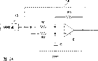
图2A是低频衰减电路14的一例的电路图。低频衰减电路14具备运算放大器21、电阻R1~R3以及电容C。AM检波电路13的输出经电阻R1供给到放大器21的反相输入端,同时经电阻R2供给到运算放大器21的非反相输入端。此处,运算放大器21的非反相输入端经电容C接地。运算放大器21的输出经电阻R3反馈到放大器21的反相输入端。FIG. 2A is a circuit diagram of an example of the low
上述结构的低频衰减电路14,相对于高频分量,按图2B所示的状态动作。即,相对于高频分量,电容C的阻抗降低,所以运算放大器21的非反相输入端成为接地状态。因此,这种情况下,输出信号Vout成为具有与输入信号Vin成比例的振幅的信号。The low-
另一方面,低频衰减电路14,相对于低频分量,按图2C所示的状态动作。即,相对于低频分量,电容C的阻抗增大,因此,如果设电阻R1=电阻R2,则运算放大器21的非反相输入端会输入与该反相输入端相同相位的信号。因此,这种情况下,输出信号Vout的振幅减小。On the other hand, the low-
象这样,低频衰减电路14使高频分量通过的同时,也使低频分量衰减。In this way, the low-
但是,一般地,要求无线电接收机小型化和低成本化。具体地说,希望接收电路的IC化(最终为1芯片化)。However, in general, miniaturization and cost reduction of radio receivers are required. Specifically, it is desired to convert the receiving circuit into an IC (eventually, 1 chip).
如果使用图2A所示的低频衰减电路14来使100Hz左右以下的频率分量发生衰减,则必须增大电容C。即,在这种情况下,电容C不能形成在IC上,而是成为了所谓的“外挂部件”。其结果,低频衰减电路14的安装面积增大,还成了低成本化的障碍。If the low-
发明内容Contents of the invention
本发明的目的在于谋求使AM/FM检波信号的低频分量衰减的低频衰减电路的小型化。An object of the present invention is to reduce the size of a low-frequency attenuation circuit for attenuating low-frequency components of AM/FM detection signals.
本发明的低频衰减电路是以被使用在FM/AM无线电接收机中为前提的,其具有:选择FM检波信号或AM检波信号的第1开关;设置在上述第1开关输出一侧的电容;多个设置在上述第1开关输出一侧的电阻,以及使用通过上述第1开关选择了AM检波信号时从上述多个电阻中选择的电阻和上述电容,从而构成上述AM检波信号用的高通滤波器的第2开关。此时,上述第1开关、上述多个电阻、以及上述第2开关可以形成在1个IC上。The low-frequency attenuation circuit of the present invention is based on the premise of being used in an FM/AM radio receiver, and has: a first switch for selecting an FM detection signal or an AM detection signal; a capacitor provided on the output side of the first switch; A plurality of resistors provided on the output side of the first switch, and a resistor selected from the plurality of resistors when the AM detection signal is selected by the first switch and the capacitor are used to form a high-pass filter for the AM detection signal. 2nd switch of the device. In this case, the first switch, the plurality of resistors, and the second switch may be formed on one IC.
上述低频衰减电路中,电容用于滤除FM检波信号的直流分量以及使AM检波信号的低频分量衰减这两方面。因此,不必设计仅仅使AM检波信号的低频分量衰减的电容。其结果,能谋求电路规模的小型化、电路的IC化以及无线电接收机的低成本化。In the above low-frequency attenuation circuit, the capacitor is used to filter out the DC component of the FM detection signal and attenuate the low-frequency component of the AM detection signal. Therefore, it is not necessary to design a capacitor for attenuating only the low-frequency components of the AM detection signal. As a result, miniaturization of the circuit scale, IC of the circuit, and cost reduction of the radio receiver can be achieved.
另外,AM检波信号用的高通滤波器的截止频率,通过从多个电阻中选择适当的电阻来进行调整。因此,能够容易地使所希望的频率衰减。In addition, the cutoff frequency of the high-pass filter for the AM detection signal is adjusted by selecting an appropriate resistor from a plurality of resistors. Therefore, it is possible to easily attenuate a desired frequency.
此外,在上述FM/AM无线电接收机具备使检波信号的高频分量衰减的高频衰减电路时,第2开关也可以基于该高频衰减电路的动作,从上述多个电阻中选择所对应的电阻。通过使低频衰减动作和高频衰减动作联合动作,能容易地得到最佳的听觉效果。In addition, when the above-mentioned FM/AM radio receiver includes a high-frequency attenuation circuit for attenuating high-frequency components of the detection signal, the second switch may select a corresponding one of the plurality of resistors based on the operation of the high-frequency attenuation circuit. resistance. The best auditory effect can be easily obtained by combining the low-frequency attenuation operation and the high-frequency attenuation operation.
另外,本发明不仅可以使AM检波信号的低频分量衰减,也可以使FM检波信号的低频分量衰减。In addition, the present invention can not only attenuate the low frequency components of the AM detection signal, but also attenuate the low frequency components of the FM detection signal.
附图说明Description of drawings
图1是具备已有的低频衰减电路的无线电接收机的一例的结构图。FIG. 1 is a configuration diagram of an example of a radio receiver including a conventional low-frequency attenuation circuit.
图2A~图2C是说明已有的低频衰减电路的结构及动作的图。2A to 2C are diagrams illustrating the configuration and operation of a conventional low frequency attenuation circuit.
图3是实施方式的低频衰减电路的结构图。FIG. 3 is a configuration diagram of a low frequency attenuation circuit according to the embodiment.
图4是表示实施方式的高通滤波器的特性的图。FIG. 4 is a graph showing characteristics of a high-pass filter according to the embodiment.
图5是表示具备低频衰减功能和高频衰减功能的接收机的结构图。FIG. 5 is a configuration diagram showing a receiver having a low-frequency attenuation function and a high-frequency attenuation function.
图6是对低频衰减功能和高频衰减功能的控制进行说明的图。FIG. 6 is a diagram illustrating control of a low-frequency attenuation function and a high-frequency attenuation function.
图7是电阻电路的其他实施例的图。FIG. 7 is a diagram of other embodiments of a resistor circuit.
图8是其他实施方式的低频衰减电路的结构图。FIG. 8 is a configuration diagram of a low-frequency attenuation circuit in another embodiment.
具体实施方式Detailed ways
下面参照附图说明本发明的实施方式。Embodiments of the present invention will be described below with reference to the drawings.
图3是实施方式的低频衰减电路的结构图。该低频衰减电路用于在AM/FM无线电接收机中使AM检波信号的低频分量发生衰减。FIG. 3 is a configuration diagram of a low frequency attenuation circuit according to the embodiment. The low frequency attenuation circuit is used to attenuate the low frequency components of an AM detection signal in an AM/FM radio receiver.
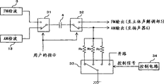
图3中,FM/AM切换开关(第1开关)31,按照用户的指示,选择从FM检波电路3输出的FM检波信号或者从AM检波电路13输出的AM检波信号中的一者。这里,FM检波电路3和AM检波电路13分别相当于图1所示的FM检波电路3和AM检波电路13,并通过已有的技术来实现。In FIG. 3 , an FM/AM selector switch (first switch) 31 selects either the FM detection signal output from the
电容4设置在FM/AM切换开关31的输出一侧,滤掉通过FM/AM切换开关31选择的信号的直流分量。该电容4相当于图1中用于滤掉FM检波信号的直流分量而设置的电容4。The
FM/AM切换开关32,按照用户的指示,向扬声器输出通过了电容4的信号。此外,FM/AM切换开关32,在通过FM/AM切换开关31选择了FM检波信号时,将通过了电容4的信号导向立体声解调部5,在通过FM/AM切换开关31选择了AM检波信号时,将通过了电容4的信号导向扬声器6。The FM/
电阻Ra,电阻Rb,电阻Rc是阻值互不相同的电阻,分别电连接在用于将通过了电容4的AM检波信号导向输出的路径上。另外,低截止(low cut)频率切换开关(第2开关)33,按照控制电路34生成的控制信号,从电阻Ra~Rc中选择对应的电阻并交流接地。另外,低截止频率切换开关33,在不选择任意一个电阻时,即没有由电容4和电阻构成的高通滤波器时,选择“开路”。此外,控制电路34例如能通过微型计算机实现。进而,如图3所示,用于从3个电阻中选择所希望的电阻的控制信号,例如通过2比特数据来实现。此外,虽然在图3中设有3个电阻(电阻Ra~Rc),但并不限于此,也可以设置2个或4个以上的电阻。The resistor Ra, the resistor Rb, and the resistor Rc are resistors with different resistance values, and are respectively electrically connected to the path for guiding the AM detection signal passing through the
在具备上述低频衰减电路的无线电接收机中,当用户选择了“FM”时,FM/AM切换开关31选择从FM检波电路3输出的FM检波信号,FM/AM切换开关32将通过了电容4的信号导向立体声解调部5。也就是,在这种情况下,电容4作为滤除FM检波信号的直流分量的隔直电容而起作用。此时,低截止频率切换开关33的状态并没有被特别限定。In the radio receiver with the above-mentioned low-frequency attenuation circuit, when the user selects "FM", the FM/
在上述无线电接收机中,当用户选择了“AM”时,FM/AM切换开关31选择从AM检波电路13输出的AM检波信号,FM/AM切换开关32将通过了电容4的信号导向扬声器6。低截止频率切换开关33按照来自控制电路34的控制信号,从电阻Ra~Rc中选择对应的电阻。因此,这种情况下,由电容4和所选择的电阻构成高通滤波器。也即是,例如在选择了电阻Ra时,形成了由电容4和电阻Ra构成的高通滤波器,在选择了电阻Rc时,形成了由电容4和电阻Rc构成的高通滤波器。该高通滤波器使AM检波信号中的低频分量发生衰减。In the above-mentioned radio receiver, when the user selects "AM", the FM/
此外,在没有从电阻Ra~Rc中选择任一电阻时,AM检波信号与FM检波信号同样地,仅通过电容4滤掉直流分量。In addition, when none of the resistors Ra to Rc is selected, only the DC component is filtered out by the
图4是表示上述高通滤波器特性的图。图4所示的特性a,特性b,特性c,特性d分别表示选择了电阻Ra,电阻Rb,电阻Rc时的滤波器的特性。象这样,高通滤波器的特性(此处为截止频率或低截止频率)能通过适当地选择电阻来进行调整。FIG. 4 is a graph showing the characteristics of the above-mentioned high-pass filter. The characteristics a, characteristics b, characteristics c, and characteristics d shown in FIG. 4 represent the characteristics of the filter when the resistance Ra, the resistance Rb, and the resistance Rc are selected, respectively. As such, the characteristics of the high-pass filter (here cut-off frequency or low cut-off frequency) can be adjusted by appropriate selection of resistors.
高通滤波器的特性调整例如按如下进行:即,在AM接收机中,公知的做法是通过使比预定频率(例如100Hz左右)低的低频侧的分量衰减,来提高听觉效果。因此,在实施方式的低频衰减电路中,从电阻Ra~Rc中选择合适的电阻,以使高通滤波器的截止频率达到上述预定的频率。The characteristic adjustment of the high-pass filter is performed, for example, as follows. In an AM receiver, it is known to attenuate low-frequency components lower than a predetermined frequency (for example, about 100 Hz) to improve auditory effects. Therefore, in the low-frequency attenuation circuit of the embodiment, an appropriate resistance is selected from the resistances Ra to Rc so that the cutoff frequency of the high-pass filter becomes the above-mentioned predetermined frequency.
此时,如果固定上述截止频率,则不必准备多个电阻(电阻Ra~Rc),只要事先设置对应该截止频率的电阻,就应该获得最佳的听觉效果。但实际上,由于构成无线电接收机的各种元件特性的偏差,能达到最佳听觉效果的频率并不一定是定值。因此,希望在无线电接收机出厂前,对上述高通滤波器的截止频率进行个别调整。At this time, if the above cutoff frequency is fixed, it is not necessary to prepare multiple resistors (resistors Ra~Rc), as long as the resistors corresponding to the cutoff frequency are set in advance, the best hearing effect should be obtained. But in fact, due to the deviation of the characteristics of various components that make up the radio receiver, the frequency that can achieve the best hearing effect is not necessarily a fixed value. Therefore, it is desirable to individually adjust the cutoff frequency of the above-mentioned high-pass filter before the radio receiver is shipped from the factory.
例如,图4中,设能得到最佳听觉效果的截止频率为“x”,则为得到特性b,控制电路34向低截止频率切换开关33供给内容为选择电阻Rb的控制信号。此处,特性b表示在频率x处,接收信号仅衰减预定量(例如3dB)的特性。此外,设能得到最佳听觉效果的截止频率为“y”,则为得到特性c,控制电路34向低截止频率切换开关33供给内容为选择电阻Rc的控制信号。此处,特性c表示在频率y处,接收信号仅衰减预定量的特性。For example, in FIG. 4 , assuming that the cutoff frequency that can obtain the best auditory effect is "x", then in order to obtain characteristic b, the
一般地,无线电接收机如图5所示,不仅具备用于使检波信号的低频分量衰减的功能(低频衰减电路41),还具备使其高频分量衰减的功能(高频衰减电路42)。此处,低频衰减电路41是参照图3说明的高通滤波器。另一方面,高频衰减电路42例如是低通滤波器,是用于使高频分量发生衰减,从而提高听觉效果的电路。Generally, as shown in FIG. 5 , a radio receiver has not only a function for attenuating low frequency components of a detection signal (low frequency attenuation circuit 41 ), but also a function for attenuating high frequency components thereof (high frequency attenuation circuit 42 ). Here, the low-frequency attenuation circuit 41 is a high-pass filter described with reference to FIG. 3 . On the other hand, the high-frequency attenuation circuit 42 is, for example, a low-pass filter, and is a circuit for attenuating high-frequency components to improve the auditory effect.
上述无线电接收机中,控制电路34对低频衰减电路41和高频衰减电路42相互联系地进行控制。例如,图6中,当降低高频衰减电路42的截止频率时(特性A),增大低频衰减电路41的截止频率(特性c)。同样地,当增大高频衰减电路42的截止频率时(特性C)时,降低低频衰减电路41的截止频率(特性a)。这里,如上所述,通过控制低截止频率切换开关33的状态来实现对低频衰减电路41的截止频率的调整。In the radio receiver described above, the
实施方式的低频衰减电路通过由电容4和电阻Ra~Rc构成的高通滤波器得以实现。并且FM/AM切换开关31,32,电阻Ra~Rc,低截止频率开关33能够形成在1个IC上。另外,电容4不是为了使AM检波信号的低频分量衰减而新设置的元件,而是通过利用滤除FM检波信号的直流分量的电容来实现。因此,根据实施方式的低频衰减电路,与图2A所示的已有电路不同,不需要仅仅为了从AM检波信号中使低频分量衰减而设置的大容量电容。其结果,作为整个无线电接收机,所谓的“外挂部件”数量减少,因此能减少IC的输入输出引脚数目。由此,在实现了无线电接收机的小型化的同时,还降低了无线电接收机的成本。The low-frequency attenuation circuit of the embodiment is realized by a high-pass filter composed of a
另外,低频衰减电路中的截止频率,通过基于来自微型计算机的指令,从多个电阻中选择任意的电阻来进行调整。也即是,能够在IC内部进行截止频率的调整。其结果,调整截止频率的工作变得简单。此外,在图2A所示的已有电路中,当进行相同的调整时,必须改变电容C的大小,较为不便。In addition, the cutoff frequency in the low-frequency attenuation circuit is adjusted by selecting an arbitrary resistor from a plurality of resistors based on an instruction from the microcomputer. That is, the cutoff frequency can be adjusted inside the IC. As a result, the work of adjusting the cutoff frequency is simplified. In addition, in the conventional circuit shown in FIG. 2A, when performing the same adjustment, the size of the capacitor C must be changed, which is inconvenient.
上述实施例中,表示了从多个电阻中选择1个电阻的结构,但本发明并不限于此。也即是,例如如图7所示,在包含串联连接的多个电阻的电阻电路中,也可以选择这些多个电阻中的1个或者多个电阻。另外,在图7所示的例子中,从电阻Ra~Rd中选择了电阻Ra和电阻Rc。在这种情况下,该电阻电路的电阻值变成“Ra+Rc”。In the above-mentioned embodiments, a configuration in which one resistor is selected from a plurality of resistors has been shown, but the present invention is not limited thereto. That is, for example, as shown in FIG. 7 , in a resistor circuit including a plurality of resistors connected in series, one or more of these resistors may be selected. In addition, in the example shown in FIG. 7, the resistor Ra and the resistor Rc are selected from the resistors Ra to Rd. In this case, the resistance value of the resistance circuit becomes "Ra+Rc".
上述实施例中,表示了使AM检波信号的低频分量衰减的低频衰减电路,但本发明并不限于此。也即是,本发明的低频衰减电路也可用于使FM检波信号的低频分量衰减。In the above-mentioned embodiments, the low-frequency attenuation circuit for attenuating the low-frequency components of the AM detection signal was shown, but the present invention is not limited thereto. That is, the low frequency attenuation circuit of the present invention can also be used to attenuate the low frequency components of the FM detection signal.
图8是能够有选择地使AM检波信号或FM检波信号的低频分量衰减的低频衰减电路的结构图。在图3和图8中,相同的符号表示相同的电路部分。8 is a configuration diagram of a low-frequency attenuation circuit capable of selectively attenuating low-frequency components of an AM detection signal or an FM detection signal. In FIG. 3 and FIG. 8, the same symbols denote the same circuit parts.
图8所示的低频衰减电路中,在电容4和FM/AM切换开关32之间的路径上电连接有电阻Ra~Rc。因此,该电路不仅可使AM检波信号的低频分量衰减,还可以使FM检波信号的低频分量衰减。即,例如,当FM/AM切换开关31选择了FM检波信号时,如果低截止频率切换开关33选择了电阻Ra,则该FM检波信号通过由电容4和电阻Ra构成的高通滤波器使其低频分量衰减。另外,当FM/AM切换开关31选择了AM检波信号时,如果低截止频率切换开关33选择了电阻Rc,则该AM检波信号通过由电容4和电阻Rc构成的高通滤波器使其低频分量衰减。In the low frequency attenuation circuit shown in FIG. 8 , resistors Ra˜Rc are electrically connected on the path between the
另外,在FM接收中,经常会出现具备如下功能的情况,即依照该接收电平,动态地调整用于滤除高频分量的截止频率。当具备这样的功能时,依照用于滤除高频分量的截止频率的调整,通过动态地切换电阻Ra~Rc来提高听觉效果。也就是,在增大用于滤除高频分量的截止频率时,与之相对应地,可选择电阻使得低频衰减电路的截止频率降低;在减小用于滤除高频分量的截止频率时,与之相对应地,可选择电阻使得低频衰减电路的截止频率增大。Also, in FM reception, there are often cases where there is a function of dynamically adjusting the cutoff frequency for filtering out high-frequency components in accordance with the reception level. When such a function is provided, according to the adjustment of the cut-off frequency for filtering out high-frequency components, the hearing effect can be improved by dynamically switching the resistors Ra to Rc. That is, when increasing the cut-off frequency for filtering out high-frequency components, correspondingly, the resistance can be selected to reduce the cut-off frequency of the low-frequency attenuation circuit; when reducing the cut-off frequency for filtering out high-frequency components , Correspondingly, the resistance can be selected to increase the cut-off frequency of the low-frequency attenuation circuit.
根据本发明,在FM/AM无线电接收机中,利用为滤除FM检波信号的直流分量而设置的电容,使FM/AM检波信号的低频分量衰减。因此,不必设置专门用于使FM/AM检波信号的低频分量衰减的电容。其结果,能实现电路规模的小型化,电路的IC化以及无线电接收机的低成本化。According to the present invention, in the FM/AM radio receiver, the low frequency component of the FM/AM detection signal is attenuated by using the capacitance provided for filtering the DC component of the FM detection signal. Therefore, it is not necessary to provide a dedicated capacitor for attenuating the low-frequency components of the FM/AM detection signal. As a result, miniaturization of the circuit scale, IC of the circuit, and cost reduction of the radio receiver can be realized.
Claims (7)
Applications Claiming Priority (2)
| Application Number | Priority Date | Filing Date | Title |
|---|---|---|---|
| JP2002177280A JP2004023547A (en) | 2002-06-18 | 2002-06-18 | Low frequency attenuation circuit and radio receiver |
| JP177280/2002 | 2002-06-18 |
Publications (1)
| Publication Number | Publication Date |
|---|---|
| CN1663132A true CN1663132A (en) | 2005-08-31 |
Family
ID=29728147
Family Applications (1)
| Application Number | Title | Priority Date | Filing Date |
|---|---|---|---|
| CN03814209.0A Pending CN1663132A (en) | 2002-06-18 | 2003-06-05 | Low frequency attenuating circuit |
Country Status (5)
| Country | Link |
|---|---|
| US (1) | US20060009183A1 (en) |
| JP (1) | JP2004023547A (en) |
| CN (1) | CN1663132A (en) |
| TW (1) | TWI221710B (en) |
| WO (1) | WO2003107547A1 (en) |
Cited By (3)
| Publication number | Priority date | Publication date | Assignee | Title |
|---|---|---|---|---|
| CN101060347B (en) * | 2006-04-17 | 2010-07-14 | 阿尔卑斯电气株式会社 | Am and fm broadcast receiving circuit |
| CN103401574A (en) * | 2013-08-08 | 2013-11-20 | 北京昆腾微电子有限公司 | Demodulation mode conversion device and method for frequency modulation (FM) receiving chip |
| CN111492591A (en) * | 2017-12-18 | 2020-08-04 | 日本电信电话株式会社 | IC chip |
Families Citing this family (3)
| Publication number | Priority date | Publication date | Assignee | Title |
|---|---|---|---|---|
| CN100369383C (en) * | 2004-12-17 | 2008-02-13 | 北京六合万通微电子技术有限公司 | DC maladjustment eliminating method and device in wireless receiving system |
| US7512395B2 (en) * | 2006-01-31 | 2009-03-31 | International Business Machines Corporation | Receiver and integrated AM-FM/IQ demodulators for gigabit-rate data detection |
| US20100056096A1 (en) * | 2008-08-29 | 2010-03-04 | Sony Ericsson Mobile Communications Ab | Method for driving a ground reference on a signal path, control circuit for driving a ground reference on a signal path, and mobile device |
Family Cites Families (9)
| Publication number | Priority date | Publication date | Assignee | Title |
|---|---|---|---|---|
| JPS6344522U (en) * | 1986-09-06 | 1988-03-25 | ||
| JPH02162912A (en) * | 1988-12-16 | 1990-06-22 | Nippon Telegr & Teleph Corp <Ntt> | Filter circuit |
| JPH02118323U (en) * | 1989-03-07 | 1990-09-21 | ||
| JP2911683B2 (en) * | 1992-08-18 | 1999-06-23 | ローム株式会社 | FM / AM receiving circuit |
| JP3012741B2 (en) * | 1992-08-25 | 2000-02-28 | ローム株式会社 | FM / AM receiving circuit |
| JP2760925B2 (en) * | 1992-09-18 | 1998-06-04 | ローム株式会社 | FM / AM receiving circuit |
| JPH0964765A (en) * | 1995-08-28 | 1997-03-07 | Sony Corp | Wireless receiver |
| JP3178382B2 (en) * | 1997-09-12 | 2001-06-18 | 松下電器産業株式会社 | High frequency device |
| EP1182800B1 (en) * | 2000-08-24 | 2009-04-15 | Continental Automotive GmbH | Antenna diversity receiving system |
-
2002
- 2002-06-18 JP JP2002177280A patent/JP2004023547A/en not_active Withdrawn
-
2003
- 2003-06-05 CN CN03814209.0A patent/CN1663132A/en active Pending
- 2003-06-05 WO PCT/JP2003/007157 patent/WO2003107547A1/en not_active Ceased
- 2003-06-05 US US10/518,115 patent/US20060009183A1/en not_active Abandoned
- 2003-06-17 TW TW092116332A patent/TWI221710B/en not_active IP Right Cessation
Cited By (6)
| Publication number | Priority date | Publication date | Assignee | Title |
|---|---|---|---|---|
| CN101060347B (en) * | 2006-04-17 | 2010-07-14 | 阿尔卑斯电气株式会社 | Am and fm broadcast receiving circuit |
| CN103401574A (en) * | 2013-08-08 | 2013-11-20 | 北京昆腾微电子有限公司 | Demodulation mode conversion device and method for frequency modulation (FM) receiving chip |
| CN103401574B (en) * | 2013-08-08 | 2016-08-24 | 昆腾微电子股份有限公司 | FM receives demodulation modes conversion equipment and the method for chip |
| CN111492591A (en) * | 2017-12-18 | 2020-08-04 | 日本电信电话株式会社 | IC chip |
| US11233393B2 (en) | 2017-12-18 | 2022-01-25 | Nippon Telegraph And Telephone Corporation | IC chip |
| CN111492591B (en) * | 2017-12-18 | 2022-05-17 | 日本电信电话株式会社 | IC chip |
Also Published As
| Publication number | Publication date |
|---|---|
| JP2004023547A (en) | 2004-01-22 |
| WO2003107547A1 (en) | 2003-12-24 |
| TWI221710B (en) | 2004-10-01 |
| US20060009183A1 (en) | 2006-01-12 |
| TW200402202A (en) | 2004-02-01 |
Similar Documents
| Publication | Publication Date | Title |
|---|---|---|
| US8705752B2 (en) | Low frequency noise reduction circuit architecture for communications applications | |
| JP4082712B2 (en) | Dynamic bass boost apparatus and method | |
| EP1148637B1 (en) | Level adjustment circuit | |
| CN1663132A (en) | Low frequency attenuating circuit | |
| US9407998B2 (en) | Hearing device with analog filtering and associated method | |
| CN1254454A (en) | Hearing aid having input AGC and output AGC | |
| US7876911B2 (en) | Headphone driver and methods for use therewith | |
| US7274793B2 (en) | Excursion limiter | |
| CN1249880A (en) | Television receiver | |
| CN1726650A (en) | Noise Suppression in FM Receivers | |
| CN1533633A (en) | Filter circuit and method for processing audio signal | |
| CA2034176C (en) | Hearing aid | |
| WO2000030403A2 (en) | Dynamic bass control circuit with variable cut-off frequency | |
| US5028883A (en) | Tone controller for attenuating noise in the signal generated by receiver from weak electric field, and receiver having the tone controller | |
| CN1703836A (en) | FM receiver, noise eliminating apparatus of FM receiver, and noise eliminating method thereof | |
| EP2739069B1 (en) | Hearing device with analog filtering and associated method | |
| JPH0261825B2 (en) | ||
| KR20050019745A (en) | Low frequency attenuating circuit | |
| KR102097963B1 (en) | Apparatus for receiving rf signal | |
| JPH056938B2 (en) | ||
| JPH02170735A (en) | Fm stereo receiver | |
| JPS62190936A (en) | Relay line equalizer and its using method | |
| JPH05347794A (en) | Sound collector for video camera | |
| JPH0671357B2 (en) | Hearing correction device | |
| JPH0519843B2 (en) |
Legal Events
| Date | Code | Title | Description |
|---|---|---|---|
| C06 | Publication | ||
| PB01 | Publication | ||
| C10 | Entry into substantive examination | ||
| SE01 | Entry into force of request for substantive examination | ||
| C02 | Deemed withdrawal of patent application after publication (patent law 2001) | ||
| WD01 | Invention patent application deemed withdrawn after publication |