EP1148637B1 - Level adjustment circuit - Google Patents
Level adjustment circuit Download PDFInfo
- Publication number
- EP1148637B1 EP1148637B1 EP01303007A EP01303007A EP1148637B1 EP 1148637 B1 EP1148637 B1 EP 1148637B1 EP 01303007 A EP01303007 A EP 01303007A EP 01303007 A EP01303007 A EP 01303007A EP 1148637 B1 EP1148637 B1 EP 1148637B1
- Authority
- EP
- European Patent Office
- Prior art keywords
- level
- adjustment circuit
- level adjustment
- digital
- analog
- Prior art date
- Legal status (The legal status is an assumption and is not a legal conclusion. Google has not performed a legal analysis and makes no representation as to the accuracy of the status listed.)
- Expired - Lifetime
Links
Images


Classifications
-
- H—ELECTRICITY
- H03—ELECTRONIC CIRCUITRY
- H03G—CONTROL OF AMPLIFICATION
- H03G3/00—Gain control in amplifiers or frequency changers without distortion of the input signal
- H03G3/02—Manually-operated control
-
- H—ELECTRICITY
- H03—ELECTRONIC CIRCUITRY
- H03G—CONTROL OF AMPLIFICATION
- H03G3/00—Gain control in amplifiers or frequency changers without distortion of the input signal
- H03G3/20—Automatic control
- H03G3/30—Automatic control in amplifiers having semiconductor devices
- H03G3/3089—Control of digital or coded signals
-
- H—ELECTRICITY
- H03—ELECTRONIC CIRCUITRY
- H03G—CONTROL OF AMPLIFICATION
- H03G3/00—Gain control in amplifiers or frequency changers without distortion of the input signal
- H03G3/001—Digital control of analog signals
Definitions
- the present invention relates to a level adjustment circuit for adjusting the signal level of an audio signal, and more particularly for performing both digital level adjustment and analog level adjustment.
- an electronic volume control was thus employed to adjust the output signal level in accordance with a volume control knob or volume control button.
- the electronic volume control adjusts the signal level of the analog audio signal by analog processing in accordance with a volume signal generated from user operation.
- a DSP digital signal processor
- DSP-based digital processing it is also possible to perform signal level adjustment, and the level adjustment is performed by digital processing in accordance with the volume signal.
- WO 99/17442 describes a system in which an analog volume attenuator is used to attenuate an audio signal above a threshold value and a digital volume control is used to attenuate an audio signal below the threshold.
- JP09153748 describes a system in which a digital attenuator attenuates an inputted audio signal with an analog attenuator further attenuating the signal.
- the object of the present invention is to provide a level adjustment circuit capable of performing more preferable level adjustments by combining digital processing and analog processing.
- level adjustment is performed by digital processing for a predetermined low level.
- the level adjustment based on digital processing causes the amount of information to decrease due to data compression, the small amount of data at low level regions hardly poses a problem so that the adjustment by digital processing can be performed without problems.
- part of the level adjustment is performed through digital processing, it is possible to decrease the number of steps for the level adjustment by analog processing, and thus simplify the configuration of the analog level adjustment circuit.
- the level when varying the level, the level is gradually varied in small steps by digital processing. Therefore, noticeably rough sounds are hardly produced when varying the level, and level changes can be performed even when outside the zero cross point. A circuit for zero cross detection becomes unnecessary thereby enabling the circuit configuration to be simplified.
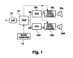
- Fig. 1 is a block diagram showing a configuration of the present embodiment.
- An analog audio signal from various types of sound sources is input by an A/D converter 10.
- the analog audio signal is converted to a digital audio signal, which is input by a DSP 12.
- the digital signal that is output from the A/D converter 10 is, for example, a 24-bit signal.
- various types of processing operations are performed, such as filtering and delay signal superimposition.
- a microcomputer 14 is connected to the DSP 12.
- the microcomputer 14 supplies control signals to the DSP 12 for the various processing operations according to user operation, and the DSP 12 performs the various processing operations on the basis of these control signals.
- the control signals from the microcomputer 14 include a volume signal for controlling the output signal level that is based on volume control operations by the user.
- the DSP 12 performs on the basis of the volume signal a processing operation to adjust the signal level for the digital audio signal that is input. Namely, the DSP 12 attenuates the digital signal by compressing the digital signal in accordance with the amount of attenuation of the audio signal indicated by the volume signal. Namely, attenuation is performed by lowering the value of the digital signal. It should be noted that the number of significant bits decreases after compression. For example, if a 24-bit digital signal is compressed to 16 bits, the result is an attenuation of -48 dB. In the present embodiment, a large attenuation, such as from 0 dB to -48 dB, is not performed at the DSP 12.
- the DSP 12 After performing processing operations including volume adjustment for the digital audio signal, the DSP 12 outputs a digital signal DL for the left channel and a digital signal DR for the right channel.
- the digital signals DL and DR are respectively supplied to D/A converters 16L and 16R, where they are converted to analog signals L and R, then supplied to electronic volume circuits 18L and 18R.
- the electronic volume circuits 18L and 18R perform attenuation for the analog audio signals on the basis of volume signals supplied from the DSP 12. Namely, the DSP 12 performs attenuation through the compression processing of the digital signals in the DSP 12 on a portion of the volume signals supplied from the microcomputer 14 and supplies the volume signals for the remaining attenuation to the electronic volume circuits 18L and 18R. Therefore, the required attenuation is performed in the electronic volume circuits 18L and 18R.
- the electronic volume circuits 18L and 18R can be configured, for example, with resistive potentiometers, to output an analog signal that is attenuated by an amount in accordance with the amount of resistive voltage division. If the level of the analog signal can be adjusted in accordance with the control signal, any form of electronic volume circuit can be employed.
- the attenuation by the electronic volume circuits 18L and 18R only lowers the voltage values with the resistive divider and does not reduce the amount of information by reducing the number of data bits as in digital processing.
- the outputs from the electronic volume circuits 18L and 18R are supplied to speakers 20L and 20R at adjusted volume levels.
- Fig. 2 is a volume-related processing flowchart.
- the DSP 12 first captures (S11) the volume signal from the microcomputer 14.
- various command signals such as for equalization, are received from the microcomputer 14, resulting in the corresponding processing operations to be performed.
- it is judged (S12) whether there is to be a change in the volume signal. If there is to be no change, it is unnecessary to change the volume, and the processing terminates.
- the volume signals generated by the microcomputer sets the maximum attenuation to -80 dB and the number of steps to 82 (1 dB/step, 82 steps for ⁇ ).
- the amount of attenuation in the electronic volume circuits 18L and 18R is set in accordance with the indication in the volume signal and the change up to the set value is performed in 1/5 dB step changes by the DSP 12 (S15).
- the output changes in 1/5 dB increments. As a result, this can prevent noticeably rough sounds from being produced when the volume is varied.
- the amount of attenuation can be changed at a particular timing according to the change in the volume signal and the circuit can be simplified.
- the desired value itself is in 1 dB increments and the amount of attenuation after change is also in 1 dB increments.
- the amount of digital attenuation is changed by the DSP 12 in 1/5 dB increments, and when returning to 0 dB, a 1 dB change is performed at the electronic volume circuits 18L and 18R.
- the data from the DSP 12 is supplied, via D/A converters 16L and 16R and so forth, to the electronic volume circuits 18L and 18R, and on this path a delay is created. Taking this delay into consideration, it is preferable to adjust the timing of the adjustment of the amount of attenuation at the DSP 12 with the adjustment of the amount of attenuation at the electronic volume circuits 18L and 18R.
- the volume adjustment in the present embodiment at -X dB and lower was performed by the digital volume control at the DSP 12.
- the -dB mentioned here is limited to a region of considerably low volume, such as -40 dB or -60 dB. At this region, there is hardly any problem in terms of sound perception even if part of the audio data is lost from compression of the digital signal.
- the analog-based adjustment by the electronic volume circuits 18L and 18R and the digital-based transient fine adjustment by the DSP 12 are combined.
- the digital-based adjustment has an extremely small degradation of information (maximum -1 dB attenuation in the example hereinbefore) and the adjustment is transient.
- the volume is adjusted to the desired value, the amount of attenuation by the DSP 12 is 0 dB. Therefore, there is no degradation of information at all.
- the maximum attenuation is -3/5 dB and the degradation of information can be ignored, it is not necessary for the amount of attenuation for the desired value at the DSP 12 to be 0 dB.
- the fine adjustment portion may be assigned to the DSP 12.
- the change in the amount of attenuation can be performed at an arbitrary timing without performing zero cross detection since the amount of attenuation can be gradually varied in small steps set at the DSP 12.
- the adjustments by the electronic volume circuits 18L and 18R use relatively large steps so that the configuration of the electronic volume circuits 18L and 18R can be simplified. For example, in the case using resistive voltage division, when the range of 0 to 40 dB is adjusted in 1/5 dB steps, 200 resistors are necessary. However, if adjusted in 1 dB steps, only 40 resistors are sufficient.
- the 5 step adjustments of 0, -1/5, -2/5, - 3/5, and -4/5 dB are repeated within 1 dB as shown in Fig. 4. Then, from -X dB to - ⁇ , the amount of attenuation increases in 1/5 dB increments. In the transitional period of the volume change, the attenuation adjustment in the DSP 12 is performed.
- both the digital processing in the DSP 12 and the analog processing in the electronic volume circuits 18L and 18R are combined.
- the signal levels in the electronic volume circuits 18L and 18R are varied in 1 dB increments whereas the signal level is varied in 1/5 dB increments by the DSP 12 when changing the volume. Therefore, the volume changes in 1/5 dB steps as shown in Fig. 6.
Description
- The present invention relates to a level adjustment circuit for adjusting the signal level of an audio signal, and more particularly for performing both digital level adjustment and analog level adjustment.
- Heretofore, it was necessary to vary the output level in audio equipment, such as from a speaker, and an electronic volume control was thus employed to adjust the output signal level in accordance with a volume control knob or volume control button. The electronic volume control adjusts the signal level of the analog audio signal by analog processing in accordance with a volume signal generated from user operation.
- On the other hand, in the processing of audio signals, a DSP (digital signal processor) is used to perform digital processing, such as for equalization and sound field correction. In this type of DSP-based digital processing, it is also possible to perform signal level adjustment, and the level adjustment is performed by digital processing in accordance with the volume signal.
- In this manner, either analog processing or digital processing was employed in the past to adjust the audio signal level in accordance with the volume signal. The present applicant proposed in Japanese Patent Application No. Hei 10-278008 (not publicly known at the time of filing) an invention relating to a hybrid volume combining level adjustment based on analog processing and level adjustment based on digital processing. The technique of this application combines digital processing and analog processing in such a way that after an adjustment is performed by digital processing, analog processing is performed in case further adjustment is required. In this manner, a preferable level adjustment can be performed by combining the characteristics of analog processing and digital processing.
- WO 99/17442 describes a system in which an analog volume attenuator is used to attenuate an audio signal above a threshold value and a digital volume control is used to attenuate an audio signal below the threshold.
- JP09153748 describes a system in which a digital attenuator attenuates an inputted audio signal with an analog attenuator further attenuating the signal.
- However, various techniques can be devised in combining analog processing and digital processing, and the preceding proposed technique is not necessarily preferable.
- Furthermore, when adjusting the volume in this type of circuit, zero cross was detected and the amount of attenuation was varied at the time to prevent noticeably rough sounds from being produced. For this reason, a problem was that the circuit became complex due to the need for comparators and other circuit elements.
- In accordance with an aspect of the present invention there is provided a level adjustment circuit according to the accompanying claims.
- The object of the present invention is to provide a level adjustment circuit capable of performing more preferable level adjustments by combining digital processing and analog processing.
- In the present invention, level adjustment is performed by digital processing for a predetermined low level. Although the level adjustment based on digital processing causes the amount of information to decrease due to data compression, the small amount of data at low level regions hardly poses a problem so that the adjustment by digital processing can be performed without problems. Furthermore, since part of the level adjustment is performed through digital processing, it is possible to decrease the number of steps for the level adjustment by analog processing, and thus simplify the configuration of the analog level adjustment circuit.
- Furthermore, in another mode, when varying the level, the level is gradually varied in small steps by digital processing. Therefore, noticeably rough sounds are hardly produced when varying the level, and level changes can be performed even when outside the zero cross point. A circuit for zero cross detection becomes unnecessary thereby enabling the circuit configuration to be simplified.
- As described hereinbefore, according to the present embodiment, level adjustment is performed by digital processing for a predetermined low level. Although the level adjustment based on digital processing causes the amount of information to decrease due to data compression, the small amount of data at low level regions hardly poses a problem so that the adjustment by digital processing can be performed without problems. Furthermore, since part of the level adjustment is performed through digital processing, it is possible to decrease the number of steps for the level adjustment by analog processing, and thus simplify the configuration of the analog level adjustment circuit.
- Furthermore, when varying the level, the level is gradually varied in small steps by digital processing. Therefore, noticeably rough sounds are hardly produced when varying the level, and level changes can be performed even when outside the zero cross point. A circuit for zero cross detection becomes unnecessary thereby enabling the circuit configuration to be simplified.
-
- Fig. 1 shows a configuration of the present embodiment.
- Fig. 2 is a flowchart illustrating an operation of the embodiment.
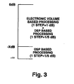
- Fig. 3 illustrates a control technique.
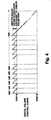
- Fig. 4 illustrates an adjustment based on a digital volume control.
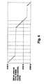
- Fig. 5 illustrates an adjustment based on an analog volume control.
- Fig. 6 illustrates an adjustment based on digital and analog volume control.
- A preferred embodiment of the present invention will be described hereinafter with reference to the drawings.
- Fig. 1 is a block diagram showing a configuration of the present embodiment. An analog audio signal from various types of sound sources is input by an A/
D converter 10. At the A/D converter 10, the analog audio signal is converted to a digital audio signal, which is input by aDSP 12. The digital signal that is output from the A/D converter 10 is, for example, a 24-bit signal. At theDSP 12, various types of processing operations are performed, such as filtering and delay signal superimposition. Amicrocomputer 14 is connected to the DSP 12. Themicrocomputer 14 supplies control signals to theDSP 12 for the various processing operations according to user operation, and theDSP 12 performs the various processing operations on the basis of these control signals. - The control signals from the
microcomputer 14 include a volume signal for controlling the output signal level that is based on volume control operations by the user. The DSP 12 performs on the basis of the volume signal a processing operation to adjust the signal level for the digital audio signal that is input. Namely, the DSP 12 attenuates the digital signal by compressing the digital signal in accordance with the amount of attenuation of the audio signal indicated by the volume signal. Namely, attenuation is performed by lowering the value of the digital signal. It should be noted that the number of significant bits decreases after compression. For example, if a 24-bit digital signal is compressed to 16 bits, the result is an attenuation of -48 dB. In the present embodiment, a large attenuation, such as from 0 dB to -48 dB, is not performed at theDSP 12. - After performing processing operations including volume adjustment for the digital audio signal, the
DSP 12 outputs a digital signal DL for the left channel and a digital signal DR for the right channel. The digital signals DL and DR are respectively supplied to D/A converters electronic volume circuits - The
electronic volume circuits DSP 12. Namely, theDSP 12 performs attenuation through the compression processing of the digital signals in theDSP 12 on a portion of the volume signals supplied from themicrocomputer 14 and supplies the volume signals for the remaining attenuation to theelectronic volume circuits electronic volume circuits - The
electronic volume circuits - The attenuation by the
electronic volume circuits - The outputs from the
electronic volume circuits speakers - Fig. 2 is a volume-related processing flowchart. The
DSP 12 first captures (S11) the volume signal from themicrocomputer 14. In practice, various command signals, such as for equalization, are received from themicrocomputer 14, resulting in the corresponding processing operations to be performed. Then, it is judged (S12) whether there is to be a change in the volume signal. If there is to be no change, it is unnecessary to change the volume, and the processing terminates. - If the result in S12 is YES, it is judged (S13) whether the desired volume value after the change is lower than -X dB (for example X=40 or 60). If the result of this judgment is YES, signals for setting the amount of attenuation to a maximum (-S dB) are sent to the
electronic volume circuits - For example, suppose the volume signals generated by the microcomputer sets the maximum attenuation to -80 dB and the number of steps to 82 (1 dB/step, 82 steps for ∞). In this case, for example, where X=40 (or 60), the amount of attenuation at the
DSP 12 is set, for example, to 1 step = 1/5 dB. - If the result in S13 is NO, the amount of attenuation in the
electronic volume circuits - Without performing zero cross detection and so forth, the amount of attenuation can be changed at a particular timing according to the change in the volume signal and the circuit can be simplified.
- The desired value itself is in 1 dB increments and the amount of attenuation after change is also in 1 dB increments. In the case of a large change, the amount of digital attenuation is changed by the
DSP 12 in 1/5 dB increments, and when returning to 0 dB, a 1 dB change is performed at theelectronic volume circuits - The data from the
DSP 12 is supplied, via D/A converters electronic volume circuits DSP 12 with the adjustment of the amount of attenuation at theelectronic volume circuits - In this manner, as shown in Fig. 3, the volume adjustment in the present embodiment at -X dB and lower was performed by the digital volume control at the
DSP 12. The -dB mentioned here is limited to a region of considerably low volume, such as -40 dB or -60 dB. At this region, there is hardly any problem in terms of sound perception even if part of the audio data is lost from compression of the digital signal. - On the other hand, in the range from 0 to X dB, the analog-based adjustment by the
electronic volume circuits DSP 12 are combined. As a result, since the range is considerably small, the digital-based adjustment has an extremely small degradation of information (maximum -1 dB attenuation in the example hereinbefore) and the adjustment is transient. When the volume is adjusted to the desired value, the amount of attenuation by theDSP 12 is 0 dB. Therefore, there is no degradation of information at all. - However, since the maximum attenuation is -3/5 dB and the degradation of information can be ignored, it is not necessary for the amount of attenuation for the desired value at the
DSP 12 to be 0 dB. - Furthermore, in a system where the desired value is subdivided, the fine adjustment portion may be assigned to the
DSP 12. - In any case, when varying the volume, the change in the amount of attenuation can be performed at an arbitrary timing without performing zero cross detection since the amount of attenuation can be gradually varied in small steps set at the
DSP 12. - Furthermore, the adjustments by the
electronic volume circuits electronic volume circuits - For the volume adjustment in the present embodiment up to -X dB in the
DSP 12, the 5 step adjustments of 0, -1/5, -2/5, - 3/5, and -4/5 dB are repeated within 1 dB as shown in Fig. 4. Then, from -X dB to -∞, the amount of attenuation increases in 1/5 dB increments. In the transitional period of the volume change, the attenuation adjustment in theDSP 12 is performed. - On the other hand, as shown in Fig. 5, the amount of attenuation in the
electronic volume circuits - In the apparatus of the present embodiment, both the digital processing in the
DSP 12 and the analog processing in theelectronic volume circuits electronic volume circuits DSP 12 when changing the volume. Therefore, the volume changes in 1/5 dB steps as shown in Fig. 6. - While there has been described what are at present considered to be preferred embodiments of the invention, it will be understood that various modifications may be made thereto, and it is intended that the appended claims cover all such modifications as fall within the scope of the invention.
Claims (2)
- A level adjustment circuit for adjusting the signal level of an audio signal, the level adjustment circuit comprising:a digital level adjustment circuit (12) for performing level adjustments by processing digital audio signals;a D/A conversion circuit (16L, 16R) for converting digital audio signals to analog audio signals; andan analog level adjustment circuit (18L, 18R) for performing level adjustments by processing obtained analog audio signals;wherein a level adjustment step in the digital level adjustment circuit (12) is set smaller than a level adjustment step in the analog level adjustment circuit (18L, 18R), and
wherein level adjustments are performed by combining adjustments by the larger steps of the analog level adjustment circuit (18L, 18R) and adjustments by the smaller steps of the digital level adjustment circuit (12) within the larger steps of the analog level adjustment circuit (18L, 18R) when a volume signal indicating a desired output level for audio signals indicates a level exceeding a predetermined low level set value; and
level adjustments over a range exceeding the large steps of the analog level adjustment circuit (18L, 18R) are performed by the digital level adjustment circuit alone when the volume signal indicates a desired output level that is lower than or equal to the predetermined low level set value;
wherein, when the volume signal indicates a level exceeding the predetermined low level set value, every time a change corresponding to a large step by the analog level adjustment circuit (18L, 18R) is made by small steps by the digital level adjustment circuit (12), a step by the analog level adjustment circuit (18L, 18R) is changed and an amount of adjustment by the digital level adjustment circuit (12) is reset, so that level adjustments to the output level indicated by the volume signal are performed by changes in small steps made by the digital level adjustment circuit (12). - A level adjustment circuit according to claim 1, wherein, when the volume signal indicates a high level exceeding the predetermined low level set value, an amount of adjustment by the digital level adjustment circuit (12) is set to 0 to obtain a final output level so that the level adjustments performed by the digital level adjustment circuit (12) is used only in a transitional state.
Applications Claiming Priority (2)
| Application Number | Priority Date | Filing Date | Title |
|---|---|---|---|
| JP2000094331A JP3889546B2 (en) | 2000-03-30 | 2000-03-30 | Level adjustment circuit |
| JP2000094331 | 2000-03-30 |
Publications (3)
| Publication Number | Publication Date |
|---|---|
| EP1148637A2 EP1148637A2 (en) | 2001-10-24 |
| EP1148637A3 EP1148637A3 (en) | 2003-09-10 |
| EP1148637B1 true EP1148637B1 (en) | 2007-05-09 |
Family
ID=18609396
Family Applications (1)
| Application Number | Title | Priority Date | Filing Date |
|---|---|---|---|
| EP01303007A Expired - Lifetime EP1148637B1 (en) | 2000-03-30 | 2001-03-29 | Level adjustment circuit |
Country Status (7)
| Country | Link |
|---|---|
| US (1) | US7110557B2 (en) |
| EP (1) | EP1148637B1 (en) |
| JP (1) | JP3889546B2 (en) |
| KR (1) | KR100496373B1 (en) |
| CN (1) | CN1332519A (en) |
| DE (1) | DE60128289T2 (en) |
| TW (1) | TW515994B (en) |
Families Citing this family (19)
| Publication number | Priority date | Publication date | Assignee | Title |
|---|---|---|---|---|
| US20060014697A1 (en) | 2001-08-22 | 2006-01-19 | Travis Mickle | Pharmaceutical compositions for prevention of overdose or abuse |
| JP3526850B2 (en) * | 2002-03-26 | 2004-05-17 | 沖電気工業株式会社 | Audio output device |
| US7539614B2 (en) * | 2003-11-14 | 2009-05-26 | Nxp B.V. | System and method for audio signal processing using different gain factors for voiced and unvoiced phonemes |
| US20070206820A1 (en) * | 2004-03-19 | 2007-09-06 | Pioneer Corporation | Volume Control Method, Volume Controller, Volume Control Program, Electronic Apparatus |
| US20070189544A1 (en) * | 2005-01-15 | 2007-08-16 | Outland Research, Llc | Ambient sound responsive media player |
| JPWO2006106672A1 (en) * | 2005-03-31 | 2008-09-11 | パイオニア株式会社 | Amplification device and information processing device |
| US20060247811A1 (en) * | 2005-05-02 | 2006-11-02 | Texas Instruments Incorporated | Batch processing control of volume events in a digital amplifier environment |
| CN1953047B (en) * | 2005-10-21 | 2010-06-23 | 英华达(南京)科技有限公司 | Control system of volume range and method thereof |
| KR100857086B1 (en) * | 2006-10-09 | 2008-09-05 | 엘지전자 주식회사 | Method for setting audio volume level |
| US8135147B2 (en) * | 2006-10-09 | 2012-03-13 | Lg Electronics Inc. | Method and device for adjusting audio volume level |
| JP4948202B2 (en) * | 2007-02-23 | 2012-06-06 | アルパイン株式会社 | Audio output device, control program, and computer-readable recording medium |
| WO2008146189A2 (en) * | 2007-05-30 | 2008-12-04 | Nxp B.V. | Audio signal amplification |
| CN101350604B (en) * | 2007-07-19 | 2012-07-04 | 鸿富锦精密工业(深圳)有限公司 | Apparatus and method for automatically switching volume control mode |
| DK2346271T3 (en) * | 2009-12-01 | 2014-08-04 | Oticon As | Control of operating parameters in a binaural listening system |
| JP2011160031A (en) * | 2010-01-29 | 2011-08-18 | Ricoh Co Ltd | Sound and music reproduction device |
| DE102010036207A1 (en) * | 2010-08-31 | 2012-03-01 | Siemens Aktiengesellschaft | Switch i.e. power switch for low voltages, has device for parameterization of triggering unit adapted to adjust digital resistance potentiometer at digital resistance value, which is corresponding to rated currents of switch |
| CN104242848B (en) * | 2013-06-21 | 2016-12-28 | 普诚科技股份有限公司 | The method of gain control system, sound playing system and gain control thereof |
| JP7106913B2 (en) * | 2018-03-22 | 2022-07-27 | ヤマハ株式会社 | AUDIO EQUIPMENT, AUDIO CONTROL SYSTEM, AUDIO CONTROL METHOD, AND PROGRAM |
| CN113747309A (en) * | 2020-05-27 | 2021-12-03 | 阿里巴巴集团控股有限公司 | Audio processing method, link and equipment |
Family Cites Families (8)
| Publication number | Priority date | Publication date | Assignee | Title |
|---|---|---|---|---|
| US5323275A (en) * | 1991-01-31 | 1994-06-21 | Sony Corporation | Digital signal recording and/or reproducing apparatus having correlated digital and analog signal level controllers |
| JPH05198092A (en) | 1992-01-20 | 1993-08-06 | Sony Corp | Level control circuit |
| US5394476A (en) * | 1992-12-17 | 1995-02-28 | Motorola, Inc. | Volume control device |
| JPH07240647A (en) | 1994-02-28 | 1995-09-12 | Fujitsu Ten Ltd | Sound reproducing circuit |
| GB2297443B (en) | 1995-01-26 | 1999-09-08 | Sony Uk Ltd | Amplifier |
| JPH09153748A (en) | 1995-11-30 | 1997-06-10 | Sharp Corp | Sound volume varying device |
| US6317502B1 (en) * | 1996-02-29 | 2001-11-13 | Sanyo Electric Co., Ltd. | Electronic volume control circuit with controlled output characteristic |
| US6088461A (en) | 1997-09-26 | 2000-07-11 | Crystal Semiconductor Corporation | Dynamic volume control system |
-
2000
- 2000-03-30 JP JP2000094331A patent/JP3889546B2/en not_active Expired - Fee Related
-
2001
- 2001-03-12 TW TW090105716A patent/TW515994B/en not_active IP Right Cessation
- 2001-03-26 US US09/818,249 patent/US7110557B2/en not_active Expired - Lifetime
- 2001-03-29 EP EP01303007A patent/EP1148637B1/en not_active Expired - Lifetime
- 2001-03-29 KR KR10-2001-0016468A patent/KR100496373B1/en not_active IP Right Cessation
- 2001-03-29 DE DE60128289T patent/DE60128289T2/en not_active Expired - Lifetime
- 2001-03-30 CN CN01117886A patent/CN1332519A/en active Pending
Also Published As
| Publication number | Publication date |
|---|---|
| JP3889546B2 (en) | 2007-03-07 |
| US20010026624A1 (en) | 2001-10-04 |
| DE60128289T2 (en) | 2008-01-10 |
| JP2001285983A (en) | 2001-10-12 |
| EP1148637A2 (en) | 2001-10-24 |
| KR20010095091A (en) | 2001-11-03 |
| TW515994B (en) | 2003-01-01 |
| KR100496373B1 (en) | 2005-06-21 |
| CN1332519A (en) | 2002-01-23 |
| DE60128289D1 (en) | 2007-06-21 |
| EP1148637A3 (en) | 2003-09-10 |
| US7110557B2 (en) | 2006-09-19 |
Similar Documents
| Publication | Publication Date | Title |
|---|---|---|
| EP1148637B1 (en) | Level adjustment circuit | |
| US6252969B1 (en) | Howling detection and prevention circuit and a loudspeaker system employing the same | |
| US5255324A (en) | Digitally controlled audio amplifier with voltage limiting | |
| US7706552B2 (en) | Sound signal processing apparatus and sound signal processing method | |
| US4908855A (en) | Electronic telephone terminal having noise suppression function | |
| KR100744847B1 (en) | Input apparatus, reproducing apparatus and volume adjusting method | |
| US8611572B2 (en) | Device and method for controlling the step size of an adaptive filter | |
| US7315625B2 (en) | Sound apparatus, method of changing sound characteristics, and data recording medium on which a sound correction program | |
| KR930001295B1 (en) | Gain controller | |
| US20110200209A1 (en) | Level adjusting circuit | |
| US10630252B2 (en) | Audio signal processor and method of processing audio signal | |
| EP1312168B1 (en) | Method and circuit for regulating the signal level fed to an analog-digital converter | |
| JP2946884B2 (en) | Low frequency response correction circuit | |
| EP1263132B1 (en) | Variable signal attenuating circuit | |
| JPS61278217A (en) | Fm stereo receiver | |
| KR19990041228A (en) | Automatic volume control for audio equipment with equalization | |
| JP3815836B2 (en) | Audio signal amplifier circuit | |
| US20050141732A1 (en) | Amplifying apparatus | |
| JPH0519843B2 (en) | ||
| JPH0256155A (en) | Howling preventing device | |
| JP3202902B2 (en) | Noise suppression device | |
| JPH09284073A (en) | Automatic gain control circuit | |
| JPH0646490A (en) | Howling preventing processor | |
| JPH03128511A (en) | Automatic mixer | |
| JPH06310963A (en) | Tone controller |
Legal Events
| Date | Code | Title | Description |
|---|---|---|---|
| PUAI | Public reference made under article 153(3) epc to a published international application that has entered the european phase |
Free format text: ORIGINAL CODE: 0009012 |
|
| AK | Designated contracting states |
Kind code of ref document: A2 Designated state(s): AT BE CH CY DE DK ES FI FR GB GR IE IT LI LU MC NL PT SE TR |
|
| AX | Request for extension of the european patent |
Free format text: AL;LT;LV;MK;RO;SI |
|
| RIN1 | Information on inventor provided before grant (corrected) |
Inventor name: UCHINO, TAKASHI Inventor name: MASUMOTO, TAKAHIKO Inventor name: KON, YSHIHIKO Inventor name: KANEKO, HIROSHI |
|
| PUAL | Search report despatched |
Free format text: ORIGINAL CODE: 0009013 |
|
| AK | Designated contracting states |
Kind code of ref document: A3 Designated state(s): AT BE CH CY DE DK ES FI FR GB GR IE IT LI LU MC NL PT SE TR |
|
| AX | Request for extension of the european patent |
Extension state: AL LT LV MK RO SI |
|
| 17P | Request for examination filed |
Effective date: 20040301 |
|
| AKX | Designation fees paid |
Designated state(s): DE FR GB IT NL |
|
| 17Q | First examination report despatched |
Effective date: 20040804 |
|
| GRAP | Despatch of communication of intention to grant a patent |
Free format text: ORIGINAL CODE: EPIDOSNIGR1 |
|
| RIN1 | Information on inventor provided before grant (corrected) |
Inventor name: KON, YOSHIHIKO Inventor name: MASUMOTO, TAKAHIKO Inventor name: KANEKO, HIROSHI Inventor name: UCHINO, TAKASHI |
|
| GRAS | Grant fee paid |
Free format text: ORIGINAL CODE: EPIDOSNIGR3 |
|
| GRAA | (expected) grant |
Free format text: ORIGINAL CODE: 0009210 |
|
| AK | Designated contracting states |
Kind code of ref document: B1 Designated state(s): DE FR GB IT NL |
|
| REG | Reference to a national code |
Ref country code: GB Ref legal event code: FG4D |
|
| RIN1 | Information on inventor provided before grant (corrected) |
Inventor name: KON, YOSHIHIKO Inventor name: MASUMOTO, TAKAHIKO Inventor name: KANEKO, HIROSHI Inventor name: UCHINO, TAKASHI |
|
| REF | Corresponds to: |
Ref document number: 60128289 Country of ref document: DE Date of ref document: 20070621 Kind code of ref document: P |
|
| ET | Fr: translation filed | ||
| PLBE | No opposition filed within time limit |
Free format text: ORIGINAL CODE: 0009261 |
|
| STAA | Information on the status of an ep patent application or granted ep patent |
Free format text: STATUS: NO OPPOSITION FILED WITHIN TIME LIMIT |
|
| 26N | No opposition filed |
Effective date: 20080212 |
|
| PGFP | Annual fee paid to national office [announced via postgrant information from national office to epo] |
Ref country code: FR Payment date: 20120328 Year of fee payment: 12 |
|
| PGFP | Annual fee paid to national office [announced via postgrant information from national office to epo] |
Ref country code: GB Payment date: 20120227 Year of fee payment: 12 Ref country code: IT Payment date: 20120323 Year of fee payment: 12 |
|
| PGFP | Annual fee paid to national office [announced via postgrant information from national office to epo] |
Ref country code: DE Payment date: 20120330 Year of fee payment: 12 Ref country code: NL Payment date: 20120322 Year of fee payment: 12 |
|
| REG | Reference to a national code |
Ref country code: NL Ref legal event code: V1 Effective date: 20131001 |
|
| GBPC | Gb: european patent ceased through non-payment of renewal fee |
Effective date: 20130329 |
|
| REG | Reference to a national code |
Ref country code: FR Ref legal event code: ST Effective date: 20131129 |
|
| REG | Reference to a national code |
Ref country code: DE Ref legal event code: R119 Ref document number: 60128289 Country of ref document: DE Effective date: 20131001 |
|
| PG25 | Lapsed in a contracting state [announced via postgrant information from national office to epo] |
Ref country code: FR Free format text: LAPSE BECAUSE OF NON-PAYMENT OF DUE FEES Effective date: 20130402 Ref country code: GB Free format text: LAPSE BECAUSE OF NON-PAYMENT OF DUE FEES Effective date: 20130329 Ref country code: DE Free format text: LAPSE BECAUSE OF NON-PAYMENT OF DUE FEES Effective date: 20131001 |
|
| PG25 | Lapsed in a contracting state [announced via postgrant information from national office to epo] |
Ref country code: IT Free format text: LAPSE BECAUSE OF NON-PAYMENT OF DUE FEES Effective date: 20130329 Ref country code: NL Free format text: LAPSE BECAUSE OF NON-PAYMENT OF DUE FEES Effective date: 20131001 |