CN1599552B - Electronic component mounting device - Google Patents
Electronic component mounting device Download PDFInfo
- Publication number
- CN1599552B CN1599552B CN 200410079776 CN200410079776A CN1599552B CN 1599552 B CN1599552 B CN 1599552B CN 200410079776 CN200410079776 CN 200410079776 CN 200410079776 A CN200410079776 A CN 200410079776A CN 1599552 B CN1599552 B CN 1599552B
- Authority
- CN
- China
- Prior art keywords
- circuit board
- electronic component
- circuit boards
- circuit
- component mounting
- Prior art date
- Legal status (The legal status is an assumption and is not a legal conclusion. Google has not performed a legal analysis and makes no representation as to the accuracy of the status listed.)
- Expired - Fee Related
Links
Images


Landscapes
- Supply And Installment Of Electrical Components (AREA)
Abstract
一种电子部件安装装置,在尺寸小的电路板上装载电子部件时也能高效率地进行电子部件的装载,具有:能够放置多个电路板的电路板输送轨道;设置在输送轨道上的检测电路板块数的传感器;通过来自传感器的信号固定电路板的定位部;被设置在输送轨道之间的可以移动的电路板挡块;配置在所述电路板输送轨道附近的用于供给将被装载在所述电路板上的部件的部件供给部;设置在所述电路板输送轨道的上方并在下端部具有吸附所述部件的喷管的安装头,其在所述多块电路板上可以装载电子部件。
An electronic component mounting device capable of efficiently loading electronic components even when electronic components are loaded on a small-sized circuit board has: a circuit board conveying track capable of placing a plurality of circuit boards; a detection device installed on the conveying track A sensor for the number of circuit boards; a positioning part for fixing the circuit board by a signal from the sensor; a movable circuit board stopper arranged between the conveying tracks; The component supply part of the components on the circuit board; the installation head that is arranged above the circuit board conveying track and has a nozzle that absorbs the components at the lower end, and can be loaded on the plurality of circuit boards electronic components.
Description
技术领域technical field
本发明涉及在电路板上装载电子部件的电子部件安装装置。The present invention relates to an electronic component mounting device for mounting electronic components on a circuit board.
背景技术Background technique
在以往的这种电子部件安装装置中,对一块电路板装载电子部件,如果该板的装载结束,则下一张电路板被输送到电路板装载位置,在该位置再次进行电子部件的装载。In such a conventional electronic component mounting apparatus, electronic components are loaded on one circuit board, and when the loading of the board is completed, the next circuit board is conveyed to the circuit board loading position, and the electronic components are loaded again at this position.
由于电子板的尺寸大小不一,所以在电路板的尺寸小的情况下,装载范围也变小,而对于在大的电路板上装载大量部件的传送带等部件供给部来说,电子部件的吸附喷管的移动范围变大,并且每块电路板的输送时间更长,存在不能加快生产节奏而降低生产率的问题。Due to the different sizes of electronic boards, the loading range becomes smaller when the size of the board is small, and for parts supply parts such as conveyor belts that load a large number of parts on a large board, the adsorption of electronic parts is difficult. The range of movement of the nozzle becomes larger, and the conveyance time per board is longer, and there is a problem that the production rate cannot be accelerated and the productivity is lowered.
因此,如日本特开平6-342999号方案,提出了根据电路板的大小来控制电路板的电子部件的装载位置,缩短输送头的移动行程,高速而高效地将电子部件装载在电路板上的安装方法。Therefore, such as Japanese Patent Application No. 6-342999, it is proposed to control the loading position of the electronic components of the circuit board according to the size of the circuit board, shorten the moving stroke of the delivery head, and efficiently load the electronic components on the circuit board at a high speed. installation method.
专利文献1:特开平6-342999号公报Patent Document 1: JP-A-6-342999
发明内容Contents of the invention
然而,上述文献1所述的安装方法是在每块电路板上装载电子部件,存在将电路板送入送出时耗费时间,提高装载效率受限的问题。However, the mounting method described in the above-mentioned document 1 is to mount electronic components on each circuit board, and there is a problem that it takes time to carry the circuit boards in and out, and there is a limitation in improving the loading efficiency.
为了解决上述问题,本发明提供了一种在尺寸小的电路板上装载电子部件时也能高效率作业的电子部件安装装置。In order to solve the above-mentioned problems, the present invention provides an electronic component mounting device that can work efficiently even when electronic components are mounted on a small-sized circuit board.
为了达到上述目的,权利要求1中记载的电子部件安装装置具有:能够放置多个电路板的电路板输送轨道;被设置在输送轨道上的用于检测电路板数量的传感器装置;通过来自传感器装置的信号以固定电路板的定位部;被设置在输送轨道之间可以移动的电路板挡块;配置在所述电路板输送轨道附近的用于供给装载在所述电路板上的部件的部件供给部;被设置在所述电路板输送轨道的上方并在下端部具有吸附所述部件的喷管(nozzle)的安装头,从而形成在所述多个电路板上装载电子部件的结构。In order to achieve the above object, the electronic component mounting device described in claim 1 has: a circuit board conveying rail capable of placing a plurality of circuit boards; a sensor device for detecting the number of circuit boards arranged on the conveying rail; The signal to fix the positioning part of the circuit board; the circuit board stopper that is arranged to be movable between the conveying tracks; the component supply that is arranged near the circuit board conveying track for supplying the components loaded on the circuit board a mounting head that is disposed above the circuit board conveying rail and has a nozzle that absorbs the components at a lower end, thereby forming a structure for loading electronic components on the plurality of circuit boards.
该实施方式的电子部件安装装置,其定位部使多个电路板能够固定定位在电路板输送传送器上,同时,通过传感器装置算出规定多个电路板的总数,将多个电路板看作是一张电路板来进行部件的装载,所以,能够减少输送时间的损耗,减少了生产间歇(tact)并且降低了生产成本。In the electronic component mounting device of this embodiment, the positioning unit enables a plurality of circuit boards to be fixedly positioned on the circuit board conveyance conveyor, and at the same time, the sensor device calculates the total number of the predetermined plurality of circuit boards, and regards the plurality of circuit boards as One circuit board is used for loading parts, so the loss of transportation time can be reduced, the production tact can be reduced, and the production cost can be reduced.
附图说明Description of drawings
图1是本发明实施方式的电子部件安装装置的切去一部分的斜视图。FIG. 1 is a partially cutaway perspective view of an electronic component mounting device according to an embodiment of the present invention.
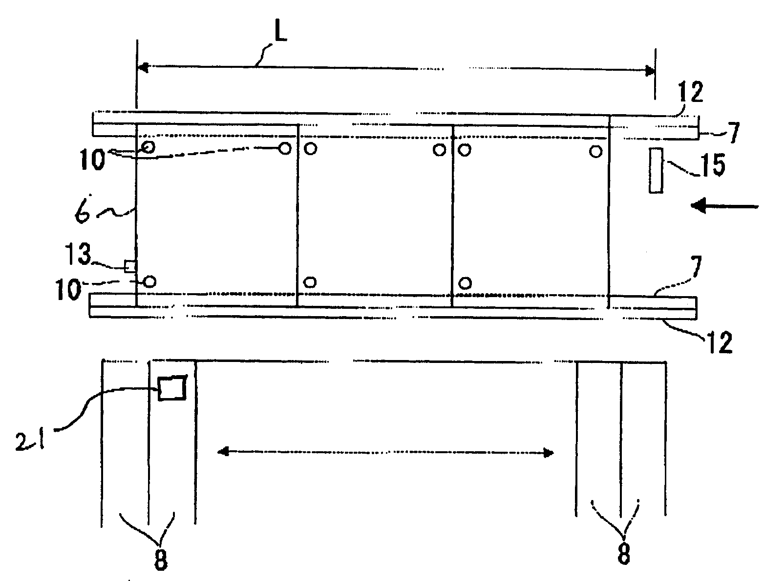
图2是表示本发明实施方式的电子部件安装装置的输送路线的主要部分结构的俯视图。FIG. 2 is a plan view showing the configuration of main parts of the conveyance line of the electronic component mounting apparatus according to the embodiment of the present invention.
图3是本发明实施方式的电子部件安装装置的方框图的一部分。3 is a part of a block diagram of the electronic component mounting apparatus according to the embodiment of the present invention.
符号说明Symbol Description
6电路板;7电路板输送轨道;15传感器;12定位部;13挡块;8部件供给部;5安装头;11电路板识别摄像机;20控制部;22识别装置;23存储装置。6 circuit board; 7 circuit board conveying track; 15 sensor; 12 positioning part; 13 block; 8 component supply part;
具体实施方式Detailed ways
下面对本发明的电子部件安装装置的实施方式进行说明。Embodiments of the electronic component mounting apparatus of the present invention will be described below.
图1是该实施方式的电子部件安装装置1的简略整体图。如图1所示,电子部件安装装置1具有:基台2;安装在基台2上的Y方向驱动装置3、3;熔合Y方向驱动装置3、3并使其可以移动的X方向驱动装置4;设置在X方向驱动装置4上并可以移动的安装头5。FIG. 1 is a schematic overall view of an electronic component mounting apparatus 1 according to this embodiment. As shown in FIG. 1 , the electronic component mounting apparatus 1 has: a base 2; Y-direction driving devices 3, 3 mounted on the base 2; 4; a movable mounting head 5 arranged on the X-direction driving device 4 .
在所述基台2上配置有输送电路板6用的电路板输送传送器(conveyer)7和由多个传送带构成的电子部件供给装置8,电子部件供给装置8以夹着该电路板输送传送带7的侧面或电路板输送传送器(conveyer)7的状态,向前后两侧供给电子部件。如图3所示,通过控制部20所述安装头5由以下几个部件组成,包括:驱动Y方向驱动装置3的Y轴电机25;驱动X方向驱动装置4的X轴电机24;在下端吸附电子部件用的喷管9;使所述喷管9上下移动的驱动装置(Z轴电机26);使所述喷管9旋转的驱动装置(θ轴电机27);识别电路板标记10用的电路板识别摄像机11;未图示的照明装置。On the base 2, a circuit board conveying conveyor (conveyer) 7 for conveying the
并且,图2的L表示安装头5的喷管9的移动范围。In addition, L in FIG. 2 indicates the moving range of the nozzle pipe 9 of the mounting head 5 .
所述电路板输送传送器7被配置成向左右方向(X轴方向)延伸,以使所述电路板6从右端部的送入位置输送到左端部的送出位置。并且,在所述电路板输送传送器7上设置了用于定位电路板6的定位夹紧(clamp)部件(定位部)12。定位夹紧部件12被配置在电路板6的输送路线两侧,如果产生后述检测信号,将通过电气驱动装置(未图示)的动作夹紧电路板6并于该位置固定。13是被设置在电路板输送传送器7之间的气缸(air cylinder)或者是由电磁线圈(solenoid)构成的挡块,其在电路板6的输送路线上移动,相对电路板6的输送方向使电路板停止。于是,电路板6被支承在这些位置的时候,可以通过安装头5进行作业。The circuit board transport conveyor 7 is arranged to extend in the left-right direction (X-axis direction) so that the
部件识别摄像机14被设置在所述基台2的电路板输送传送器7和电子部件供给装置8之间,来识别所述安装头5的喷管9吸附着的电子部件21的形状及位置。The
传感器15被设置在电路板输送传送器7的右端部的电路板送入位置,如果电路板6遮盖了传感器15,则产生检测信号,该检测信号被传送给可检测电路板的送入块数的控制部20的同时通过电路板,检测信号消失,则根据该信号产生和结束判断得知电路板被送入一块,同时被控制部20计数。The
并且,累计每一块装载电子部件的电路板6,如果送入的块数达到了规定数,则将电路板输送传送器7的送入动作暂时停止,使定位部12动作并固定达到规定块数的电路板6,然后启动对应规定块数的生产程序,进行电子部件21在电路板上的装载动作。And, add up each
另外,在送入的电路板为一块以上且不足三块的情况时,即使经过一定的时间传感器15也不产生检测信号,但是通过监视器30表示该情况,可选择自动启动或操作者用启动开关(鼠标29)或操作键盘28输入指令,以开始进行部件装载。In addition, when the number of circuit boards sent in is more than one and less than three, the
并且,所述规定块数的电路板的送入块数的确定是通过在事先被存储装置23所存储的生产程序中输入电路板的输送方向的长度,从而计算出在喷管的移动范围L内可送入的块数。And, the determination of the number of incoming circuit boards of the specified number is to calculate the moving range L of the nozzle by inputting the length of the conveying direction of the circuit boards in the production program stored in the
下面说明上述结构的动作。Next, the operation of the above configuration will be described.
首先,第1块电路板6从图2的右端通过电路板输送传送器7沿箭头方向送入,接触挡块(电路板挡块)13后定位。然后,第2块电路板6被送入,接触第1块电路板6后定位,其后,第3块电路板6被送入,接触第2块电路板6后停止。如果第3块电路板6通过传感器15时,从传感器15产生信号,则根据该信号停止送入动作,送入的3块电路板6被定位部12夹紧并固定位置。First, the
同时,安装头5移动到电路板6上,通过电路板识别摄像机11来识别被分别设置在多个电路板6上的电路板标记。Simultaneously, the mounting head 5 moves onto the
然后,安装头5移动到部件供给装置8上,吸附来自各传送带的电子部件。接着,安装头5吸附电子部件移动到部件识别摄像机14的上部,通过识别装置22对被吸附的电子部件的形状及位置进行识别。所述电子部件的形状及位置的识别通过识别装置22完成后,识别结果被传送到控制部20,安装头5根据控制部20要求修正对应各块电路板的电子部件的装载位置,并将电子部件装载在3块电路板上。预定的部件装载作业结束之后,电路板输送传送器7将完成作业的3块电路板送到如图1所示的左侧。继而将新送入的电路板固定位置,以重复上述装载作业。Then, the mounting head 5 moves to the component supply device 8, and absorbs the electronic components from the respective conveyors. Next, the mounting head 5 picks up the electronic component and moves to the upper part of the
另外,在被输入的电路板没有达到3块即1块以上且不足3块的情况下,即2块的情况,经过一定的时间后,在监视器30显示,并通过自动启动或操作者用开关(鼠标29)或操作键盘28输入指令,使电路板6固定位置,从而有2块电路板6的状态进行上述装载作业。In addition, when the number of input circuit boards does not reach 3, that is, 1 or more and less than 3, that is, 2 boards, after a certain period of time, it is displayed on the monitor 30 and automatically activated or by the operator. Switch (mouse 29) or
如上所述,该实施方式下的电子部件安装装置是通过在电路板输送传送器上定位并固定多个电路板,通过传感器15检测出规定的多块电路板的总数,并且以将多块电路板看作一块电路板的方式进行部件装载作业,从而减少了输送时间的损耗即生产间歇,降低了生产成本。As described above, the electronic component mounting apparatus of this embodiment positions and fixes a plurality of circuit boards on the circuit board conveyance conveyor, detects the total number of predetermined plurality of circuit boards by the
Claims (2)
Applications Claiming Priority (3)
| Application Number | Priority Date | Filing Date | Title |
|---|---|---|---|
| JP2003322811 | 2003-09-16 | ||
| JP2003-322811 | 2003-09-16 | ||
| JP2003322811A JP2005093589A (en) | 2003-09-16 | 2003-09-16 | Electronic component mounting equipment |
Publications (2)
| Publication Number | Publication Date |
|---|---|
| CN1599552A CN1599552A (en) | 2005-03-23 |
| CN1599552B true CN1599552B (en) | 2010-07-21 |
Family
ID=34454061
Family Applications (1)
| Application Number | Title | Priority Date | Filing Date |
|---|---|---|---|
| CN 200410079776 Expired - Fee Related CN1599552B (en) | 2003-09-16 | 2004-09-16 | Electronic component mounting device |
Country Status (2)
| Country | Link |
|---|---|
| JP (1) | JP2005093589A (en) |
| CN (1) | CN1599552B (en) |
Families Citing this family (6)
| Publication number | Priority date | Publication date | Assignee | Title |
|---|---|---|---|---|
| JP4957453B2 (en) | 2007-08-23 | 2012-06-20 | パナソニック株式会社 | Electronic component mounting system and electronic component mounting method |
| CN102076177B (en) * | 2011-01-19 | 2012-10-17 | 深圳创维-Rgb电子有限公司 | A PCB board automatic plug-in machine |
| TWI430721B (en) * | 2012-03-14 | 2014-03-11 | Giga Byte Tech Co Ltd | Fixing apparatus for circuit board |
| CN105120601A (en) * | 2015-09-22 | 2015-12-02 | 欧朗科技(苏州)有限公司 | Intelligent transmission spraying tool for control circuit board |
| CN106944699B (en) * | 2017-03-06 | 2019-10-15 | 深圳市鸿鑫康科技有限责任公司 | PCB substrate automatic assembling apparatus |
| JP7164319B2 (en) * | 2018-05-10 | 2022-11-01 | Juki株式会社 | Conveying device, mounting device, conveying method |
-
2003
- 2003-09-16 JP JP2003322811A patent/JP2005093589A/en active Pending
-
2004
- 2004-09-16 CN CN 200410079776 patent/CN1599552B/en not_active Expired - Fee Related
Also Published As
| Publication number | Publication date |
|---|---|
| CN1599552A (en) | 2005-03-23 |
| JP2005093589A (en) | 2005-04-07 |
Similar Documents
| Publication | Publication Date | Title |
|---|---|---|
| CN100566537C (en) | The carrying holding device and the method thereof of tabular component | |
| JP4465401B2 (en) | Substrate stop position control method and apparatus | |
| KR101126501B1 (en) | Device for mounting electronic parts | |
| JP4922863B2 (en) | Surface mount equipment | |
| CN103327802B (en) | Apparatus for mounting component and component mounting method | |
| JP2004228326A (en) | Method and device for controlling substrate stop position | |
| CN1599552B (en) | Electronic component mounting device | |
| CN1705427B (en) | Electronic component mounting apparatus and electronic component mounting method | |
| JP4358013B2 (en) | Component conveying device, surface mounter and component testing device | |
| JP2003078287A (en) | Board transfer method for component mounter and board transfer apparatus | |
| CN111565931A (en) | Screen printing device | |
| JPWO2014188513A1 (en) | Substrate transport apparatus, surface mounter, and substrate transport method | |
| JP2004359433A (en) | Deceleration setting method and device in conveyance device | |
| JP2011091288A (en) | Component mounting apparatus, and component mounting method | |
| US7221178B2 (en) | Working system for circuit boards | |
| JP4832244B2 (en) | Predetermined working method and predetermined working apparatus on printed circuit board | |
| US6802118B1 (en) | Method for surface mounting electronic components on a printed circuit board | |
| CN101743787A (en) | Component mounting machine and method of using the same | |
| JP7386754B2 (en) | Component mounting machine | |
| JP4361832B2 (en) | Surface mount machine | |
| JP2005340492A (en) | Surface mount machine | |
| JP4408060B2 (en) | Surface mount machine | |
| JP5059362B2 (en) | Component mounting equipment | |
| JP2024154002A (en) | Workpiece transport device | |
| KR101516222B1 (en) | Substrate transport apparatus, substrate inspecting apparatus, and electronic component mounting apparatus |
Legal Events
| Date | Code | Title | Description |
|---|---|---|---|
| C06 | Publication | ||
| PB01 | Publication | ||
| C10 | Entry into substantive examination | ||
| SE01 | Entry into force of request for substantive examination | ||
| C14 | Grant of patent or utility model | ||
| GR01 | Patent grant | ||
| C17 | Cessation of patent right | ||
| CF01 | Termination of patent right due to non-payment of annual fee |
Granted publication date: 20100721 Termination date: 20110916 |