CN1526059A - Steam generator - Google Patents
Steam generator Download PDFInfo
- Publication number
- CN1526059A CN1526059A CNA028112822A CN02811282A CN1526059A CN 1526059 A CN1526059 A CN 1526059A CN A028112822 A CNA028112822 A CN A028112822A CN 02811282 A CN02811282 A CN 02811282A CN 1526059 A CN1526059 A CN 1526059A
- Authority
- CN
- China
- Prior art keywords
- steam generator
- pipeline section
- flow
- decline
- rising
- Prior art date
- Legal status (The legal status is an assumption and is not a legal conclusion. Google has not performed a legal analysis and makes no representation as to the accuracy of the status listed.)
- Granted
Links
Images

Classifications
-
- F—MECHANICAL ENGINEERING; LIGHTING; HEATING; WEAPONS; BLASTING
- F22—STEAM GENERATION
- F22B—METHODS OF STEAM GENERATION; STEAM BOILERS
- F22B1/00—Methods of steam generation characterised by form of heating method
- F22B1/02—Methods of steam generation characterised by form of heating method by exploitation of the heat content of hot heat carriers
- F22B1/18—Methods of steam generation characterised by form of heating method by exploitation of the heat content of hot heat carriers the heat carrier being a hot gas, e.g. waste gas such as exhaust gas of internal-combustion engines
-
- F—MECHANICAL ENGINEERING; LIGHTING; HEATING; WEAPONS; BLASTING
- F02—COMBUSTION ENGINES; HOT-GAS OR COMBUSTION-PRODUCT ENGINE PLANTS
- F02C—GAS-TURBINE PLANTS; AIR INTAKES FOR JET-PROPULSION PLANTS; CONTROLLING FUEL SUPPLY IN AIR-BREATHING JET-PROPULSION PLANTS
- F02C6/00—Plural gas-turbine plants; Combinations of gas-turbine plants with other apparatus; Adaptations of gas- turbine plants for special use
- F02C6/18—Plural gas-turbine plants; Combinations of gas-turbine plants with other apparatus; Adaptations of gas- turbine plants for special use using the waste heat of gas-turbine plants outside the plants themselves, e.g. gas-turbine power heat plants
-
- F—MECHANICAL ENGINEERING; LIGHTING; HEATING; WEAPONS; BLASTING
- F22—STEAM GENERATION
- F22B—METHODS OF STEAM GENERATION; STEAM BOILERS
- F22B1/00—Methods of steam generation characterised by form of heating method
- F22B1/02—Methods of steam generation characterised by form of heating method by exploitation of the heat content of hot heat carriers
- F22B1/18—Methods of steam generation characterised by form of heating method by exploitation of the heat content of hot heat carriers the heat carrier being a hot gas, e.g. waste gas such as exhaust gas of internal-combustion engines
- F22B1/1807—Methods of steam generation characterised by form of heating method by exploitation of the heat content of hot heat carriers the heat carrier being a hot gas, e.g. waste gas such as exhaust gas of internal-combustion engines using the exhaust gases of combustion engines
- F22B1/1815—Methods of steam generation characterised by form of heating method by exploitation of the heat content of hot heat carriers the heat carrier being a hot gas, e.g. waste gas such as exhaust gas of internal-combustion engines using the exhaust gases of combustion engines using the exhaust gases of gas-turbines
-
- F—MECHANICAL ENGINEERING; LIGHTING; HEATING; WEAPONS; BLASTING
- F22—STEAM GENERATION
- F22B—METHODS OF STEAM GENERATION; STEAM BOILERS
- F22B37/00—Component parts or details of steam boilers
- F22B37/02—Component parts or details of steam boilers applicable to more than one kind or type of steam boiler
- F22B37/10—Water tubes; Accessories therefor
- F22B37/14—Supply mains, e.g. rising mains, down-comers, in connection with water tubes
- F22B37/143—Panel shaped heating surfaces built up from tubes
Abstract
The invention relates to a steam generator (1, 1', 1''), in which a continuous heating surface (8, 10, 12) is located in a fuel gas channel (6) that can be traversed in an approximately horizontal fuel gas direction (x). Said continuous heating surface comprises a number of steam generator pipes (22, 50, 60) that are connected in parallel (W) for the passage of a flow medium and is designed in such a way that a steam generator pipe (22, 50, 60), which is heated to a greater extent than another steam generator pipe (22, 50, 60) of the same continuous hating surface (8, 10, 12), has a higher throughput of the flow medium (W) than the other steam generator pipe (22, 50, 60). The aim of the invention is to produce a low-cost steam generator with a particularly high level of mechanical stability, even when subjected to different thermal stresses. To achieve this, the or each steam generator pipe (22, 50, 60) has a respective downpipe section (34, 52, 62, 64), which is approximately vertical and through which the flow medium (W) can flow downwards and a respective riser pipe section (36, 54, 66, 68) connected downstream of the downpipe on the flow medium side, which is approximately vertical and through which the flow medium (W) can flow upwards.
Description
The present invention relates to a kind of steam generator, wherein, can be by hot combustion gas along being provided with continuous heating surface in the blast tube that flows through near the combustion gas direction of level, it comprises that some are to flow through a kind of flow media steam generator parallel with one another, this continuous heating surface is designed to, and makes that compare a steam generator that is subjected to more adding heat has one and compare bigger throughput of flowing medium with this another steam generator with another steam generator in the same continuous heating surface.
In a kind of combustion gas and steam turbine installation, contained heat in working medium through expanding of discharging from gas turbine or combustion gas is used in and produces the steam that is used for steam turbine.Being delivered in the waste heat steam generator that is connected downstream from gas turbines of heat carried out, and establishes some heating surfaces in waste heat steam generator usually, is used for water preheat, produces steam and steam superheating.Heating surface is connected in the steam circulation of steam turbine.It is a plurality of that steam circulation generally includes, three pressure stages for example, and wherein each pressure stage can have a vaporization heating surface.
Can consider the multiple design of the confession selecting for use for be connected downstream from gas turbines along the fuel gas flow direction as the steam generator of waste heat steam generator, that is be designed to continuous steam generator or be designed to circulating steam generator.In continuous steam generator, regulation is as the heating of the steam generator of generating tube, causes flow media to be vaporized during once-through in steam generator.In contrast, in nature or forced-circulation steam generator, the water that circulates is only part vaporization when flowing through generating tube.This moment, the water of vaporization did not infeed with some generating tubes again for further vaporization after separating the steam that has produced.
Continuous steam generator is different with nature or forced-circulation steam generator, and it does not suffer pressure limit, so initial steam pressure may be much larger than the critical pressure (P of water
Ki≈ 221bar), when critical pressure, between the medium of similar liquids and similar steam, has only very little density contrast.High initial steam pressure helps the power plant that burning mineral fuel heats and reaches the high thermal efficiency and thereby low CO
2Discharging.In addition, simple and thereby the available low especially cost production of continuous steam generator and circulating steam generator structure compared.By the steam generator of principle of continuity design waste heat steam generator, thereby be particularly conducive to and in simple in structure, reach combustion gas and the high gross efficiency of steam turbine installation as combustion gas and steam turbine installation.
By the waste heat steam generator of horizontal structural design in producing cost and outstanding advantage is being arranged aspect the required maintenance, wherein be used to the medium or the combustion gas of heating, that is the waste gas of gas turbine, mobile along the flow direction of level of approximation by steam generator.Yet in the continuous steam generator of horizontal structure, some steam generators of a heating surface can be subjected to the different heating of intensity according to their location.Especially in outlet side and steam generator that a public gatherer is connected, the different heating of each steam generator can cause having the polymerization of the vapor stream of the steam parameter that difference is very big each other, and thereby causes the lower efficient of related heating surface and reduce thus steaming.In addition, adjacent steam generator is subjected to different heating, especially in the gatherer inlet region, can cause damaging steam generator or gatherer.Therefore, expectation originally may bring serious problem aspect enough flow guide stably as the continuous steam generator of pressing the horizontal structural design of the waste heat steam generator of gas turbine.
By the known a kind of steam generator of EP 0944801B1, it is applicable to by the horizontal structural design, and the advantage that the continuous steam generator of mentioning is arranged.The continuous heating surface of the steam generator that this is known is designed to, make one to compare the steam generator that is subjected to more adding heat with another root steam generator of same continuous heating surface, have with this another root steam generator and compare bigger throughput of flowing medium.Therefore, the continuous heating surface of the steam generator that this is known is when each steam generator is subjected to different heating, flow performance (Natural Circulation feature) by Natural Circulation vaporization heating surface presents a kind of automatic stabilisation characteristic, this specific character applies under the situation of external action need not, even the longshore current moving medium flows to the temperature equalization that also causes outlet side when steam generator parallel with one another is subjected to different heating.Certainly, this known steam generator is in configuration aspects, especially more complicated aspect water side and/or the distribution of steam side flow media.In addition, bad differential expansion may occur between the adjacent steam generator, these differential expansions can cause unallowed thermal stress, and thereby damage steam generator and gatherer.
Therefore the purpose of this invention is to provide a kind of steam generator of the above-mentioned type, it can use low especially expense production, even and the thermic load difference extra high mechanical stability is also arranged.
By the present invention is to reach the measure that this purpose takes to be, one or each root steam generator comprise respectively a near normal arrange the decline pipeline section that can be flow through in a downward direction by flow media and longshore current moving medium flow to be connected this decline pipeline section downstream, near normal is arranged and the rising pipeline section that can be flow through in the upward direction by flow media.
The present invention is with the following starting point that is thought of as: in the steam generator that a kind of available low especially assembling and manufacturing expense are produced, in order to have especially stable and, the relevant design principle of the natural circulation characteristic of heating surface continuously that is adopted in known steam generator to be further developed and further improvement in the face of the insensitive especially operating characteristic of different thermic loads.Here, heating surface should design at being applied in lower density of mass flux and having lower friction pressure loss continuously.
In order to be supported in effective through type Natural Circulation feature in this design, the steam generator of described continuous heating surface is divided at least two parts (parallel pipe), and wherein first comprises whole decline pipeline sections and wherein has flow media to flow through in a downward direction.Correspondingly, second portion comprises all rising pipeline sections and wherein has flow media to flow through in the upward direction.Therefore, height pressure in the decline pipeline section of first (that is being the weight of water column basically) potential energy plays a role along the through-flow direction of defined, and contributes (that is pressure income) and help flow media through-flow based on the front that the moving path of longshore current changes pressure.The only flow direction effect of the contrary regulation of height pressure potential and thereby cause a kind of pressure loss in second portion or rising pipeline section.But on the whole, the effect of these two height pressure almost can be offset; Even it is contemplated that, in first or decline pipeline section, promote mobile height pressure potential, surpass and hinder mobile height pressure potential at second portion or the internal resistance of rising pipeline section, so, have a kind of pressure potential that flows or help flowing of keeping generally as in the natural cycle system.
Relatively suitable is, the decline pipeline section of every steam generator is seen back at the rising pipeline section of attaching troops to a unit mutually with it along the combustion gas direction in blast tube.In other words: steam generator is orientated as on the space in blast tube, and the first or the decline pipeline section that the longshore current moving medium are flowed to see flow to the second portion seen or the downstream of rising pipeline section along gas-flow to being located at the longshore current moving medium.Therefore in a kind of like this layout, compare in its decline pipeline section and be subjected to the stronger heating of combustion gas attaching troops to a unit in each rising pipeline section and the same steam generator.The relative share of flow media steam in the rising pipeline section thus, the relative share that surpasses flow media steam in the decline pipeline section significantly, so basically by the given height pressure potential of the weight of water in each pipeline section-vapour post, in the decline pipeline section significantly greater than the height pressure potential in the rising pipeline section of attaching troops to a unit with it.
Even it is simple especially and still can not reach the low especially mechanical load of continuous heating surface simultaneously in thermic load on the other hand for the structure that can make continuous heating surface on the one hand, by another or interchangeable favourable design, the decline pipeline section of one or every steam generator is connected with the rising pipeline section of attaching troops to a unit in it by an overflow segment in the flow media side.Therefore in this design, each steam generator takes the shape of the letter U basically, and wherein, the dual-side of U-shaped is made of rising pipeline section and decline pipeline section respectively, and it connects segmental arc and then is made of the overflow segment that connects them.
This layout is specially adapted to compensate for dilatation when thermic load changes; That is to say that the overflow segment that connects decline pipeline section and rising pipeline section here plays the expansion arc, the relative length that it can not have query ground compensation rising pipeline section and/or decline pipeline section changes.Therefore, be formed on turning to of steam generator in the first vaporization level lower region that constitutes by the decline pipeline section and directly further guiding and turning to again in the second vaporization level lower region that constitutes by the rising pipeline section by this overflow segment.
Overflow segment advantageously is laid on blast tube inside.But mode as an alternative is especially former when connecting a drain receiver on overflow segment what come from that continuous heating surface may need draining, and overflow segment also can be extended in that blast tube is outside.
Promoting the pressure potential that flows to exceed the rising pipeline section internal resistance of attaching troops to a unit especially in large quantities in steam generator decline pipeline section hinders under the situation of mobile pressure potential, the flow media that causes thus flows out in the rising pipeline section from the decline pipeline section, may surpass the inflow of flow media inlet side in the decline pipeline section.Therefore this or each root steam generator advantageously are being designed to aspect its total pressure balance, the pressure potential that total pressure potential that the promotion that occurs in the decline pipeline section is flowed only limits to occur in the rising pipeline section obstruction flows.
For this reason, the decline pipeline section of of steam generator or every steam generator is advantageously at the sufficiently high friction pressure loss design of the flow media that flows.This for example can be by determining each pipeline section rightly size especially cross section carry out.More advantageously, here one or every steam generator can comprise that also a plurality of longshore current moving mediums flow to that to be connected a public decline pipeline section downstream be to flow through flow media rising pipeline section in parallel mutually by the mode of bifurcated respectively.By substitute mode or another kind of favourable design, the flow direction of longshore current moving medium connects a throttling arrangement respectively in the upstream of the decline pipeline section of this root or each root steam generator, especially can adjust respectively the descend flow of pipeline section of supply respectively by it.
Steam generator can be combined into some pipe row in blast tube inside, and wherein each pipe row comprises that respectively some are perpendicular to combustion gas direction steam generator arranged side by side.In this design, steam generator is advantageously by such direction guiding,, is subjected to the rising pipeline section of the pipe row of heat intensive for formation that is, also be the first pipe row of seeing along the combustion gas direction, set be subjected to minimum heating or see those last decline pipeline section pipe row along the combustion gas direction.For this reason, the rising pipeline section of many steam generators and decline pipeline section can be worthily in blast tube relative positioning in such a way each other, promptly, be a decline pipeline section of seeing to be in distant rear along the combustion gas direction, set a rising pipeline section of seeing to be in distant the place ahead along the combustion gas direction.Basically be equivalent to the many space layouts that the U-shaped steam generator is nested against one another by this, the rising pipeline section that is subjected to the comparison heat intensive infeeds the flow media that flows out from the decline pipeline section of preheat differences.
Therefore, just in time in being subjected to the rising pipeline section of comparison heat intensive, promote the total height pressure potential that flows to become big especially, so realize the strong especially additional flow media that comes from the decline pipeline section of attaching troops to a unit that infeeds automatically by the decline pipeline section that is connected to the upstream.This additional automatically supply that comes from the decline pipeline section of attaching troops to a unit just is being used on the pipe that is subjected to heat intensive with suiting the requirements in this case thereby especially, thereby is strengthening the Natural Circulation feature of expectation with strong especially degree.
For the height pressure potential that provides promotion to flow in every steam generator, each steam generator can be designed to only to comprise a decline pipeline section and only comprise that a longshore current moving medium flows to the rising pipeline section that is connected its downstream.In order to have the flexibility of special height when the flow media heat-sinking capacity that flows through steam generator is complementary with the fuel gas temperature section that flows through blast tube, some steam generators comprise that respectively a plurality of longshore current moving mediums flow to the decline pipeline section and the rising pipeline section of alternately series connection.The flow direction of each root longshore current moving medium of these steam generators is seen at first one first decline pipeline section, after preferably appropriately turning to, on this first decline pipeline section, connect first and be designed for the edge upward to the rising pipeline section that flows through flow media by an overflow segment.Preferably connecting second by an overflow segment that is located at blast tube inside after suitably turning to is designed for the decline pipeline section that flows through flow media along downward direction equally in its downstream.Afterwards, on this second decline pipeline section, reconnect one second rising pipeline section.In addition, also can be on demand again in the downstream by be linked in sequence a plurality of decline pipeline sections and the rising pipeline section that replace.
More appropriate is that described steam generator is as the waste heat steam generator of a combustion gas and steam turbine installation.In this case, this steam generator advantageously along gas-flow to being connected a downstream from gas turbines.In this connection method, can behind this gas turbine, establish an auxiliary combustion chamber worthily and be used to improve fuel gas temperature.
The advantage that adopts the present invention to obtain especially is, by the design of steam generator two-stage or multi-stag and comprise a decline pipeline section that can be flow through along downward direction by flow media and longshore current moving medium flow to be connected this decline pipeline section downstream can be by flow media along upward to the rising pipeline section that flows through, can provide a kind of pressure potential of flowing of promoting by the height pressure that is in water column wherein in the first of steam generator at least.
Though the heated carburetion system that flows downward causes flow instability usually, when using in the continuous vaporizer of forced action type, this is unallowed exactly.But when supplying with lower density of mass flux, because lower friction pressure loss, so mode obtains the Natural Circulation feature of steam generator reliably, this feature makes to compare with another root steam generator at a steam generator pipe and is subjected to more adding when hot, in being subjected to more adding that root steam generator of heat bigger throughput of flowing medium arranged.Even this Natural Circulation feature also can guarantee to have in the steam generator enough stable when use flows downward portion section and flow reliably.
In addition, structure that a kind of like this feature can be low especially and assembly fee obtain, and the rising pipeline section directly with in the middle of gatherer that does not have complexity or the dispenser system are connected on the decline pipeline section that disposes with it respectively with being connected for this reason.Therefore, this steam generator has lower equipment complexity under the highly stable situation of flow behavior.In addition, the decline pipeline section of every steam generator and the rising pipeline section that is connected its downstream all are fixed in the zone of blast tube cap by the frame mode that hangs, and allow longitudinal dilatation freely in lower region in this case.Now, this longitudinal dilatation that causes because of fuel factor compensates by the overflow segment that connects respectively rise pipeline section and decline pipeline section, so can not produce tension force because of fuel factor.
Describe embodiments of the present invention in detail by accompanying drawing below.Wherein:
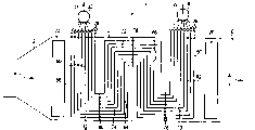
Fig. 1,2 and 3 is the steam generator vertical section of reduced representation horizontal structure respectively.
Part identical in all accompanying drawings adopts identical Reference numeral.
By Fig. 1,2 or 3 steam generator 1,1 ', 1 " form with waste heat steam generator is connected not the further exhaust gas side of the downstream from gas turbines of expression.Steam generator 1,1 ', 1 " outer wall 2 is respectively arranged, and this outer wall constitutes one can be by the blast tube 6 that flows through along the combustion gas direction x that schematically illustrates with arrow 4 of level of approximation from the used heat combustion gas of gas turbine.In this blast tube 6, be provided with some heating surfaces, also be called continuous heating surface 8,10 or 12 by continuous heating principle design.In by Fig. 1,2 and 3 embodiment, only represented a continuous heating surface 8,10 or 12 respectively, but a large amount of continuous heating surfaces also can be set.
Can be added into flow media W respectively in the carburetion system that constitutes by continuous heating surface 8,10 or 12, this flow media disposable by each continuous heating surface 8,10 or 12 o'clock vaporization, and be discharged from as steam D when continuous heating surface 8,10 or 12 is discharged, and be transfused to overheated heating surface for further overheated usually.The carburetion system that is made of each continuous heating surface 8,10 or 12 is connected in the steam turbine steam circulation of further representing among the figure.In the circulation of steam turbine steam, except that each carburetion system, also connect other heating surfaces that in Fig. 1 to 3, schematically illustrate respectively 20.Heating surface 20 can for example relate to superheater, middle pressure vaporizer, low pressure carburetor and/or preheater.
Continuously heating surface 8 is designed to be fit to supply with the lower density of mass flux of steam generator 22, and wherein steam generator 22 has a kind of natural circulation characteristic.According to this natural circulation characteristic, the steam generator 22 that comparing with another root steam generator 22 in the same continuous heating surface 8 is subjected to more adding heat has one and compares bigger flow media W flow with this another steam generator 22.In order to take simple especially structural measure to guarantee this point in reliable especially mode, heating surface 8 comprises two parts in the series connection of flow media side continuously.Wherein continuously the every steam generator 22 of heating surface 8 comprises that in first a near normal arranges the decline pipeline section 34 that can be flow through along downward direction by flow media W.Every steam generator 22 in second portion, comprise a longshore current moving medium flow to be connected decline pipeline section 34 downstreams, near normal is arranged and can be by flow media W along upward to the rising pipeline section 36 that flows through.
Rising pipeline section 36 here is connected by an overflow segment 38 with the decline pipeline section 34 of attaching troops to a unit in it.In this embodiment, overflow segment 38 is extended in blast tube 6 inside, and for spatially fixing, passes orifice plates 40 guidings that are located in the blast tube 6.Though orifice plate causes can narrowing down for the flow area part that combustion gas is used in blast tube 6; But should point out emphatically, not expression in proportion among Fig. 1 is so because the degree that orifice plate 40 narrows down the combustion gas flow area relatively is very little.
Mode as an alternative, described overflow segment also can be in the outsides of blast tube 6, guiding especially thereunder.This is especially applicable to such situation: come from the former in continuous heating surface 8 drainings of regulation of structure and work.This can realize by the drain receiver that is connected on the overflow segment during in blast tube 6 external guidance in overflow segment 38.In this case, drain receiver preferably spatially is located near the decline pipeline section, so unhinderedly keep the heating pipeline section because of the required movement of thermal expansion.
As shown in Figure 1, continuously the every steam generator 22 of heating surface 8 has a kind of shape of approximate U-shaped, and wherein, the limit of U-shaped is made of decline pipeline section 34 and rising pipeline section 36, between the connection segmental arc then constitute by overflow segment 38.In the steam generator 22 of so design, the height pressure potential of the flow media W in the zone of decline pipeline section 34 produces a kind of the promotion and flows and do not hinder mobile pressure potential with opposite in the zone of rising pipeline section 36.In other words: be in the decline pipeline section 34 the flowing of the relevant steam generator 22 of water column " propellings " of the flow media W of vaporization not, rather than hinder mobile.Thus, this steam generator 22 is seen the lower pressure loss on the whole.
In the frame mode of approximate U-shaped, every steam generator 22 in the entrance region of its decline pipeline section 34 and thereon in the outlet area of riser section 36, hangs or is fixed on covering of blast tube 6 by the version that hangs respectively.Then opposite with the lower end spatially seen of rising pipeline section 36 separately by the interconnected decline pipeline section 34 separately of its overflow segment 38, they spatially directly are not fixed in the blast tube 6.Therefore, the longitudinal dilatation of these parts of steam generator does not damage and is tolerated that jeopardously wherein, each overflow segment 38 plays the expansion arc.This layout of steam generator 22 mechanically has good especially flexibility and faces the differential expansion that occurs is insensitive aspect thermal stress.
A steam generator 22, especially thereon in the riser section 36, heated more, cause improving vaporization rate at first there, in this case, can be by for the size design of steam generator 22, make thisly to be subjected to more adding heat energy and to cause having the flow media of bigger flow to enter the steam generator 22 that this is subjected to more adding heat.
In addition, the steam generator 22 of heating surface 8 different pipe row 24 is arranged by multiple U mode nested against one another continuously.For this reason, the rising pipeline section 36 of many steam generators 22 and decline pipeline section 34 relative positioning in such a way each other in blast tube 6, that is be that a decline pipeline section 34 of seeing to be in after relatively leaning on along combustion gas direction X sets one and sees earlier rising pipeline section 36 along combustion gas direction X.By this layout a rising pipeline section 36 that is subjected to heating more consumingly is communicated with a decline pipeline section 34 that is subjected to fewer heating.By this relative positioning, also between pipeline section 24, reach a kind of self balancing effect.That is to say, in being subjected to the rising pipeline section 36 that is in the place ahead more of comparison heat intensive, be subjected to heating more the generation that can cause strong especially steam just, and thereby additional supply flow moving medium W had strong especially demand.But this just rising pipeline section 36 that is subjected to heat intensive is connected with a decline pipeline section 34 that is subjected to heating more weakly.This decline pipeline section is owing to add fewer heat among the flow media W of guiding therein, so height pressure potential that has king-sized promotion to flow, therefore, this just decline pipeline section 34 that is subjected to heating is specially adapted to the colder flow media W quantity delivered that provides additional more weakly.
Especially in this layout, a rising pipeline section 36 that is provided with distantly of a steam generator 22 is subjected to more heating, can cause in decline pipeline section 34 promoting the height pressure potential that flows to surpass and hinder mobile height pressure potential in the rising pipeline section 36 of attaching troops to a unit with it with king-sized degree, from and additionally realize to this rising pipeline section 36 supply flow moving medium W more.This outstanding especially Natural Circulation feature based on steam generator 22, make steam generator face the part and be subjected to different heating in the characteristic that a kind of self-stabilization is arranged on the king-sized degree: a row steam generator 22 is subjected to heating more and causes locally having more flow media W to infeed in these steam generator 22 row, so based on the cooling effect that correspondingly increases, the corresponding temperature value of automatic equalization.Therefore, the pipe row 24 of the steam parameter of the initial steam that flows in main gatherer 32 and each circulation are irrespectively and especially even.
According to steam generator 1,1 ', 1 " design point or the operating point of regulation, the height pressure potential that the promotion that is partly provided by the vaporization that is downward through is flowed can obviously surpass the second vaporization part that is connected the downstream and hinder the height pressure potential that flows.Therefore according to design point the first vaporization part is designed at bigger friction pressure loss.For this reason in the upstream of the steam generator 1 pipe row of pressing Fig. 1, main allocated equipment 30 and attaching troops to a unit between their each distributor 26, each connects a throttling arrangement 42, and it especially can be designed to adjustable.
Scheme as an alternative, in pressing the embodiment of Fig. 2, a continuous heating surface 10 of steam generator 1 ' comprise, its steam generator 50 equally respectively has a decline pipeline section 52 in first, be to flow through flow media W rising pipeline section 54 in parallel mutually but the longshore current moving medium flow direction connects a plurality of respectively in its downstream.By it with decline pipeline section 52 respectively with the overflow segment 56 of attaching troops to a unit and coupling together in a plurality of rising pipeline sections 54 of decline pipeline section, in the present embodiment still in blast tube 6 guided inside and be fixed in the orifice plate 58.But they also can be laid on blast tube 6 outsides when needing.In pressing the embodiment of Fig. 2, the flow direction of longshore current moving medium connects the rising pipeline section 54 of two parallel connections respectively in each decline pipeline section 52 downstream.Here the pipe of Shi Yonging has identical size, so be used for the section that flows freely of flow media W in the rising pipeline section 54 of parallel connection, is that to be connected the public decline pipeline section 52 flow section twices of their upstreams so big.Scheme as an alternative, this restriction to friction pressure loss in decline pipeline section 52 also can be by suitable size design, especially by selecting a smaller diameter to reach under the situation of needs.
" comprise a continuous heating surface 12, it is equally at smaller friction pressure loss design and thereby be specially adapted to guarantee the Natural Circulation feature under the situation of smaller density of mass flux by the steam generator in the embodiment of Fig. 31.But in addition, steam generator 1 " continuous heating surface 12 mating especially with the temperature profile that flows through the combustion gas of blast tube 6 aspect its heat absorption capacity.For this reason, each the root steam generator 60 that constitutes continuous heating surface 12 comprises that respectively a plurality of (being two in the present embodiment) longshore current moving medium flows to the decline pipeline section 62,64 and the rising pipeline section 66,68 of alternately series connection.The first decline pipeline section 62 that longshore current moving medium W flow direction is seen here is connected with the first rising pipeline section 66 that is connected its downstream by an overflow segment 70 respectively.This rising pipeline section itself is connected with the second decline pipeline section 64 that is connected its downstream by another overflow segment 72 at outlet side.This second decline pipeline section 64 is connected on the second rising pipeline section 66 by another overflow segment 74.Described three overflow segment 70,72,74 still blast tube 6 guided inside and be fixed on the bottom of blast tube 6 respectively by orifice plate 76,78 or 80 or the zone of lid in.
Claims (9)
1. steam generator (1,1 ', 1 "), wherein, can be by hot combustion gas along being provided with continuous heating surface (8 in the blast tube (6) that flows through near the combustion gas direction (X) of level, 10,12), this continuous heating surface comprises the steam generator parallel with one another (22 that some flow through for a kind of flow media (W), 50,60), and this continuous heating surface is designed to, make another steam generator (22 with same continuous heating surface, 50,60) compare a steam generator (22 that is subjected to more adding heat, 50,60) have one and this another steam generator (22,50,60) compare bigger flow media (W) flow, it is characterized by: one or every steam generator (22,50,60) comprise that respectively near normal arranges the decline pipeline section (34 that can be flow through in a downward direction by flow media (W), 52,62,64) and the flow direction of a longshore current moving medium be connected this decline pipeline section downstream, the rising pipeline section (36 that near normal is arranged and can be flow through in the upward direction by flow media (W), 54,66,68).
2. according to the described steam generator of claim 1 (1,1 ', 1 "), wherein, the decline pipeline section (34,52,62,64) of each steam generator (22,50,60) is seen along the flow direction (X) of combustion gas in blast tube (6) and is arranged on the back of the rising pipeline section of phase configuration (36,54,66,68) with it.
3. according to claim 1 or 2 described steam generators (1,1 ', 1 "), wherein, the decline pipeline section (34,52,62,64) of one or every steam generator (22,50,60) is connected with the rising pipeline section of phase configuration (36,54,66,68) with it by an overflow segment (38,70,72,74) in the flow media side.
4. according to the described steam generator of claim 3 (1,1 ', 1 "), wherein, each overflow segment (31,70,72,74) is located at blast tube (6) inside.
5. according to the described steam generator of one of claim 1 to 4 (1,1 ', 1 "), wherein, one or every steam generator (22,50,60) comprise respectively that by the design of bifurcated the flow direction of a plurality of longshore current moving mediums is connected public decline pipeline section (34,52,62, a 64) downstream for flowing through flow media (W) rising pipeline section (36,54,66,68) in parallel mutually.
6. according to the described steam generator of one of claim 1 to 5 (1,1 ', 1 "), wherein, the rising pipeline section of many steam generators (22,50,60) and decline pipeline section (36,54,66,68 and 34,52,62,64) are located in blast tube (6) by this way toward each other, that is be that a decline pipeline section of seeing to be in distant rear along combustion gas direction (X) (34,52,62,64) sets a rising pipeline section of seeing to be in distant the place ahead along combustion gas direction (X) (36,54,66,68).
7. according to the described steam generator of one of claim 1 to 6 (1,1 ', 1 "), wherein, some steam generators (22,50,60) comprise that respectively a plurality of longshore current moving mediums flow to the decline pipeline section and the rising pipeline section (36,54,66,68 and 34,52,62,64) of alternately series connection.
8. according to the described steam generator of one of claim 1 to 7 (1,1 ', 1 "), wherein, the flow direction of longshore current moving medium is in the upstream of the decline pipeline section (36,54,66,68) of one or every steam generator (22,50,60), in the tube connector of main allocated equipment, respectively be connected with a throttling arrangement (42).
9. according to the described steam generator of one of claim 1 to 8, wherein, be connected with a gas turbine in the upstream of this steam generator along the flow direction of combustion gas.
Applications Claiming Priority (2)
| Application Number | Priority Date | Filing Date | Title |
|---|---|---|---|
| DE10127830.6 | 2001-06-08 | ||
| DE10127830A DE10127830B4 (en) | 2001-06-08 | 2001-06-08 | steam generator |
Publications (2)
| Publication Number | Publication Date |
|---|---|
| CN1526059A true CN1526059A (en) | 2004-09-01 |
| CN1289853C CN1289853C (en) | 2006-12-13 |
Family
ID=7687617
Family Applications (1)
| Application Number | Title | Priority Date | Filing Date |
|---|---|---|---|
| CNB028112822A Expired - Fee Related CN1289853C (en) | 2001-06-08 | 2002-05-27 | Steam generator |
Country Status (12)
| Country | Link |
|---|---|
| US (1) | US6868807B2 (en) |
| EP (1) | EP1393001A2 (en) |
| JP (1) | JP4443216B2 (en) |
| KR (1) | KR100718357B1 (en) |
| CN (1) | CN1289853C (en) |
| CA (1) | CA2449652C (en) |
| CZ (1) | CZ20033530A3 (en) |
| DE (1) | DE10127830B4 (en) |
| PL (1) | PL199124B1 (en) |
| RU (1) | RU2004100240A (en) |
| SK (1) | SK287649B6 (en) |
| WO (1) | WO2002101292A2 (en) |
Cited By (1)
| Publication number | Priority date | Publication date | Assignee | Title |
|---|---|---|---|---|
| CN103154611A (en) * | 2010-08-04 | 2013-06-12 | 西门子公司 | Forced-flow steam generator |
Families Citing this family (22)
| Publication number | Priority date | Publication date | Assignee | Title |
|---|---|---|---|---|
| US8019633B2 (en) * | 2002-02-07 | 2011-09-13 | Micro Beef Technologies, Ltd. | Livestock management systems and methods |
| EP1443268A1 (en) * | 2003-01-31 | 2004-08-04 | Siemens Aktiengesellschaft | Steam generator |
| EP1512906A1 (en) * | 2003-09-03 | 2005-03-09 | Siemens Aktiengesellschaft | Once-through steam generator of horizontal construction and method of operating said once-through steam generator |
| EP1512905A1 (en) * | 2003-09-03 | 2005-03-09 | Siemens Aktiengesellschaft | Once-through steam generator and method of operating said once-through steam generator |
| FR2872886B1 (en) * | 2004-07-09 | 2006-09-22 | Total Sa | METHOD AND DEVICE FOR GENERATING WATER VAPOR ADAPTED TO OXY-COMBUSTION |
| US6957630B1 (en) | 2005-03-31 | 2005-10-25 | Alstom Technology Ltd | Flexible assembly of once-through evaporation for horizontal heat recovery steam generator |
| AU2006272450B2 (en) * | 2005-07-19 | 2010-09-02 | Chaozhou Three-Circle (Group) Co., Ltd. | Steam generator |
| CN101310146B (en) * | 2005-07-19 | 2010-08-18 | 塞拉米克燃料电池有限公司 | Steam generator |
| EP2255076B1 (en) | 2008-02-26 | 2015-10-07 | Alstom Technology Ltd | Method for regulating a boiler and control circuit for a boiler |
| EP2194320A1 (en) * | 2008-06-12 | 2010-06-09 | Siemens Aktiengesellschaft | Method for operating a once-through steam generator and once-through steam generator |
| PT2161525T (en) * | 2008-09-08 | 2016-07-26 | Balcke-Dürr GmbH | Modular heat exchanger |
| EP2180250A1 (en) * | 2008-09-09 | 2010-04-28 | Siemens Aktiengesellschaft | Continuous-flow steam generator |
| DE102009012320A1 (en) * | 2009-03-09 | 2010-09-16 | Siemens Aktiengesellschaft | Flow evaporator |
| DE102009012321A1 (en) * | 2009-03-09 | 2010-09-16 | Siemens Aktiengesellschaft | Flow evaporator |
| DE102009012322B4 (en) * | 2009-03-09 | 2017-05-18 | Siemens Aktiengesellschaft | Flow evaporator |
| MX362656B (en) | 2012-01-17 | 2019-01-30 | General Electric Technology Gmbh | Tube and baffle arrangement in a once-through horizontal evaporator. |
| MX358076B (en) | 2012-01-17 | 2018-08-03 | General Electric Technology Gmbh | Flow control devices and methods for a once-through horizontal evaporator. |
| DE102012218542B4 (en) * | 2012-10-11 | 2016-07-07 | Siemens Aktiengesellschaft | Method for the flexible operation of a power plant |
| EP2843304A1 (en) * | 2013-08-29 | 2015-03-04 | Casale SA | A shell-and-tube apparatus for heat recovery from a hot process stream |
| US9739476B2 (en) * | 2013-11-21 | 2017-08-22 | General Electric Technology Gmbh | Evaporator apparatus and method of operating the same |
| DE102014206043B4 (en) * | 2014-03-31 | 2021-08-12 | Mtu Friedrichshafen Gmbh | Method for operating a system for a thermodynamic cycle with a multi-flow evaporator, control device for a system, system for a thermodynamic cycle with a multi-flow evaporator, and arrangement of an internal combustion engine and a system |
| AU2019352659A1 (en) | 2018-10-01 | 2021-05-06 | Header-coil Company A/S | Heat exchanger, such as for a solar power plant |
Family Cites Families (19)
| Publication number | Priority date | Publication date | Assignee | Title |
|---|---|---|---|---|
| US589553A (en) * | 1897-09-07 | Half to francis j | ||
| DE425717C (en) | 1924-01-31 | 1926-02-24 | Hugo Dornseif | Laying nest for chickens and like |
| US2699758A (en) * | 1946-02-02 | 1955-01-18 | Svenska Maskinverken Ab | Method of preheating combustion supporting air for steam generating plants |
| DE1176155B (en) * | 1959-02-28 | 1964-08-20 | Buckau Wolf Maschf R | Steep tube boiler with an upper, cooled projection on the rear wall |
| FR2443643A1 (en) * | 1978-12-06 | 1980-07-04 | Creusot Loire | HEATING APPARATUS PROVIDING WATER VAPOR AND HOT GAS |
| US4357907A (en) * | 1980-10-27 | 1982-11-09 | Rockwell International Corporation | Fluidized bed combustor with improved indirect heat exchanger units |
| JPS61186702A (en) * | 1985-02-14 | 1986-08-20 | 三菱重工業株式会社 | Exhaust gas boiler |
| US4685426A (en) * | 1986-05-05 | 1987-08-11 | The Babcock & Wilcox Company | Modular exhaust gas steam generator with common boiler casing |
| JPH0718525B2 (en) * | 1987-05-06 | 1995-03-06 | 株式会社日立製作所 | Exhaust gas boiler |
| EP0425717B1 (en) * | 1989-10-30 | 1995-05-24 | Siemens Aktiengesellschaft | Once-through steam generator |
| JPH03221702A (en) * | 1990-01-29 | 1991-09-30 | Toshiba Corp | Duplex type heat exchanger for waste heat recovery |
| BE1005793A3 (en) * | 1992-05-08 | 1994-02-01 | Cockerill Mech Ind Sa | INDUCED CIRCULATION HEAT RECOVERY BOILER. |
| DE19651678A1 (en) * | 1996-12-12 | 1998-06-25 | Siemens Ag | Steam generator |
| DE19651936C2 (en) * | 1996-12-14 | 2000-08-31 | Nem Bv | Continuous steam generator with a throttle cable for connection to a device emitting hot gas |
| DE19700350A1 (en) * | 1997-01-08 | 1998-07-16 | Steinmueller Gmbh L & C | Continuous steam generator with gas flue and condenser heating surfaces |
| US6092490A (en) * | 1998-04-03 | 2000-07-25 | Combustion Engineering, Inc. | Heat recovery steam generator |
| US6019070A (en) * | 1998-12-03 | 2000-02-01 | Duffy; Thomas E. | Circuit assembly for once-through steam generators |
| US6588379B2 (en) * | 2001-08-06 | 2003-07-08 | Bwx Technologies, Inc. | Multi-stream energy source steam generator system |
| US6557500B1 (en) * | 2001-12-05 | 2003-05-06 | Nooter/Eriksen, Inc. | Evaporator and evaporative process for generating saturated steam |
-
2001
- 2001-06-08 DE DE10127830A patent/DE10127830B4/en not_active Expired - Fee Related
-
2002
- 2002-05-27 JP JP2003504017A patent/JP4443216B2/en not_active Expired - Fee Related
- 2002-05-27 RU RU2004100240/06A patent/RU2004100240A/en not_active Application Discontinuation
- 2002-05-27 KR KR1020037016063A patent/KR100718357B1/en not_active IP Right Cessation
- 2002-05-27 CN CNB028112822A patent/CN1289853C/en not_active Expired - Fee Related
- 2002-05-27 CA CA002449652A patent/CA2449652C/en not_active Expired - Fee Related
- 2002-05-27 PL PL367197A patent/PL199124B1/en not_active IP Right Cessation
- 2002-05-27 CZ CZ20033530A patent/CZ20033530A3/en unknown
- 2002-05-27 EP EP02729915A patent/EP1393001A2/en not_active Withdrawn
- 2002-05-27 US US10/479,994 patent/US6868807B2/en not_active Expired - Fee Related
- 2002-05-27 WO PCT/DE2002/001936 patent/WO2002101292A2/en active Application Filing
- 2002-05-27 SK SK1606-2003A patent/SK287649B6/en not_active IP Right Cessation
Cited By (3)
| Publication number | Priority date | Publication date | Assignee | Title |
|---|---|---|---|---|
| CN103154611A (en) * | 2010-08-04 | 2013-06-12 | 西门子公司 | Forced-flow steam generator |
| CN103154611B (en) * | 2010-08-04 | 2016-03-16 | 西门子公司 | Forced once-through boiler |
| US9291344B2 (en) | 2010-08-04 | 2016-03-22 | Siemens Aktiengesellschaft | Forced-flow steam generator |
Also Published As
| Publication number | Publication date |
|---|---|
| KR100718357B1 (en) | 2007-05-14 |
| DE10127830B4 (en) | 2007-01-11 |
| WO2002101292A3 (en) | 2003-10-02 |
| PL199124B1 (en) | 2008-08-29 |
| CN1289853C (en) | 2006-12-13 |
| US20040149239A1 (en) | 2004-08-05 |
| RU2004100240A (en) | 2005-05-27 |
| WO2002101292A2 (en) | 2002-12-19 |
| JP4443216B2 (en) | 2010-03-31 |
| SK287649B6 (en) | 2011-05-06 |
| PL367197A1 (en) | 2005-02-21 |
| KR20040011530A (en) | 2004-02-05 |
| US6868807B2 (en) | 2005-03-22 |
| SK16062003A3 (en) | 2005-02-04 |
| CA2449652A1 (en) | 2002-12-19 |
| DE10127830A1 (en) | 2002-12-12 |
| CA2449652C (en) | 2007-12-11 |
| JP2004529310A (en) | 2004-09-24 |
| CZ20033530A3 (en) | 2004-04-14 |
| EP1393001A2 (en) | 2004-03-03 |
Similar Documents
| Publication | Publication Date | Title |
|---|---|---|
| CN1289853C (en) | Steam generator | |
| CN101684937B (en) | Steam generator | |
| CN1856680B (en) | Method for starting a continuous steam generator and continuous steam generator for carrying out said method | |
| KR100439080B1 (en) | Waste heat steam generator | |
| US6334410B2 (en) | Exhaust heat recovery boiler | |
| CN1289854C (en) | Method for starting steam generator with laterally arranged fire gases traversing channel and the steam generator thereof | |
| CN1126905C (en) | Continuous-flow steam generator and method for starting same | |
| CN102575839A (en) | Continuous evaporator | |
| CN1103424C (en) | Continuous vertical-to-angular tube transitions | |
| CN102089583B (en) | Continuous steam generator | |
| CN102483228B (en) | Continuous evaporator | |
| CN100420900C (en) | Continuous steam generator and method for operating said continuous steam generator | |
| CN105992912A (en) | Combined cycle power plant | |
| RU2351844C2 (en) | Uniflow steam generator of horizontal design type and method of uniflow steam generator operation | |
| US7116899B2 (en) | Operating method for a horizontal steam generator and a steam generator for carrying out said method | |
| KR101619561B1 (en) | Continuous steam generator | |
| KR101662348B1 (en) | Continuous evaporator | |
| CN1016887B (en) | Upflow / downflow heated tube circulating system | |
| CN1732357A (en) | Method of manufacturing a once-through steam generator and the once-through steam generator |
Legal Events
| Date | Code | Title | Description |
|---|---|---|---|
| C06 | Publication | ||
| PB01 | Publication | ||
| C10 | Entry into substantive examination | ||
| SE01 | Entry into force of request for substantive examination | ||
| C14 | Grant of patent or utility model | ||
| GR01 | Patent grant | ||
| C17 | Cessation of patent right | ||
| CF01 | Termination of patent right due to non-payment of annual fee |
Granted publication date: 20061213 Termination date: 20130527 |