CN1498514A - System and methods for sensing acoustic signal using micro-electronical system technology - Google Patents
System and methods for sensing acoustic signal using micro-electronical system technology Download PDFInfo
- Publication number
- CN1498514A CN1498514A CNA028067878A CN02806787A CN1498514A CN 1498514 A CN1498514 A CN 1498514A CN A028067878 A CNA028067878 A CN A028067878A CN 02806787 A CN02806787 A CN 02806787A CN 1498514 A CN1498514 A CN 1498514A
- Authority
- CN
- China
- Prior art keywords
- microphone
- vibrating membrane
- sound
- material layer
- elongated member
- Prior art date
- Legal status (The legal status is an assumption and is not a legal conclusion. Google has not performed a legal analysis and makes no representation as to the accuracy of the status listed.)
- Pending
Links
Images


Classifications
-
- H—ELECTRICITY
- H04—ELECTRIC COMMUNICATION TECHNIQUE
- H04R—LOUDSPEAKERS, MICROPHONES, GRAMOPHONE PICK-UPS OR LIKE ACOUSTIC ELECTROMECHANICAL TRANSDUCERS; DEAF-AID SETS; PUBLIC ADDRESS SYSTEMS
- H04R23/00—Transducers other than those covered by groups H04R9/00 - H04R21/00
Landscapes
- Physics & Mathematics (AREA)
- Engineering & Computer Science (AREA)
- Acoustics & Sound (AREA)
- Signal Processing (AREA)
- Pressure Sensors (AREA)
- Measurement Of Velocity Or Position Using Acoustic Or Ultrasonic Waves (AREA)
- Electrostatic, Electromagnetic, Magneto- Strictive, And Variable-Resistance Transducers (AREA)
- Details Of Audible-Bandwidth Transducers (AREA)
- Soundproofing, Sound Blocking, And Sound Damping (AREA)
Abstract
An acoustic system has an acoustic sensor and a processing circuit. The acoustic sensor includes a base, a microphone having a microphone diaphragm supported by the base, and a hot-wire anemometer having a set of hot-wire extending members supported by the base. The set of hot-wire extending members defines a plane which is substantially parallel to the microphone diaphragm. The processing circuit receives a sound and wind pressure signal from the microphone and a wind velocity signal from the hot-wire anemometer, and provides an output signal based on the sound and wind pressure signal from the microphone and the wind velocity signal from the hot-wire anemometer (e.g., accurate sound with wind noise removed). The configuration of the hot-wire extending members defining a plane which is substantially parallel to the microphone diaphragm can be easily implemented in a MEMS device making the configuration suitable for miniaturized applications.
Description
Technical field
The present invention relates to system and method with the micro-electronic mechanical system technique acoustic signals.
Background technology
Microphone is the transducer that air pressure sampling (being acoustical signal) is converted to the signal of telecommunication.In typical power microphone, the relative magnetic field of the vibrating membrane of microphone moving coil makes electric current flow into coil.In typical Electret Condencer Microphone, the vibrating membrane of microphone (as charged metal electrode board, electret etc.) moves with respect to rigid back, and electric current is flowed out from power supply, produces constant potential difference between microphone vibrating membrane and rigid back.
Wind noise can disturb the ability of microphone senses voice signal.Such as, when a people aimed at microphone talk, wind noise can be covered this people's sound, the sound ambiguous that causes the device (as loudspeaker, phonographic recorder, transmitter, loud speaker etc.) that links to each other with microphone to spread out of.Wind noise can also be covered important acoustic information, makes such as automatic target/object recognition device, and the decreased performance of automatic systems such as system such as is distinguished in the orientation.
Some microphone arrangement windscreen, cover on the microphone, be intended to reduce by microphone senses to wind noise.Conventional windscreen is common in and covers above the microphone that the televised report hands, and it is to be made by sponge, and spherical in shape (as cover on the microphone, diameter is about 10 centimetres sponge ball).This windscreen is used for many years, and effectively removal can make the crucial delphic wind noise of sound (as televised report's sound) (as tedious rumble).
The mode removed with electricity is attempted in some scientific experiments, removes wind noise (such as obtaining acoustical signal from passing truck) from the sound of target location and wind noise.Usually, these tests utilize microphone sensing sound and blast, (such as several millimeters places of distance microphone) are provided with a cover hot wire anemometer around microphone, in order to senses wind speed, and with computer device stores and handle by microphone senses to sound and blast, simultaneously, by the measured wind speed of hot wire anemometer.Typical hot wire anemometer is a kind of device of fragility, and it is measured because the thermal loss (loss of heat or energy is directly related with wind speed) that circuit causes is crossed in wind by a bit of circuit of heating (such as one section 1.5mm long tungsten or platinum).
A kind of method that realizes above-mentioned test will be described below.First mould-number (A/D) transducer will become digitized sound and wind pressure signal from the conversion of signals of microphone, and these signals are stored in the memory of computer.Simultaneously, second A/D converter will become digitized thermal loss signal from the conversion of signals of hot wire anemometer, and these signals also are stored in the memory.Next, digital signal processor processes sound and wind pressure signal and thermal loss signal.Particularly, adopt a kind of algorithm, can utilize the thermal loss signal to produce wind pressure data, and from sound and wind signal, deduct wind pressure data.Although experimental result is still mixed signal, notional result should be to obtain a voice signal of having removed wind noise from the target location.
The full content of the following two pieces of articles of above-mentioned laboratory reference, one piece is at the Acoustical Society in October, 1998 of America 136
ThAmong the Meeting Lay Language Paper, by the article that is called " Electronic Removal of Outdoor Microphone Windownoise " of people such as Shust work.Another piece is interim at AIAA periodical the 35th volume the 1st in January, 1997, by the article that is entitled as " Low Flow-noise Microphone for Active NoiseControl Applications " of people such as McGuinn work.These experiments provide stem-winding result of the test, but that prerequisite is the air-flow that is sent on the microphone vibrating membrane is fully normal.Experiment and wind signal algorithm (as hydrodynamic equations) that another of this paper reference is relevant are described in the paper of being shown by Shust in the Michigan engineering college electro-engineering thesis for the doctorate on March 6th, 1998 (Ph.D.Dissertation in Electrical Engineering) that is entitled as " Active Removal of wind Noise from Outdoor Microphoneusing Local Velocity Measurements " to some extent.
Summary of the invention
Regrettably, traditional minimizing microphone senses has the some shortcomings part to the method for wind noise.For example, above-mentioned traditional windscreen is bulky, has therefore influenced the application (as the application at aspects such as hearing aids, hands-free phone equipment, hiding surveillance equipments) of some specific microphones.In addition, this windscreen bulky is an impediment to the trend (as palm video camera, mobile phone etc.) of current microphone and audio system miniaturization.In addition, want to keep windscreen to remove the effect of wind noise, windscreen just can't be realized miniaturization.
As for another conventional method mentioned above, be that a cover hot wire anemometer is set around microphone, remove the sound of microphone institute sensing and the wind noise in the wind pressure signal in the mode of electricity, this method produces the effect of mixing, but also can not remove wind noise as windscreen effectively.The effect of this mixing is owing to multiple factor.Such as, hot wire anemometer can not sensing from the wind noise of microphone present position, but the wind noise of sensing microphone adjacent locations (being several millimeters places of distance microphone), and this wind noise is compared with the wind noise of microphone present position and is had marked difference.And when blowing to the wind process microphone of anemometer, the air-flow around the microphone changes the wind speed at anemometer place, thereby makes system introduce error.In addition, this method only fully just often is only effectively at the wind that blows on the microphone vibrating membrane.
In addition, above-mentioned traditional mode with electricity method of removing wind noise also has the defective that some are implemented.Need a large amount of computer equipment (such as the memory of a plurality of A/D converters, storage signal information, use the technology etc. of sound and wind pressure signal and wind velocity signal being carried out Digital Signal Processing) such as, some method.In addition, these methods are after signal message is digitized and is saved to memory, deduct wind pressure data from sound and wind signal, and this just need use memory, and need the time of wait.Such postpone processing method is not suitable for some special applications, and (in real time promptly) removes the audio system of wind noise in using such as needs, for example, and Live Audio, mobile phone, military/national defence battlefield transducer, hearing aids etc.
Compare with the method for above-mentioned traditional minimizing wind noise, several specific embodiments of the present invention all provide a kind of use microelectromechanical systems (MEMS) technology directly the method for voice signal.For example, the sensing part as microphone and hot wire anemometer can be arranged in (as on a position, being provided with or being in contact with one another) in the MEMS device with minimum interval.Therefore, basically can be at same position senses wind speed, sound and blast.So, generate an accurate wind pressure signal according to wind speed, then, from sound and wind pressure signal, deduct the wind pressure signal that is generated again, so just provide an accurate voice signal of removing wind noise.
According to a kind of scheme of the present invention, an audio system is provided, described audio system comprises sound transducer and treatment circuit.Described sound transducer comprises (i) pedestal, (ii) is supported on the microphone on the described pedestal, and this microphone has a microphone vibrating membrane and (iii) places hot wire anemometer on the described pedestal, and this hot-wire array is in respect of one group of hot line elongated member.A plane of this group hot line elongated member is parallel fully with the microphone vibrating membrane.
Described treatment circuit receives sound and wind pressure signal from microphone, receive wind velocity signal from hot wire anemometer, and provide an output signal (such as the accurate voice signal of removal wind noise) with the wind velocity signal that receives from hot wire anemometer according to sound that receives from microphone and wind pressure signal.Because a plane of hot line elongated member is parallel fully with the microphone vibrating membrane, so hot line elongated member and microphone vibrating membrane can lean on each other very nearly (such as separating small, limited distance), perhaps even contact with each other, so just can sense accurate wind speed, sound and the blast of same position.
According to a kind of scheme, the ground floor electric conducting material is microphone vibrating membrane (such as polysilicon, a silicide etc.), and second layer electric conducting material is this group hot line elongated member (such as tungsten).According to this scheme, described pedestal comprises substrate (such as silicon), is used for supporting described ground floor and second layer electric conducting material.Therefore, can be used as the MEMS device and realize described sound transducer.Because this MEMS sound transducer can provide the sound of removing wind noise, so this MEMS sound transducer can be called MEMS electronics windscreen microphone (MEWM).
According to a kind of scheme, described acoustic sensor microphone also comprises a rigid element (as a backboard), and it is parallel fully with the microphone vibrating membrane, forms the cavity of Electret Condencer Microphone.According to this scheme, the 3rd layer of electric conducting material is the rigid element of microphone.Described the 3rd layer of electric conducting material of described substrate supports.Preferably make described microphone vibrating membrane extend to described pedestal always, between hot line elongated member and Electret Condencer Microphone cavity, form sealing.This is arranged, then the microphone vibrating membrane can stop contaminant (as dust, moisture, particle, fragment etc.) along as described in the hot line elongated member enter the cavity of Electret Condencer Microphone.The cavity that contaminant enters Electret Condencer Microphone will cause the microphone operation failure.
According to a kind of scheme, described this group hot line elongated member comprises a plurality of tungsten filament electric bridges, and these electric bridges are parallel fully in the plane that the hot line elongated member limits.Therefore,, can heat the tungsten filament electric bridge, and measure wind and cross the thermal loss that electric bridge causes in order to obtain to convert to the thermal loss value of wind speed.
According to a kind of scheme, described sound transducer also comprises the protective material (as silicon nitride) of one deck by substrate supports.Preferably this layer protective material made latticed, thereby, make sound wave energy arrive this group hot line elongated member and microphone vibrating membrane by protective material from the outside.Correspondingly, this grid can make sound and wind enter anemometer and microphone from the outside, has yet reduced the possibility that dirt enters anemometer and microphone.
According to a kind of scheme, described ground floor electric conducting material is determined a plurality of microphone vibrating membranes.Preferably make a plurality of microphone vibrating membranes be arranged in the microphone vibrating membrane array (N and M are positive integers) of two-dimentional N * M.In addition, described second layer electric conducting material is determined many group hot line elongated members.Preferably make many group hot line elongated members be arranged in the array of the hot line elongated member group of two-dimentional N * M, and corresponding with the microphone vibrating membrane array of described two-dimentional N * M.Thus, described sound transducer has a plurality of sensing parts (a pair of microphone and anemometer), in order to increase stability, for example, strengthens fault-tolerant ability, improves signal to noise ratio (promptly reducing random noise in some special sensing parts) etc.
According to a kind of scheme, the microphone vibrating membrane array of described two-dimentional N * M comprises: the first row microphone vibrating membrane, in order to the sound wave in the response first frequency scope (as 0-10KHz); Also comprise the second row microphone vibrating membrane, in order to the sound wave in the response second frequency scope; Described second frequency scope different with the first frequency scope (such as being 10-20KHz).Other each row can respond other frequency range.So this sound transducer can be specially adapted for the sound (such as voice, vehicle signal etc.) of sensing specific type.
According to a kind of scheme, described treatment circuit comprises a switching stage, be used for converting the wind velocity signal that hot wire anemometer records to contain the blast component simulated wind pressure signal, also comprise an output stage, be used for the blast component that deducts the simulated wind pressure signal from the sound and the wind pressure signal of microphone, thereby generate output signal.Removed the voice signal of wind noise for output in real time, described scheme can be operated in real time.Therefore, this scheme is applicable to the occasion that need remove wind noise then and there, as the battlefield transducer of Live Audio, mobile phone, military/national defence, hearing aids etc.
According to a kind of scheme, described switching stage and output stage are provided in a side of the analog circuit in the application-specific integrated circuit (ASIC) (ASIC).So just can in very little space, encapsulate whole system (as the MEMS device of sound transducer and the ASIC device of treatment circuit).
According to a kind of scheme, described treatment circuit comprises a correlation level, is used to make the wind velocity signal digitlization, and a series of wind pressure values in digitized wind velocity signal and the check table are connected, and provides a series of wind pressure value with the form of coherent signal.The treatment circuit here also comprises an output stage, is used for (i) and receives coherent signal from correlation level, (ii) receives sound and wind signal from microphone, (iii) deducts this string wind pressure value from sound and wind pressure signal, generates output signal then.This scheme is used a kind of algorithm to wind velocity signal.According to this scheme, described system does not need switching stage, perhaps can walk around switching stage.
As mentioned above, characteristics of the present invention can be used for audio system, audio unit and acoustic method and other electronic equipments, for example, some equipment of the Textron Systems company of Massachusetts Wilmington.
Description of drawings
In the preferred embodiment of the present invention below, will describe above-mentioned and other purposes, characteristics and advantage of the present invention with reference to the accompanying drawings in detail; The same section of describing in institute's drawings attached all adopts identical Reference numeral.
Fig. 1 is the block diagram that is applicable to audio system of the present invention;
Fig. 2 is the perspective view of sound transducer each several part in the audio system of Fig. 1;
Fig. 3 is the side cutaway view when sound transducer among Fig. 1 is used as microelectromechanical systems (MEMS) device;
Fig. 4 is the vertical view of sound transducer in the accompanying drawing 3;
Fig. 5 is the vertical view of the used hot line parts of the hot wire anemometer of sound transducer in Fig. 3 and 4;
Fig. 6 is to use the program flow diagram of the audio system of Fig. 1;
Fig. 7 is the vertical view with sound transducer of sound sensing part array;
Fig. 8 is can be for the block diagram of the audio system that selects, and this audio system has a plurality of levels, generates wind pressure signal in order to the measured value according to wind speed;
Fig. 9 is the profile of a MEMS structure, and described structure comprises substrate, epitaxial loayer, layer of conductive material and photoresist zone (behind Butut after use photoetching and the photomask technology);
Figure 10 is the profile after the MEMS structure among Fig. 9 is removed partially conductive material layer and photoresist zone;
Figure 11 is the profile after the MEMS structure among Figure 10 has been added low temperature oxide layer and photoresist zone;
Figure 12 is the profile after the MEMS structure among Figure 11 has been removed low-temperature oxidation layer segment and photoresist zone;
Figure 13 is that the MEMS structure among Figure 12 has been added polyimides and made the polished profile afterwards of body structure surface;
Figure 14 is the profile after the MEMS structure among Figure 13 has been added layer of conductive material (as tungsten);
Figure 15 is the profile after the MEMS structure among Figure 14 has been added the photoresist zone;
Figure 16 is the profile after the MEMS structure among Figure 15 has been removed conductive material layer and photoresist zone;
Figure 17 is that the MEMS structure among Figure 16 has been added the profile behind the polyimides;
Figure 18 is that MEMS structure among Figure 17 is by attached profile behind the photoresist zone;
Figure 19 is the profile after the MEMS structure among Figure 18 has been removed part polyimides and photoresist zone;
Figure 20 is the profile after the MEMS structure among Figure 19 has been added one deck base material (as the nitride of plasma-reinforced chemical vapor deposition) and photoresist zone;
Figure 21 is the profile after the MEMS structure among Figure 20 has been removed base material part and photoresist;
Figure 22 is the profile after the MEMS structure among Figure 21 has been added the layer protective layer material;
Figure 23 is that the MEMS structure among Figure 22 goes up by the profile after having added the photoresist zone at substrate (being the bottom of MEMS device);
Figure 24 is the profile after the MEMS structure among Figure 23 has been removed substrate part (as anisotropic wet etching);
Figure 25 is that the MEMS structure among Figure 24 is removed profile after the photoresist part from substrate;
Figure 26 is the lateral sectional view of another kind of MEMS structure, and this MEMS structure comprises substrate, Pyrex layer, epitaxial loayer, conductive material layer and photoresist zone;
Figure 27 is the profile after the MEMS structure among Figure 26 has been removed electric conducting material layer segment and photoresist zone;
Figure 28 is the profile after the MEMS structure among Figure 27 has been added the photoresist zone;
Figure 29 is the profile after the MEMS structure among Figure 28 has been removed epitaxial loayer and photoresist area part;
Figure 30 is the profile of the MEMS structure among Figure 29, after being reversed, described MEMS structure added one deck protective material layer on the epitaxial loayer of this structure residual and the conductive material layer, and after Pyrex layer segment and substrate have partly covered the photoresist zone, through anisotropic etching, to form the cavity part of Electret Condencer Microphone;
Figure 31 is a kind of profile of MEMS device, and this MEMS device is the MEMS structure of the MEMS structure of Figure 25 and Figure 30 to be bonded together (as through anodic bonding), and removes and form behind the protective layer, has the MEMS device of a plurality of sound transducers in order to formation;
Figure 32 is the flow chart that is applicable to the MEMS device forming process of audio system among Fig. 1;
Figure 33 is the side cut away view of another kind of MEMS structure, and this structure comprises substrate and photoresist zone;
Figure 34 is the side cutaway view of the MEMS structure among Figure 33, and this structure has been removed part substrate and photoresist zone, forms a plurality of holes, as selecting, is to have drilled through a plurality of holes on solid substrate perhaps;
Figure 35 is the side cutaway view of the MEMS structure among Figure 34, and this structure has covered layer of conductive material on substrate, and making the hole in the described substrate is (such as the electron beam evaporation layer of conductive material on substrate) of opening wide;
Figure 36 is the side cutaway view after the MEMS structure among Figure 35 has been added the photoresist zone;
Figure 37 is the side cutaway view after the MEMS structure among Figure 36 has been removed electric conducting material part and photoresist zone;
Figure 38 is a kind of profile of MEMS device, and this MEMS is bonded together (as through anodic bonding) with MEMS structure among Figure 25 and the MEMS structure among Figure 37, and removes and to form behind the protective layer, has the MEMS device of a plurality of sound transducers with formation;
Figure 39 is the profile after the MEMS structure among Figure 23 has been removed part substrate (as the anisotropic plasma etching).
Embodiment
Various embodiments of the present invention all relate to the method for utilizing microelectromechanical systems (MEMS) technology to obtain voice signal.For example, the sensing part such as microphone and hot wire anemometer can be arranged in the MEMS device (such as, can separately be disposed in a position by limited precision).Therefore, can be at almost same position place measuring wind, sound and blast.As a result, generate wind pressure signal, from the sound of this position and wind pressure signal, deduct the wind pressure signal that is generated then, thereby the accurate voice signal of having removed wind noise is provided according to the wind speed of this position.
Fig. 1 is applicable to that a sound of the present invention passes the block diagram of system 40.Described sound passes system 40 and comprises sound transducer 42 and treatment circuit 44.Described sound passes system 40 and also comprises adjunct circuit 46 (routine register, amplifier, transmitter etc.).Described sound transducer 42 comprises hot wire anemometer 48 that is used for senses wind speed and the microphone 50 that is used for sensing sound and blast.Described treatment circuit 44 comprises switching stage 52, is used for converting wind speed information to blast information, also comprises output stage 54, is used to export the acoustic information of having removed wind noise.Described audio system 40 can effectively be removed on-fixed and the nonlinear wind noise that enters microphone 50, and does not need traditional foamed windscreen.Only as example, described adjunct circuit 46 comprises mould-number (A/D) transducer 56 and digital signal processor 58, is used to handle the acoustic information from output stage 54 outputs.
Preferably described sound transducer 42 is made a MEMS device (being micro mechanical device).Like this, described sound transducer 42 just is applicable to the situation of miniaturization, as palm video camera, mobile phone, hidden surveillance equipment etc.The situation (as handheld microphone) that also can be used for non-miniaturization.Because sound transducer 42 can provide the acoustic information of having removed wind noise, so the MEMS device of sound transducer 42 can be called easily MEMS electronics windscreen microphone (MEWM).
In addition, described treatment circuit 44 can be encapsulated in the single integrated circuit (IC), for example application-specific integrated circuit (ASIC) (ASIC).According to a kind of scheme, described treatment circuit 44 is proprietary analog circuits in the ASIC, so just reduced demand to a plurality of A/D converters, just described adjunct circuit 46 has only an A/D converter to make the information digitalization of audio system 40, rather than in above-mentioned scientific experiment in the past, need a plurality of transducers to change wind velocity signal, sound and wind pressure signal respectively.A plurality of sound transducers 42 can be realized as a MEMS device, and analog circuit can be removed the wind noise in the sound/sound of output stage 54 output.According to another kind of scheme, described processing unit 44 can be can be used as hybrid circuit and realize, just a plurality of IC package blocks are assembled on the minitype circuit board.
In the course of work of audio system 40, in order to obtain not have clearly the voice signal of wind noise, described audio system 40 changes into the equivalent electric signal of sound with original physics wind velocity signal (being wind/turbulent air jet/rate signal), and deducts this signal of telecommunication from the whole microphone signals that comprise sound and blast part.Particularly, hot wire anemometer 48 provides a wind velocity signal 60 (being the thermal loss signal) for switching stage 52.Switching stage 52 converts wind velocity signal 60 to wind pressure signal 62, and this wind pressure signal 62 is transported to described output stage 54.This output stage 54 receives described wind pressure signal 62 from switching stage 52, simultaneously, also receives sound and wind pressure signal 64 from microphone 50, and to output signal 66 of described additional treatments circuit 46 outputs.Described output signal 66 is according to generating from the wind pressure signal 62 of switching stage 52 with from the sound and the wind pressure signal 64 of microphone 50.Especially, described output signal 66 comprises the sound of having removed wind noise by microphone 50 sensings.According to a kind of scheme, described output signal 66 is analog signals, can convert thereof into digital signal 68 by A/D converter 56, in order that utilize digital signal processor 58 that it is carried out signal processing.
Should be appreciated that, because the conversion between wind velocity signal 60 and the wind pressure signal 62 has caused the delay between sound and wind pressure signal 64 and the wind pressure signal 62, can be by in sound and wind pressure signal 64, introducing a this delay of little delay compensation.Can wait and realize this little delay by using long conductor (as than the pathways of conductive material of length, long etching line etc.), delay buffer.Below with reference to Fig. 2 to further specifying the present invention.
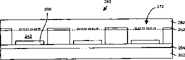
The perspective view of the assembly 70 of sound transducer 42 in Fig. 2 presentation graphs 1.Assembly 70 comprises microphone vibrating membrane 72 and the rigid element 74 (being rigid back) that constitutes microphone 50 (being Electret Condencer Microphone).Determine hole 76 on the described rigid element 74.Assembly 70 also comprises a group of hot line elongated member 78-A, 78-B of hot wire anemometer 48 ... (forming described elongated member 78 jointly).This group hot line elongated member 78 is strictly parallel with microphone vibrating membrane 72.Assembly 70 also comprises the latticed protective material layer 80 of one deck (as crisscross grid).Sound and wind 86 can activate microphone 50 by the gap between the hole 84 in the grid of hot line elongated member 78 and protective material 80 82.Hereinafter will further specify the present invention with reference to figure 3 and 4.
What Fig. 3 and 4 provided the side cutaway view 90 of sound transducer 42 among Fig. 1 and Fig. 3 midplane 106 respectively overlooks Figure 110 (being the plane 106 of microphone vibrating membrane 72).Shown in Fig. 3 and 4, sound transducer 42 comprises pedestal 94, and it is in order to support microphone vibrating membrane 72 and rigid element 74 (also visible Fig. 2).According to a kind of scheme, described sound transducer 42 is the MEMS device, and pedestal 94 forms (as silicon, epitaxial silicon, low temperature silicon dioxide, plasma nitride etc.) by multilayer material.Pedestal 94 also supports the grid (not shown among Fig. 4) of hot line elongated member 78 (shown in the dotted line among Fig. 4) and protective material 80.
Pedestal 94 forms the cavity 96 of Electret Condencer Microphone between microphone vibrating membrane 72 and rigid element 74, and the sound transducer opening 98 that leads to external position 100.By the gap 82 between the hole 84 in hot line elongated member 78 and protective material 80 grids, sound 102 and wind 104 can pass to microphone vibrating membrane 72 from external position 100.Hole 76 in the rigid element 74 makes air can pass in and out the cavity of described Electret Condencer Microphone, and this just makes microphone vibrating membrane 74 when response sound 102 and wind 104, is easy to 74 vibrations of relative stiffness parts.
Should be understood that, because microphone vibrating membrane 72 has well sealed the cavity 96 of Electret Condencer Microphone, enter the cavity 96 of Electret Condencer Microphone from position 100 so can prevent pollutant (as dust, moisture, powder etc.).In addition, the device package of sound transducer 42 also can stop pollutant to pass through the cavity 96 that hole 76 (being air vent hole) enters Electret Condencer Microphone.
Be understood that the plane 106 of described one group of hot line elongated member 78 is strict parallel with microphone vibrating membrane 72.In addition, will also be understood that, preferably micro mechanical device is realized described sound transducer 42, thereby these group hot line parts 78 are disposed at basically with microphone vibrating membrane 72, that is to say, minimum interval (such as several microns) is arranged between hot line elongated member 78 and the microphone vibrating membrane 72, perhaps also can contact with each other as selecting.Therefore, hot wire anemometer 48 and microphone 50 can be at same position difference senses wind speed, sound and blast.In addition, because this configuration, the sound of 42 pairs of all directions of sound transducer and air-flow all are effectively, and it is fully normal to require to flow to the sound and the air-flow of microphone vibrating membrane not needing in some scientific experiment.Further specify the present invention below with reference to Fig. 5.
Fig. 5 is the vertical view of hot line parts 120 in the hot wire anemometer 48.Described hot line parts 120 comprise one group of hot line elongated member 78 (also can referring to Fig. 2 and 4), one a group of link 122 and an assembly welding dish 124.Link 122-A is connected to pad 124-A with the afterbody of each hot line elongated member 78, and another link 122-B is connected to another pad 124-B with another afterbody of each hot line elongated member 78.As mentioned above, this group hot line elongated member 78 is supported by pedestal 94, thus each elongated member 78 just form one with the parallel planes 106 (referring to Fig. 3) of microphone vibrating membrane 72 strictnesses.
Duration of work is because flowing through of electric current raises this group hot line elongated member 78 (as tungsten) temperature.Wind is through each hot line elongated member 78 and take away heat, thereby the curtage that causes flowing through each hot line elongated member 78 changes, and this variation can detect by processed circuit 44.Therefore, hot line elongated member 78 can be indicated wind speed accurately, and this wind speed can convert wind pressure signal to.Further specify the present invention below with reference to Fig. 6.
In step 134, sound and blast on the microphone 50 response microphones vibrating membranes 72 in the sound transducer 42 generate sound and wind pressure signal 64 (can referring to Fig. 1).According to a kind of scheme, described microphone 50 generates a current signal, as described sound and wind pressure signal 64.And press another program, described microphone 50 generates a voltage signal, as described sound and wind pressure signal 64.
In step 136, the wind speed on the described one group of hot line elongated member 78 of hot wire anemometer 48 responses in the sound transducer 42 generates wind velocity signal 60.According to a kind of scheme, this group hot line elongated member 78 comprises one group of tungsten filament electric bridge, in order to a current signal to be provided, as described wind velocity signal 60 (being the thermal loss signal).And press another program, described anemometer 48 provides a voltage signal, as described wind velocity signal 60.It is more desirable carrying out step 134 and 136 simultaneously, so sound and wind pressure signal 64 and/or wind velocity signal 62 can not delayed time, perhaps only minimum time-delay (for example using one or more prolonging to make buffer) need be arranged.
In step 138, treatment circuit 44 is according to described sound and wind pressure signal 64 and wind velocity signal 60 generation output signals 66.Switching stage 52 in the particularly described treatment circuit 44, it converts wind velocity signal 60 to a simulated wind pressure signal 62 (being the blast current signal) that contains the blast component.Then, described output stage 54 generates output signal 66 according to from the sound of microphone 50 and wind pressure signal 64 with from the simulated wind pressure signal 62 of described switching stage 52.Such as, output stage 54 deducts the blast component in the simulated wind pressure signal 62 from sound and wind pressure signal 64.Described output signal 66 voice signal behind the wind noise that has been the microphone senses removals of arriving.Described output signal 66 also can be subjected to the processing (as filtering, amplification, digitlization, store, duplicate, transmission etc.) of adjunct circuit 46.Further specify the present invention below with reference to Fig. 7.
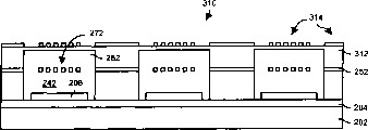
Be understood that the above-mentioned sound transducer 42 that comprises a hot wire anemometer 48 and a microphone 50 only is an example.In other scheme, described sound transducer 42 comprises many to anemometer and microphone.Fig. 7 represents to have the vertical view of the sound transducer 140 of a plurality of sound sensing parts 142.Each sound sensing part 142 comprises together a hot wire anemometer 48 and the microphone 50 (being a pair of anemometer/microphone) of being configured in shown in Fig. 3 and 4.That is to say that the hot wire anemometer 48 and the microphone 50 of each sensing component are integrated in together.According to a kind of scheme, with described each hot line elongated member 78 be arranged on microphone vibrating membrane 72 directly over (such as the slight gap of having only several microns).Press another program, described each hot line elongated member 78 is arranged on the top (promptly being in contact with one another) of microphone vibrator 72.These two kinds of schemes are measuring wind accurately, all is better than the test of traditional one or several hot wire anemometer of usefulness, and the hot wire anemometer distance microphone has several millimeters (even farther distances) in the traditional experiment.
In sound transducer 140, described each sound sensing part 142 is aligned to the array (only be example, N and M equal 3 among Fig. 7) of N * M.Therefore, sound transducer 140 is a miniature sound transducer array basically.
If sound transducer 140 is made a micro mechanical device, this sound transducer 140 preferably includes conductor path 144-1,144-2... (constituting conductor 144 jointly), and these conductor paths will be crossed each hot wire anemometer 48 of sound sensing part 142 and microphone 50 systematically and be connected to treatment circuit 44 (can referring to Fig. 1).Look back Fig. 4, it illustrates the conductor path 112 of the weak point of a connection microphone vibrating membrane 72 and pad 114.The outer lead (not shown) preferably similarly but long conductor path 144, extends to the pad locations of external array 140, so can be realized being electrically connected between sound transducer array 140 and the treatment circuit 44 from each sound sensing part 142.Only be example, Fig. 7 illustrates the conductor 144 that respectively connects sound sensing part 142 with the form of row.
According to a kind of scheme, each sound sensing part 142 is adjusted to different particular frequency range.For example, the first sound sensing part 142 of sound transducer 140 is adjusted to the first frequency scope of 0-10KHz, rising tone tone sense is surveyed the second frequency scope etc. that parts 142 are adjusted to 10-20KHz.This just makes described sound transducer 140 can be applicable to special frequency range, realizes specific target (such as the special voice signal of sensing, the whole wider frequency etc. that covers).
According to another kind of scheme, sound sensing part 142 is arranged in groups, such as, the row of parts 142, the row of parts 142, the I of parts 142 * J array (I and J are positive integers) etc.Be adjusted to sound and the blast (for example first frequency scope 0-10KHz, second frequency scope 10-20KHz etc.) that receives in the different frequency scope with every group.Adjustment so one or more physical features (as number, shape, size, thickness etc.) of the change sound sensing part 142 by by group can be finished.In other words, can adjust the feature of first group of microphone vibrating membrane 72 in the sound sensing part 142, make its response first frequency scope, adjust the feature of second group of microphone vibrating membrane 72 in the sound sensing part 142, make its response second frequency scope etc.It only is example, the first row sound sensing part 142 among Fig. 7 in the sound transducer 140 is adjusted to the first frequency scope of 0-10KHz, secondary series sound sensing part 142 is adjusted to the second frequency scope of 10-20KHz, and the 3rd row sound sensing part 142 is adjusted to the 3rd frequency range of 20-30KHz.
Be understood that sound transducer 140 has very high stability.For example, because the size of sound sensing part 142 is small, and their number is numerous, so can remove noise (signal to noise ratio is preferably promptly arranged), enhancing signal, raising fault-tolerant ability etc. preferably.Further specify the present invention below with reference to Fig. 8.
Fig. 8 shows a kind of audio system 150 of the present invention that is applicable to.Described audio system 150 is similar with the audio system 40 of Fig. 1, and it comprises sound transducer 42, and described sound transducer 42 has the microphone 50 that hot-wire array device 48 that senses wind speed uses and sensing sound and blast are used.And described audio system 150 has similar working method (referring to Fig. 2-6) with audio system 40.As selection, described audio system 150 comprises the sound transducer 140 of Fig. 7.
Treatment circuit 152 can also be worked in the mode of walking around switching stage 52.In the case, correlation level 156 makes wind velocity signal 60 have high-fidelity about wind pressure signal 162.Particularly, correlation level 156 generates digitized wind speed information according to wind velocity signal 60, and digitized wind speed information is carried out a kind of algorithm (as one or more fluid dynamics algorithms, real-time DSP algorithm etc.), to generate wind pressure signal 162.According to a kind of scheme, described check table 158 comprises the item that row contain wind pressure value, and the processor of correlation level 156 (such as moving in the embedding program) generates a series of keyword (pointer) from the wind speed information (as the current value of wind velocity signal 60) that has been digitized.This keyword is used for discerning the item of check table 158.Processor is searched wind pressure value (promptly searching the relevant wind pressure value of a series of and wind velocity signal 60) according to these keywords from check table 158, and these numerical value in the wind pressure signal 162 are offered output stage 154 (for example use after the digital to analog converter conversion analog signal).Output stage 154 is carried out subtraction, generates the voice signal of having removed wind noise, as described output signal 164.Therefore, the user can make a choice by multiple modes of operation (promptly use switching stage 52 or walk around switching stage 52), and uses correlation level 156, and this depends on that all this kind pattern can better remove the wind noise of ad-hoc location.
Be understood that described correlation level 156 can comprise D/A converter, be used for providing the analog signal of wind pressure signal 162 for output stage 154.In addition, described wind pressure signal 162 can be a digital signal, output stage 154 can comprise an A/D converter, before generating output signal 164, make sound and wind pressure signal 64 digitlizations, and generate output signals 164 with (digitized) sound and wind pressure signal 64 according to the wind pressure signal 1 62 of numeral.
It should also be understood that, described one or more algorithms that wind velocity signal 60 is carried out can be traditional algorithm (as the microfluid mechanical equations of the macrofluid mechanical equation of maturation, latest developments, based on the dynamic input equation of audio system 140 special applications, perhaps their combination).For example, the user can use the macrofluid mechanical equation to come operation sound system for electrical teaching 140 at first.Then, the user can introduce a special microfluid mechanical equation (promptly being applicable to the fluid mechanics equation of micro mechanical device level) or replace a macrofluid mechanical equation with it, and operation audio system 140 is to determine whether such quoting or replace has improved output signal 164.Afterwards, the user adjusts audio system 140 with dynamically importing fluid mechanics equation (perhaps according to new test data), determine whether to improve output signal 164, or the like.
Should be appreciated that above-mentioned sound transducer 40 and 140 can be the MEMS device.When disposing like this, sound transducer 40 and 140 is applicable to the use of miniaturization, for example (and application of non-miniaturization) such as palm video camera, mobile phone, hidden surveillance equipments.Therefore, sound transducer 40 and 140 is applicable to a lot of occasions, and in these occasions, foamed windscreen is very heavy, and is perhaps inapplicable.
Various embodiments of the present invention relate to the method that is used to constitute the MEMS device, and this MEMS device comprises hot wire anemometer 48 and the microphone 50 that is configured in together, and as above-mentioned, they link to each other with 140 with sound transducer 40.Describe how can constitute such device in detail below with reference to Fig. 9 to 39.
Fig. 9 is section Figure 200 of a kind of MEMS structure, and this MEMS structure is to have passed through micromachined to obtain, in order to form sound transducer shown in Figure 7 140 (sound transducer that a plurality of sound sensing parts 142 are promptly arranged).Should be appreciated that similar MEMS structure can be used to form the sound transducer 40 (being single sound sensing part) in Fig. 3 and 4.The micromachined process that is used for sound transducer 40,140 comprises a plurality of steps, and the temperature that should keep the MEMS structure is Celsius below 700 ℃, and can not make temperature equal or exceed 700 ℃ as traditional semiconductor fabrication process.Therefore, when making little project organization of this MEMS device, do not exist deformation or the deformation of using high temperature production technology to be caused very little.
As shown in Figure 9, the MEMS structure comprise at first substrate 202, epitaxial loayer 204, floor conductive material layer 206 and photoresist district 208-A, 208-B ... (constituting photoresist district 208 together).Substrate 202 is monocrystalline silicon preferably, and in order to work as stoping etching, epitaxial loayer 204 is epitaxial silicons that doping is arranged.That is to say that the thickness of epitaxial loayer 204 can change between 1-10 μ m, the group that can be used as wet method anisotropic etching (brief explanation will be arranged) is ended etching.Label 206 is conductive material layers, as polysilicon, suitable silicide etc.Photoresist district 208 is polymer, in the process of etching subsurface material as etching mask.Can utilize positive corrosion-resisting agent or negative resist technology (being ultraviolet exposure, development, etch etc.), form photoresist zone 208 by photoresist layer.
Figure 10 is the profile 210 that the MEMS structure is removed partially conductive material layer 206 and 208 backs, photoresist zone (promptly behind drafting and the etching metal) among Fig. 9.The end of epitaxial loayer 204 is flexible configuration.Thereby the each several part of the conductive material layer 206 that is kept on the epitaxial loayer 204 will finally form the microphone vibrating membrane 72 (also being found in the microphone vibrating membrane 72 of Fig. 2 and 4) of sound transducer 140.That is to say that conductive material layer 206 can respond wind and acoustic pressure, promptly wind/air-flow flows and the propagation (sound) of sound and moving.
Figure 11 is the profile 220 after additional low temperature oxide (LTO) layer 222 of the MEMS structure of Figure 10 and the new patterned area 224.According to a kind of scheme, low temperature oxide (LTO) layer 222 is a silicon dioxide, is (as using the CVD stove) of utilizing chemical vapor deposition (CVD) technology to generate.
Figure 12 is the profile 230 after the MEMS structure of Figure 11 is removed partial L TO layer 222 and photoresist zone 224.Remaining LTO layer 222 has formed the base part (being wall) (also being found in the pedestal 92 of Fig. 3) of sound transducer 140.
Figure 13 is after the additional polyimides 242 of the MEMS structure of Figure 12 and makes body structure surface leveling (such as making the leveling of MEMS body structure surface with polyimides, backflow and ashing covering) profile 240 afterwards.As selection, also can polish the MEMS structure, expose until the top that makes the LTO part.Therefore, polyimides 242-A, 242-B ... be filled in the position at the part place that LTO layer 222 is removed now.
Figure 14 is the profile 250 behind the additional layer of conductive material layer 252 (as tungsten) of the MEMS structure of Figure 13.According to a kind of scheme, described conductive material layer 252 comprises metal material, as tungsten, makes tungsten cover the LTO layer and above the polyimides part with the method for CVD.Also available other materials, such as polysilicon, suitable silicide, carbon, perhaps other highly-resistant materials, these materials also all are applicable to MEMS or production process of semiconductor.
Figure 15 is the profile 260 after the MEMS structure of Figure 14 is attached to photoresist district 262 on conductive material layer 252.
Figure 16 is the profile 270 after the MEMS structure of Figure 15 is removed (as etching away) partially conductive material layer 252 and photoresist zone 262.Some remainders of conductive material layer 252 form many groups hot line elongated member 78 (also forming pad 124-A, 124-B) of hot wire anemometer 48 in the sound transducer 140.The parts of these micromachined are more stable more and have elasticity than traditional fragility hot wire anemometer parts.The other parts of conductive material layer 252 have formed part pedestal (seeing the pedestal 92 of Fig. 3).
Figure 17 is the profile 280 after the MEMS structure of Figure 16 is attached to other polyimides 282 on the remainder of conductive material layer 252 and the polyimides 242 that early provides.Polyimides 242,282 provides protection and support for the remainder of conductive material layer 252, but is removed the most at last.
Figure 18 be Figure 17 the MEMS structure photoresist district 292-A, 292-B ... the profile 290 after being attached on polyimides 282.
Figure 19 is that the MEMS structure of Figure 18 is removed (as etching away) part polyimides 282 and photoresist zone 292 profile 300 afterwards.This etching can occur in the conventional reactor, points to anisotropic etching.
Figure 20 is that the MEMS structure of Figure 19 is being attached to base material layer 312 on the remainder that covers conductive material layer 252 and polyimides 282, and the profile 310 after being attached to photoresist zone 314 on the base material 312.According to a kind of scheme, described base material layer 312 is the silicon nitrides that utilize plasma-reinforced chemical vapor deposition (PECVD) technology to generate.As selection, when using the glass rotating technics, also can use silica.
Figure 21 is that the MEMS structure of Figure 20 is removed part base material 312 and photoresist part 314 profile 320 afterwards.Utilize fluorine can carry out plasma etching.The remainder of base material layer 312 forms the part (seeing label 92-A part among Fig. 3) of pedestal 92.Other remainders 322 of base material layer 312 form protective material grid 80, and example is in the mode (seeing Fig. 2 and 3) of grid pattern.
Figure 22 is MEMS structure supplementary protection material layer 332 profile 330 afterwards of Figure 21.This protective layer comprises more polyimides, and finally is removed.
Figure 23 is the profile 340 of MEMS structure after substrate 202 (being the bottom of MEMS structure) is gone up additional photoresist zone 342 of Figure 22.After supplementary protection layer 332 (Figure 22),, can make the MEMS structure be reversed (reversing) up and down and handled in order to form photoresist district 342.
Figure 24 is that the MEMS structure of Figure 23 is removed part substrate 202, forms cavity part 352-A, 352-B, 352-C profile 350 afterwards.According to a kind of scheme, described MEMS structure is subjected to anisotropic wet etch, such as using potassium hydroxide/isopropyl alcohol.In addition, also available tetramethylammonium hydroxide.
Figure 25 is the profile 360 of MEMS structure after substrate 202 removes photoresist part 342 of Figure 24.In order to form sound transducer 140, prepare now this MEMS structure is combined with other MEMS structures.Describe how to form described other MEMS structures in detail below with reference to Figure 26-30.
Figure 26 is the lateral sectional view 400 of another kind of MEMS structure, and this MEMS structure is suitable for micromechanics and adds, in order that form sound transducer 140 parts among Fig. 7.The micromachined technology that is used to make sound transducer 140 parts comprises should keep the temperature of MEMS structure to be lower than 700 ℃ Celsius by the manufacturing step of semiconductor/micromachined.Therefore, there is not or seldom has the deformation of various production features.
As shown in figure 26, described MEMS structure comprise at first substrate 402, the epitaxial loayer on the substrate 402 404, on epitaxial loayer 404 conductive material layer 406, at the Pyrex layer 408 of substrate 402 opposite sides, also be included in photoresist district 410-A, 410-B on the conductive material layer 406 ... (constituting photoresist district 410 together).
The substrate 202 in Fig. 9, the substrate 402 among Figure 26 also is a monocrystalline silicon, and in order to stop etching, described epitaxial loayer 404 is epitaxial silicons that doping is arranged.Conductive material layer 406 can be such as polysilicon, suitable electric conducting materials such as silicide.Photoresist district 410 is polymer, when the etching subsurface material as etching mask.
Figure 27 is that the MEMS structure of Figure 26 is removed partially conductive material layer 406 and photoresist district 410 profile 420 afterwards.In remaining conductive material layer 406 parts, finally form the rigid element 74 (also being found in Fig. 2-4) of the microphone 50 of sound transducer 140 on the epitaxial loayer 404.
Figure 28 is the side cutaway view 430 after the additional photoresist of the MEMS structure of Figure 27 zone 432.
Figure 29 is that the MEMS structure of Figure 28 is removed part epitaxial loayer 404 and photoresist district 432 profile 440 afterwards.Correspondingly, limit on the remainder by epitaxial loayer 404 and conductive layer 406 now a plurality of hole 442-A, 442-B ... each hole 442 will become hole 76 (see figure 3)s on the Electret Condencer Microphone cavity.
Figure 30 is the side cutaway view 450 after the MEMS structure of Figure 29 is passed through multiple working procedure.Especially, Figure 30 represents that described MEMS structure is passed through following operation, after the MEMS structure is turned upside down; After being attached to protective material layer 452 on remaining epitaxial loayer 404 and the remaining conductive layer 406; And cover with photoresist district 454 for part of boron silica glass layer 408 and part substrate 402, and form through anisotropic etching after the part 456 of Electret Condencer Microphone cavity 96.Subsequently, photoresist district 454 is gone transfer.
Figure 30 is a kind of side cutaway view 406 of MEMS device, and this MEMS device is that the MEMS structure among the MEMS structure among Figure 25 and Figure 30 (removing 454 backs, photoresist district) is bonded together formation.According to a kind of scheme,, that the MEMS structure in Figure 25 and the accompanying drawing 30 is welded together by the method for anodic bonding.Protective layer (being polyimides part 242,282 and 332) is also through being removed.Final result is the sound transducer 140 (being sound sensing MEMS device) that a plurality of sound sensing part 142 (see figure 7)s are arranged.
Figure 32 is the flow chart that forms such as the sound transducer production process 470 of MEMS device among Figure 31.
In step 472, on the substrate of base construction, form the microphone vibrating membrane.Described just like top with reference to figure 9 and 10, by on substrate 202, forming metal part 206, can realize this operation.
In step 474, deposit ground floor material on base construction.Described just like top with reference to figure 11-13, by on substrate 202, forming LTO zone 222 and areas of polyimide 242 (for example by the areas of polyimide in 222 cylindrical cavities that limit of LTO zone), can realize this operation.
In step 476, deposit second layer material on the ground floor material.Described with reference to Figure 14 just like top, with CVD (or RTP) method, deposit one deck tungsten on the ground floor that can be formed by LTO zone 222 and areas of polyimide 242 (perhaps selecting polysilicon, suitable silicide etc.) is realized described operation.
In step 480, remove a part of substrate (for example by anisotropic etching), form the first of Electret Condencer Microphone cavity.Can be as above-mentioned with reference to operation as described in realizing the figure 23-25.
In step 482, on other substrate, form a rigid element, remove a part of substrate (for example by anisotropic etching), to form the second portion of Electret Condencer Microphone cavity, and two substrates are bonded together (for example passing through anodic bonding), so that the cavity of Electret Condencer Microphone forms a line, and the microphone vibrating membrane is set between the cavity of elongated member and Electret Condencer Microphone.Form MEMS device (for example seeing the sound transducer 42 in Fig. 3 and 4) at last with sound sensing part.This parts comprise hot wire anemometer 48 and microphone 50 (see figure 1)s.
Will be understood that the each several part that also has optional method to be used to form above-mentioned MEMS device.For example, generate the bottom of MEMS with other method.
Figure 33 is the side cut away view 500 of another kind of MEMS structure.This MEMS structure is suitable for micromachined, in order that form the bottom of sound transducer 140 among Fig. 7.The same with above-mentioned other technologies, the micromechanical process that is used to make sound transducer 140 parts comprises: semiconductor/micromechanics manufacturing step should keep the temperature of MEMS structure to be lower than 700 ℃ Celsius.Correspondingly, there is not or seldom has the deformation of various micromachined characteristics.
As shown in figure 33, described MEMS structure comprises substrate 502 at first, the photoresist layer 504 on substrate 402.
Figure 34 is that the MEMS structure of Figure 33 has been removed part substrate 502 and photoresist layer 504 forms a plurality of holes 512 side cutaway view 510 afterwards.Also can form each hole 512 by the anisotropic etching of long period.As selection, also can drill through substrate 502 (as the Pyrex wafer) simply in advance and form each hole 512.Use Pyrex wafers (even having the hole of pre-subdrilling) can obviously reduce the cost of MEMS structure because reduced mask step, and need be on substrate 502 deposit Pyrex layer (seeing the Pyrex layer 408 of Figure 26).
Figure 35 is that the MEMS structure of Figure 34 adds to conductive material layer 522 on substrate 502, makes and stays perforate 512 (such as 512 being filled for fear of the hole, making electric conducting material through electron beam evaporation) side cutaway view 520 afterwards in the substrate 502.
Figure 36 is MEMS side cutaway view 530 after the additional photoresist layer 532 on conductive material layer 522 of Figure 35.
Figure 37 is that the MEMS structure of Figure 36 is removed partially conductive material layer 522 and photoresist layer 532 side cutaway view 540 afterwards.
Figure 38 is a kind of profile 550 of MEMS device; by MEMS structure among Figure 25 and the MEMS structure among Figure 37 are bonded together (as use anodic bonding between two kinds of MEMS structures); and remove protective layer (as polyimides) and form this MEMS device, have the MEMS device of a plurality of sound sensing parts with formation.
Should be understood that the remainder of electric conducting material 522 forms the rigid element 74 of microphone 50.Opposite with the MEMS device of Figure 31, rigid element 74 is located in the cavity 352 of Electret Condencer Microphone, and this cavity 352 limits (rigid element of looking back Figure 31 MEMS device is placed on outside the Electret Condencer Microphone cavity 352) by substrate 202 and substrate 502.
It will also be appreciated that the side of described Electret Condencer Microphone cavity 352 is tapered owing to anisotropic wet etch.In other scheme, the side of Electret Condencer Microphone cavity is straight (as being substantially perpendicular to the microphone vibrating membrane that is formed by metal parts 206) fully.Figure 39 is that the MEMS structure of Figure 23 is removed the profile 560 of (as the anisotropic plasma etching) behind the part substrate, and the side of the cavity 562 of Sheng Xia Electret Condencer Microphone is exactly straight basically like this.
Will be understood that above-mentioned each manufacturing step can adopt the silicon technology of standard.In addition, these manufacturing steps do not need expensive photolithographic techniques, because can realize these features (for example can be micron-sized rather than submicron order) with sizable size.In addition, the etching part as for the substrate that forms the Electret Condencer Microphone cavity can adopt the anisotropic plasma etching to replace anisotropic wet etch, in order that save the V-type groove, thereby can reduce the size of entire chip.
In addition, explain, preferably make the MEMS device that the present invention is used for audio system being lower than under 700 ℃ the temperature as previous.Can make temperature deformation very little like this, thereby make the MEMS device have high precision, that is to say, make with higher micromachined precision.
Have, MEMS device that the present invention realized has the testing program of hot wire anemometer of meticulous 1-5mm filament than previous described traditional employing durable more also more reliable again.Therefore, audio system 40,150 of the present invention is suitable for commercial use (as video camera, outdoor recording equipment, broadcasting, hearing aids, mobile phone etc.).Can also be used for military affairs/national defence aspect (as unmanned military battlefield sensor-based system, sound sensing array etc.).
As mentioned above, some embodiments of the present invention are at utilizing the MEMS technology to obtain the method for acoustic signal.For example, can will be disposed in the MEMS device in fact such as sensing parts such as microphone and hot wire anemometers.Therefore, can record wind speed and sound and the wind pressure signal that is almost same position.Wind pressure signal be based on the position wind velocity signal produced, like this, from sound and wind pressure signal, cut wind pressure signal, just can obtain removing wind noise and also be accurate voice signal.
Tut transducer 40,150 is suitable for commercial the application, as video camera, hearing aids, phone, mobile phone etc.Also be applicable to military affairs/national defence aspect, as unmanned military battlefield transducer (such as being used for discerning tank, the signal of automobile and truck), battlefield sound supervisory control system, aircraft, guided missile, alignment sensor, the hidden surveillance equipment of tactics etc.As mentioned above, these features of the present invention can be used in electronic system equipment and the method, and Massachusetts for example is in some products of the Textron Systems company of Wilmington.
Though the present invention has been carried out specific announcement and elaboration with reference to each preferred embodiment; but it should be appreciated by those skilled in the art; do not breaking away under spirit of the present invention and the protection range situation defined by the claims, the present invention can change in form and details.
For example, should be appreciated that above-mentionedly comprise that sound transducer 140 (see figure 7)s of the sound sensing part 142 of a N * M array are a kind of mode of example, other structures are applicable to sound transducer 140 too.For example, sound sensing part 142 can be arranged in concentric-ring pattern, the semicircle form, the triangular structure formula, hexagonal structure formula etc. loop configuration.In addition, N * M array does not need to comprise vertical row and column, and to a certain extent, N * M array can be irregularly shaped (as trapezoidal), or irregular pattern.
In addition, should also be understood that and tut sensing part 142 can be able to be combined into a plurality of groups that every group unit 142 can have different attribute (for example different numbers, shape, thickness or size).According to a kind of scheme, the different row of unit 142 (or row) have different attributes, therefore the parts in every group 142 can be adjusted to different frequencies.According to another kind of scheme (for example a kind of arrangement of irregular pattern, a N * M array arrangement etc.), the first microphone vibrating membrane is arranged for the sound wave of response first frequency scope, and the second microphone vibrating membrane is arranged for the response second frequency scope sound wave different with the first frequency scope.Another scheme makes all unit 142 have identical geometric arrangements, but signal not on the same group is by the mode weighting with electricity.For example, be less than near the weight of parts 142 central authorities along the weight of the wind speed of the sound sensing part 142 of sound transducer 140 marginal portions and sound and wind pressure signal.
Have, be also to be understood that the sound sensing part 142 of the sound transducer 140 of 3 * 3 arrays only is as a kind of example as described, the row and column of other numbers is suitable for equally.Number of lines and columns purpose size, quantity can be specified according to specific application to a great extent.Because the progress of micromachining technology can be produced large-scale array with split hair tolerance and high reliability.
In addition, it should be understood that described latticed protective layer 80 also is preferred.If for sound transducer 40,140 provides protection, then need not to adopt latticed protective layer 80 by other parts (as the MEMS device package).Be also to be understood that and be applicable to that latticed protective layer 80 except grid pattern, can also be other patterns, as circle, hexagon etc.
In addition, be appreciated that above-mentioned relative rod and the hot line elongated member 78 parallel to each other of being is only as a kind of example.Other shapes and arrangement are equally applicable to hot line elongated member 78, for example point finger-like arrangement, annular element of shape parts, intersection etc.
In addition, be appreciated that described hot wire anemometer 48 and described Electret Condencer Microphone only are examples, the anemometer of other type and microphone are suitable for too.For example described microphone can adopt such as electrodynamic type microphone (promptly coming current sensor by moving coil in magnetic field), such as Wheatstone bridge (promptly respond because of the physical motion caused resistance of microphone vibrating membrane changes, and detect the variation of voltage) etc.
In addition, be appreciated that above-mentioned treatment circuit the 44, the 152nd, realize that with ASIC this only is as example.Other implementation also all is suitable for as adopting hybrid circuit (being a plurality of IC on the circuit board material sub-fraction), standard-sized circuit board or devices in remote electronic (communicating by transmitter and receiver) to go up a plurality of IC etc.
Claims (28)
1. sound transducer comprises:
Pedestal;
By the microphone of described base supports, described microphone comprises the microphone vibrating membrane; With
By the hot wire anemometer of described base supports, described hot wire anemometer comprises one group of hot line elongated member, this group hot line elongated member limit one in fact with the parallel plane of described microphone vibrating membrane.
2. sound transducer as claimed in claim 1, wherein, first conductive material layer is determined described microphone vibrating membrane, second conductive material layer is determined described one group of hot line elongated member, and described pedestal comprises a substrate, described ground floor electric conducting material of this substrate supports and second layer electric conducting material.
3. sound transducer as claimed in claim 2, wherein, described microphone also comprises:
Rigid element, it is by described base supports, and in fact parallel with described microphone vibrating membrane, and it limits the cavity of an Electret Condencer Microphone; The 3rd layer of electric conducting material determined the rigid element of described microphone; Described the 3rd conductive material layer of described substrate supports; And described microphone vibrating membrane extends near described pedestal, forms sealing between the cavity of described one group of hot line elongated member and Electret Condencer Microphone.
4. sound transducer as claimed in claim 2, wherein, described one group of hot line elongated member comprises: a plurality of tungsten filament electric bridges in fact parallel to each other in the plane that this group hot line elongated member limits.
5. sound transducer as claimed in claim 2 wherein, also comprises:
By the protective material layer of substrate supports, described protective material layer is determined a grid, makes the sound wave of external position can pass through the protective material layer, arrives described hot line elongated member and microphone vibrating membrane.
6. sound transducer as claimed in claim 2, wherein, described first conductive material layer is determined a plurality of microphone vibrating membranes, wherein comprises above-mentioned microphone vibrating membrane; Described a plurality of microphone vibrating membrane is aligned to two-dimentional N * M microphone vibrating membrane array; Described second conductive material layer is determined many group hot line elongated members, wherein comprises above-mentioned one group of hot line elongated member; Described many group hot line elongated members are arranged in two-dimentional N * M hot line elongated member group pattern, and they are corresponding to described two-dimentional N * M microphone vibrating membrane array.
7. sound transducer as claimed in claim 6, wherein, the microphone vibrating membrane array of described two-dimentional N * M comprises:
The first microphone vibrating membrane is in order to the sound wave in the response first frequency scope; With
The second microphone vibrating membrane is a sound wave in the different second frequency scope in order to response and first frequency scope.
8. sound transducer as claimed in claim 6, wherein, the microphone vibrating membrane array of described two-dimentional N * M comprises the first row microphone vibrating membrane in order to sound wave in the response first frequency scope, with the second capable microphone vibrating membrane that in order to response and first frequency scope is sound wave in the different second frequency scope.
9. audio system comprises:
Sound transducer, it has (i) pedestal, the microphone that (ii) has the microphone vibrating membrane, it is by described base supports, and the hot wire anemometer that (iii) has one group of hot line elongated member, it is by described base supports, this group hot line elongated member limit one in fact with the parallel plane of described microphone vibrating membrane; With
Treatment circuit, it receives sound and wind pressure signal from microphone, receives wind velocity signal from hot wire anemometer, and according to providing an output signal from the described sound of microphone and wind pressure signal with from the described wind velocity signal of hot wire anemometer.
10. audio system as claimed in claim 9, wherein, described sound transducer is a mems device; The ground floor electric conducting material is determined described microphone vibrating membrane, and second layer electric conducting material is determined described one group of hot line elongated member; Described pedestal comprises substrate, is used to support described first conductive material layer and second conductive material layer.
11. audio system as claimed in claim 10, wherein, the microphone of described sound transducer also comprises:
Rigid element, it is in fact parallel with described microphone vibrating membrane, in order to form the cavity of Electret Condencer Microphone; The 3rd layer of electric conducting material determined the rigid element of described microphone; Described the 3rd conductive material layer of substrate supports; Described microphone vibrating membrane extends near pedestal, forms sealing between the cavity of described one group of hot line elongated member and Electret Condencer Microphone.
12. audio system as claimed in claim 10, wherein, the described one group of hot line elongated member in the hot wire anemometer of described sound transducer comprises: a plurality of tungsten filament electric bridges in fact parallel to each other in the plane that this group hot line elongated member limits.
13. audio system as claimed in claim 10, wherein, described sound transducer also comprises:
By the protective material layer of substrate supports, described protective material layer is determined a grid, makes the sound wave of external position can pass through the protective material layer, arrives described one group of hot line elongated member and microphone vibrating membrane.
14. audio system as claimed in claim 10, wherein, described first conductive material layer is determined a plurality of microphone vibrating membranes, wherein comprises above-mentioned microphone vibrating membrane; A plurality of microphone vibrating membranes are arranged in two-dimentional N * M microphone vibrating membrane array; Second conductive material layer is determined many group hot line elongated members, wherein comprises above-mentioned one group of hot line elongated member; Many group hot line elongated members are arranged in two-dimentional N * M hot line elongated member group pattern, and they are corresponding to described two-dimentional N * M microphone vibrating membrane array.
15. audio system as claimed in claim 14, wherein, described two-dimentional N * M microphone vibrating membrane array comprises:
The first microphone vibrating membrane is in order to the sound wave in the response first frequency scope; With
The second microphone vibrating membrane is a sound wave in the different second frequency scope in order to response and first frequency scope.
16. audio system as claimed in claim 14.Wherein, described two-dimentional N * M microphone vibrating membrane array comprises the first row microphone vibrating membrane in order to sound wave in the response first frequency scope, and is the second capable microphone vibrating membrane of sound wave in the different second frequency scope in order to response and first frequency scope.
17. audio system as claimed in claim 9, wherein, described treatment circuit comprises:
Switching stage, it will convert the simulated wind pressure signal that contains the blast component from the wind velocity signal of described hot wire anemometer to; With
Output stage, it generates an output signal from the blast component that described sound and wind pressure signal from microphone deduct described simulated wind pressure signal.
18. audio system as claimed in claim 17, wherein, described switching stage and output stage all are analog circuits, and these analog circuits are set in the application-specific integrated circuit (ASIC).
19. audio system as claimed in claim 9, wherein, described treatment circuit comprises:
Correlation level, it makes the wind velocity signal digitlization, and the wind velocity signal that is digitized is associated with a series of wind pressure values in the check table, and the form with coherent signal provides a series of wind pressure values again;
Output stage is used for (i) and receives described coherent signal from correlation level, (ii) receives described sound and wind pressure signal from microphone, and (iii) deducts described a series of wind pressure value from described sound and wind pressure signal, and an output signal is provided.
20. the method that voice signal is provided wherein, said method comprising the steps of:
Respond sound and blast on the described microphone vibrating membrane, generate sound and wind pressure signal;
Respond the wind speed on the described hot wire anemometer with one group of hot line elongated member, generate wind velocity signal, described one group of hot line elongated member determine one in fact with the parallel plane of described microphone vibrating membrane; With
Provide an output signal according to the sound that has generated and wind pressure signal and the wind velocity signal that generated, as described voice signal.
21. method as claimed in claim 20, wherein, described method also comprises the steps:
Provide mems device, as described microphone and hot wire anemometer.
22. method as claimed in claim 20, wherein, the described step that provides output signal comprises following each step:
The wind speed conversion of signals is become to have the simulated wind pressure signal of blast component; With
With deducting the blast component of described simulated wind pressure signal the wind pressure signal, provide output signal from described sound.
23. method as claimed in claim 20, wherein, the described step that provides output signal comprises following each step:
Make the wind velocity signal digitlization;
The wind velocity signal that is digitized is associated with a series of wind pressure values in the check table; With
From described sound and wind pressure signal, deduct above-mentioned a series of wind pressure value, provide output signal.
24. a method of making mems device wherein, said method comprising the steps of:
Deposit first material layer on base construction;
Deposit second material layer on first material layer; With
At least remove part first material layer and part second material layer, make the remainder of second material layer form a plurality of elongated members that supported by base construction, described each elongated member is parallel to each other; Described deposit first material layer, deposit second material layer and remove step and all in being lower than 700 ℃ temperature range, take place.
25. method as claimed in claim 24, wherein, the step of described deposit second material layer comprises utilizes the plasma-reinforced chemical vapor deposition process depositing conductive material, as described second material layer.
26. method as claimed in claim 25, wherein, described depositing step is included on described first material layer tungsten is set, and as electric conducting material, described mems device can be worked as hot wire anemometer.
27. method as claimed in claim 24, wherein, described base construction comprises substrate, and described further comprising the steps of repeatedly:
First material layer of deposit in advance on described base construction forms the microphone vibrating membrane simultaneously on the substrate of described base construction, after described removal step, described microphone vibrating membrane is between described a plurality of elongated member and the substrate.
28. method as claimed in claim 27 is wherein, further comprising the steps of:
Remove the part substrate, form the first of Electret Condencer Microphone cavity;
On another substrate, form rigid element, and remove another substrate of part, form the second portion of Electret Condencer Microphone cavity; With
Described substrate and another substrate are bonded together, so that first and second parts of described Electret Condencer Microphone cavity are aimed at, and the microphone vibrating membrane is set between the cavity of described a plurality of elongated member and Electret Condencer Microphone, formation has the sound components of hot wire anemometer and Electret Condencer Microphone, as mems device.
Applications Claiming Priority (2)
| Application Number | Priority Date | Filing Date | Title |
|---|---|---|---|
| US09/881,793 | 2001-06-15 | ||
| US09/881,793 US6688169B2 (en) | 2001-06-15 | 2001-06-15 | Systems and methods for sensing an acoustic signal using microelectromechanical systems technology |
Publications (1)
| Publication Number | Publication Date |
|---|---|
| CN1498514A true CN1498514A (en) | 2004-05-19 |
Family
ID=25379226
Family Applications (1)
| Application Number | Title | Priority Date | Filing Date |
|---|---|---|---|
| CNA028067878A Pending CN1498514A (en) | 2001-06-15 | 2002-06-14 | System and methods for sensing acoustic signal using micro-electronical system technology |
Country Status (6)
| Country | Link |
|---|---|
| US (2) | US6688169B2 (en) |
| EP (1) | EP1400149B1 (en) |
| JP (1) | JP4047805B2 (en) |
| CN (1) | CN1498514A (en) |
| AU (1) | AU2002322102A1 (en) |
| WO (1) | WO2002104067A2 (en) |
Cited By (8)
| Publication number | Priority date | Publication date | Assignee | Title |
|---|---|---|---|---|
| CN102730626A (en) * | 2011-04-08 | 2012-10-17 | 欣兴电子股份有限公司 | Carrier plate and manufacturing method thereof |
| CN103686566A (en) * | 2012-09-07 | 2014-03-26 | 罗伯特·博世有限公司 | Acoustic transducer apparatus and method for manufacturing the same, sensing device and method for determining an acoustic signal |
| CN104995679A (en) * | 2013-02-13 | 2015-10-21 | 美国亚德诺半导体公司 | Signal source separation |
| CN105611470A (en) * | 2016-02-25 | 2016-05-25 | 歌尔声学股份有限公司 | Vibrating plate and micro sounder provided with vibrating plate |
| CN108498099A (en) * | 2018-04-04 | 2018-09-07 | 清华大学 | Flexible alveolar obtains system and alveolar acquisition methods |
| CN109257675A (en) * | 2018-10-19 | 2019-01-22 | 歌尔科技有限公司 | A kind of radix saposhnikoviae method for de-noising, earphone and storage medium |
| CN113613150A (en) * | 2021-08-20 | 2021-11-05 | 北京大学 | MEMS (micro-electromechanical system) thermal microphone and implementation method thereof |
| CN113874732A (en) * | 2019-06-19 | 2021-12-31 | 思睿逻辑国际半导体有限公司 | Device and method for wind detection by acceleration measurement |
Families Citing this family (56)
| Publication number | Priority date | Publication date | Assignee | Title |
|---|---|---|---|---|
| US6936524B2 (en) * | 2003-11-05 | 2005-08-30 | Akustica, Inc. | Ultrathin form factor MEMS microphones and microspeakers |
| US7556597B2 (en) * | 2003-11-07 | 2009-07-07 | Otologics, Llc | Active vibration attenuation for implantable microphone |
| US8096937B2 (en) * | 2005-01-11 | 2012-01-17 | Otologics, Llc | Adaptive cancellation system for implantable hearing instruments |
| US7775964B2 (en) * | 2005-01-11 | 2010-08-17 | Otologics Llc | Active vibration attenuation for implantable microphone |
| US7795695B2 (en) | 2005-01-27 | 2010-09-14 | Analog Devices, Inc. | Integrated microphone |
| US7885423B2 (en) | 2005-04-25 | 2011-02-08 | Analog Devices, Inc. | Support apparatus for microphone diaphragm |
| US20070071268A1 (en) * | 2005-08-16 | 2007-03-29 | Analog Devices, Inc. | Packaged microphone with electrically coupled lid |
| US7825484B2 (en) * | 2005-04-25 | 2010-11-02 | Analog Devices, Inc. | Micromachined microphone and multisensor and method for producing same |
| US7449356B2 (en) * | 2005-04-25 | 2008-11-11 | Analog Devices, Inc. | Process of forming a microphone using support member |
| US20070040231A1 (en) * | 2005-08-16 | 2007-02-22 | Harney Kieran P | Partially etched leadframe packages having different top and bottom topologies |
| US8477983B2 (en) * | 2005-08-23 | 2013-07-02 | Analog Devices, Inc. | Multi-microphone system |
| US7961897B2 (en) * | 2005-08-23 | 2011-06-14 | Analog Devices, Inc. | Microphone with irregular diaphragm |
| US7522738B2 (en) * | 2005-11-30 | 2009-04-21 | Otologics, Llc | Dual feedback control system for implantable hearing instrument |
| US7508040B2 (en) | 2006-06-05 | 2009-03-24 | Hewlett-Packard Development Company, L.P. | Micro electrical mechanical systems pressure sensor |
| US8344487B2 (en) * | 2006-06-29 | 2013-01-01 | Analog Devices, Inc. | Stress mitigation in packaged microchips |
| WO2008014324A2 (en) * | 2006-07-25 | 2008-01-31 | Analog Devices, Inc. | Multiple microphone system |
| US20080175425A1 (en) * | 2006-11-30 | 2008-07-24 | Analog Devices, Inc. | Microphone System with Silicon Microphone Secured to Package Lid |
| US9135797B2 (en) | 2006-12-28 | 2015-09-15 | International Business Machines Corporation | Audio detection using distributed mobile computing |
| US20080192962A1 (en) * | 2007-02-13 | 2008-08-14 | Sonion Nederland B.V. | Microphone with dual transducers |
| GB2446619A (en) * | 2007-02-16 | 2008-08-20 | Audiogravity Holdings Ltd | Reduction of wind noise in an omnidirectional microphone array |
| US7694610B2 (en) * | 2007-06-27 | 2010-04-13 | Siemens Medical Solutions Usa, Inc. | Photo-multiplier tube removal tool |
| US8472654B2 (en) | 2007-10-30 | 2013-06-25 | Cochlear Limited | Observer-based cancellation system for implantable hearing instruments |
| US20100283849A1 (en) * | 2008-01-11 | 2010-11-11 | Cory James Stephanson | System and method of environmental monitoring and event detection |
| US20090182524A1 (en) * | 2008-01-11 | 2009-07-16 | Cory James Stephanson | System and method of event detection |
| WO2009089281A1 (en) * | 2008-01-11 | 2009-07-16 | Broadband Discovery Systems, Inc. | System and method for conditioning a signal received at a mems based acquisition device |
| US8050413B2 (en) * | 2008-01-11 | 2011-11-01 | Graffititech, Inc. | System and method for conditioning a signal received at a MEMS based acquisition device |
| WO2009154981A2 (en) * | 2008-05-27 | 2009-12-23 | Tufts University | Mems microphone array on a chip |
| US8345895B2 (en) | 2008-07-25 | 2013-01-01 | United Microelectronics Corp. | Diaphragm of MEMS electroacoustic transducer |
| JP5235120B2 (en) * | 2008-09-29 | 2013-07-10 | 株式会社建設環境研究所 | Sound level meter and noise measurement program |
| US8330239B2 (en) * | 2009-04-29 | 2012-12-11 | Freescale Semiconductor, Inc. | Shielding for a micro electro-mechanical device and method therefor |
| US8158492B2 (en) * | 2009-04-29 | 2012-04-17 | Freescale Semiconductor, Inc. | MEMS microphone with cavity and method therefor |
| CN101876662B (en) * | 2009-04-30 | 2012-06-13 | 深圳富泰宏精密工业有限公司 | Multifunctional portable electronic device |
| US8082782B2 (en) * | 2009-06-15 | 2011-12-27 | Gamesa Innovation & Technology S.L. | Method and apparatus for monitoring wind turbulence intensity |
| TWI440366B (en) | 2009-08-28 | 2014-06-01 | Invensense Inc | Dual single-crystal backplate microphone system and method of fabricating same |
| US9357307B2 (en) | 2011-02-10 | 2016-05-31 | Dolby Laboratories Licensing Corporation | Multi-channel wind noise suppression system and method |
| US20130100773A1 (en) * | 2011-10-21 | 2013-04-25 | Steven Robert Rogers | Wide-area wind velocity profiler |
| ES2727786T3 (en) | 2012-05-31 | 2019-10-18 | Univ Mississippi | Systems and methods to detect transient acoustic signals |
| US9485578B2 (en) * | 2012-12-14 | 2016-11-01 | Queen Mary University Of London | Audio format |
| US9676614B2 (en) | 2013-02-01 | 2017-06-13 | Analog Devices, Inc. | MEMS device with stress relief structures |
| US9420368B2 (en) | 2013-09-24 | 2016-08-16 | Analog Devices, Inc. | Time-frequency directional processing of audio signals |
| US9798132B2 (en) * | 2014-06-17 | 2017-10-24 | Infineon Technologies Ag | Membrane structures for microelectromechanical pixel and display devices and systems, and methods for forming membrane structures and related devices |
| JP6217930B2 (en) | 2014-07-15 | 2017-10-25 | パナソニックIpマネジメント株式会社 | Sound speed correction system |
| US10167189B2 (en) | 2014-09-30 | 2019-01-01 | Analog Devices, Inc. | Stress isolation platform for MEMS devices |
| US9936289B2 (en) * | 2014-11-25 | 2018-04-03 | Invensense, Inc. | Microelectromechanical systems (MEMS) microphone array with dedicated amplifiers |
| US10142718B2 (en) * | 2014-12-04 | 2018-11-27 | Invensense, Inc. | Integrated temperature sensor in microphone package |
| US10284968B2 (en) | 2015-05-21 | 2019-05-07 | Cochlear Limited | Advanced management of an implantable sound management system |
| US10042038B1 (en) | 2015-09-01 | 2018-08-07 | Digimarc Corporation | Mobile devices and methods employing acoustic vector sensors |
| US10131538B2 (en) | 2015-09-14 | 2018-11-20 | Analog Devices, Inc. | Mechanically isolated MEMS device |
| US9538274B1 (en) * | 2015-10-05 | 2017-01-03 | Hit Incorporated | Smart microphone with voice control functions |
| GB2551793B (en) * | 2016-06-30 | 2021-09-08 | Nokia Technologies Oy | A thermal wind shield and associated methods |
| EP3573031B1 (en) * | 2018-05-24 | 2022-05-11 | Infineon Technologies AG | System and method for surveillance |
| US11417611B2 (en) | 2020-02-25 | 2022-08-16 | Analog Devices International Unlimited Company | Devices and methods for reducing stress on circuit components |
| US11981560B2 (en) | 2020-06-09 | 2024-05-14 | Analog Devices, Inc. | Stress-isolated MEMS device comprising substrate having cavity and method of manufacture |
| US11463830B2 (en) * | 2021-02-12 | 2022-10-04 | Invensense, Inc. | Discrimination of light interference in a MEMS microphone |
| CN113432706B (en) * | 2021-06-04 | 2022-02-11 | 北京大学 | On-chip integrated acoustic vector gradient sensor chip and implementation method thereof |
| WO2023283243A1 (en) * | 2021-07-07 | 2023-01-12 | Nikon Corporation | Roll-to-roll micro-scale thermal wire microphone |
Family Cites Families (18)
| Publication number | Priority date | Publication date | Assignee | Title |
|---|---|---|---|---|
| US696762A (en) * | 1901-08-26 | 1902-04-01 | Oliver Turney | Automatically-operated musical instrument. |
| GB1515287A (en) * | 1974-05-30 | 1978-06-21 | Plessey Co Ltd | Piezoelectric transducers |
| JPS5669992A (en) | 1979-11-10 | 1981-06-11 | Sony Corp | Microphone |
| US4409899A (en) * | 1981-07-27 | 1983-10-18 | The United States Of America As Represented By The Secretary Of The Air Force | Acoustic amplitude-doppler target ranging system |
| US5393647A (en) | 1993-07-16 | 1995-02-28 | Armand P. Neukermans | Method of making superhard tips for micro-probe microscopy and field emission |
| US5454375A (en) * | 1993-10-21 | 1995-10-03 | Glottal Enterprises | Pneumotachograph mask or mouthpiece coupling element for airflow measurement during speech or singing |
| US5883310A (en) | 1994-11-04 | 1999-03-16 | The Regents Of The University Of California | Micromachined hot-wire shear stress sensor |
| US5659195A (en) | 1995-06-08 | 1997-08-19 | The Regents Of The University Of California | CMOS integrated microsensor with a precision measurement circuit |
| IL116536A0 (en) | 1995-12-24 | 1996-03-31 | Harunian Dan | Direct integration of sensing mechanisms with single crystal based micro-electric-mechanics systems |
| GB2310039B (en) * | 1996-02-08 | 2000-05-24 | Roke Manor Research | Turbulence-noise cancelling means |
| JP2000508860A (en) * | 1996-04-18 | 2000-07-11 | カリフォルニア インスティチュート オブ テクノロジー | Thin film electret microphone |
| US5929636A (en) | 1996-05-02 | 1999-07-27 | Integrated Magnetoelectronics | All-metal giant magnetoresistive solid-state component |
| JP3283423B2 (en) | 1996-07-03 | 2002-05-20 | 松下電器産業株式会社 | Microphone device |
| US5994816A (en) * | 1996-12-16 | 1999-11-30 | Mcnc | Thermal arched beam microelectromechanical devices and associated fabrication methods |
| US6237461B1 (en) * | 1999-05-28 | 2001-05-29 | Non-Lethal Defense, Inc. | Non-lethal personal defense device |
| JP2001124621A (en) | 1999-10-28 | 2001-05-11 | Matsushita Electric Ind Co Ltd | Noise measuring instrument capable of reducing wind noise |
| EP1122720A1 (en) * | 2000-02-02 | 2001-08-08 | STMicroelectronics S.r.l. | Process for manufacturing a group comprising at least two elements, one whereof includes an encapsulated micro-integrated structure, and thereby obtained group |
| US6614093B2 (en) * | 2001-12-11 | 2003-09-02 | Lsi Logic Corporation | Integrated inductor in semiconductor manufacturing |
-
2001
- 2001-06-15 US US09/881,793 patent/US6688169B2/en not_active Expired - Lifetime
-
2002
- 2002-06-14 JP JP2003506240A patent/JP4047805B2/en not_active Expired - Lifetime
- 2002-06-14 EP EP02756193A patent/EP1400149B1/en not_active Expired - Lifetime
- 2002-06-14 WO PCT/US2002/018969 patent/WO2002104067A2/en active Application Filing
- 2002-06-14 CN CNA028067878A patent/CN1498514A/en active Pending
- 2002-06-14 AU AU2002322102A patent/AU2002322102A1/en not_active Abandoned
-
2003
- 2003-10-29 US US10/696,762 patent/US6857312B2/en not_active Expired - Lifetime
Cited By (10)
| Publication number | Priority date | Publication date | Assignee | Title |
|---|---|---|---|---|
| CN102730626A (en) * | 2011-04-08 | 2012-10-17 | 欣兴电子股份有限公司 | Carrier plate and manufacturing method thereof |
| CN103686566A (en) * | 2012-09-07 | 2014-03-26 | 罗伯特·博世有限公司 | Acoustic transducer apparatus and method for manufacturing the same, sensing device and method for determining an acoustic signal |
| CN104995679A (en) * | 2013-02-13 | 2015-10-21 | 美国亚德诺半导体公司 | Signal source separation |
| CN105611470A (en) * | 2016-02-25 | 2016-05-25 | 歌尔声学股份有限公司 | Vibrating plate and micro sounder provided with vibrating plate |
| CN108498099A (en) * | 2018-04-04 | 2018-09-07 | 清华大学 | Flexible alveolar obtains system and alveolar acquisition methods |
| CN109257675A (en) * | 2018-10-19 | 2019-01-22 | 歌尔科技有限公司 | A kind of radix saposhnikoviae method for de-noising, earphone and storage medium |
| CN113874732A (en) * | 2019-06-19 | 2021-12-31 | 思睿逻辑国际半导体有限公司 | Device and method for wind detection by acceleration measurement |
| CN113874732B (en) * | 2019-06-19 | 2023-06-09 | 思睿逻辑国际半导体有限公司 | Device and method for wind detection by acceleration measurement |
| CN113613150A (en) * | 2021-08-20 | 2021-11-05 | 北京大学 | MEMS (micro-electromechanical system) thermal microphone and implementation method thereof |
| CN113613150B (en) * | 2021-08-20 | 2022-03-25 | 北京大学 | MEMS (micro-electromechanical system) thermal microphone and implementation method thereof |
Also Published As
| Publication number | Publication date |
|---|---|
| US20020191802A1 (en) | 2002-12-19 |
| WO2002104067A2 (en) | 2002-12-27 |
| US20040091125A1 (en) | 2004-05-13 |
| US6688169B2 (en) | 2004-02-10 |
| AU2002322102A1 (en) | 2003-01-02 |
| EP1400149B1 (en) | 2011-08-17 |
| JP2004535116A (en) | 2004-11-18 |
| US6857312B2 (en) | 2005-02-22 |
| WO2002104067A3 (en) | 2003-10-09 |
| JP4047805B2 (en) | 2008-02-13 |
| EP1400149A2 (en) | 2004-03-24 |
Similar Documents
| Publication | Publication Date | Title |
|---|---|---|
| CN1498514A (en) | System and methods for sensing acoustic signal using micro-electronical system technology | |
| CN103347808B (en) | Silica-based MEMS microphone, the system comprising this microphone and encapsulation | |
| JP4490629B2 (en) | Condenser microphone assembly | |
| Ried et al. | Piezoelectric microphone with on-chip CMOS circuits | |
| US7298856B2 (en) | Chip microphone and method of making same | |
| CN1205841C (en) | Pressure transducer | |
| CN101374373A (en) | Vibration sensor | |
| US20080219482A1 (en) | Condenser microphone | |
| US8208662B2 (en) | Microelectromechanical system microphone structure and microelectromechanical system microphone package structure | |
| US11910138B2 (en) | Sub-miniature microphone | |
| WO2009142250A1 (en) | Integrated circuit device, sound inputting device and information processing system | |
| US20220298005A1 (en) | Mems die and mems-based sensor | |
| Kang et al. | Directional sound sensor with consistent directivity and sensitivity in the audible range | |
| US8121317B2 (en) | Piezoelectric microphone | |
| JP2009260573A (en) | Microphone unit and its manufacturing method | |
| US20200007992A1 (en) | High performance sealed-gap capacitive microphone with various gap geometries | |
| JP2007104562A (en) | Microphone device | |
| JP2006332799A (en) | Acoustic sensor | |
| JP5051893B2 (en) | Membrane stiffness measuring device | |
| CN104980850B (en) | Double diaphragm acoustic apparatus | |
| CN107271029A (en) | A kind of hydrophone integration module and its manufacturing process | |
| CN1568094A (en) | Array type micro-electromechanic capacitor microphone | |
| CN109405957A (en) | A kind of electric and magnetic oscillation sensor | |
| JP4531543B2 (en) | Acoustic sensor | |
| US20230043470A1 (en) | Piezoelectric acoustic sensor and method for manufacture thereof |
Legal Events
| Date | Code | Title | Description |
|---|---|---|---|
| C06 | Publication | ||
| PB01 | Publication | ||
| C02 | Deemed withdrawal of patent application after publication (patent law 2001) | ||
| WD01 | Invention patent application deemed withdrawn after publication |