CN1480794A - Imaging device - Google Patents
Imaging device Download PDFInfo
- Publication number
- CN1480794A CN1480794A CNA031498965A CN03149896A CN1480794A CN 1480794 A CN1480794 A CN 1480794A CN A031498965 A CNA031498965 A CN A031498965A CN 03149896 A CN03149896 A CN 03149896A CN 1480794 A CN1480794 A CN 1480794A
- Authority
- CN
- China
- Prior art keywords
- mentioned
- intermediate transfer
- transfer belt
- supporting body
- imaging device
- Prior art date
- Legal status (The legal status is an assumption and is not a legal conclusion. Google has not performed a legal analysis and makes no representation as to the accuracy of the status listed.)
- Pending
Links
Images


Classifications
-
- G—PHYSICS
- G03—PHOTOGRAPHY; CINEMATOGRAPHY; ANALOGOUS TECHNIQUES USING WAVES OTHER THAN OPTICAL WAVES; ELECTROGRAPHY; HOLOGRAPHY
- G03G—ELECTROGRAPHY; ELECTROPHOTOGRAPHY; MAGNETOGRAPHY
- G03G15/00—Apparatus for electrographic processes using a charge pattern
- G03G15/01—Apparatus for electrographic processes using a charge pattern for producing multicoloured copies
- G03G15/0105—Details of unit
- G03G15/0131—Details of unit for transferring a pattern to a second base
-
- G—PHYSICS
- G03—PHOTOGRAPHY; CINEMATOGRAPHY; ANALOGOUS TECHNIQUES USING WAVES OTHER THAN OPTICAL WAVES; ELECTROGRAPHY; HOLOGRAPHY
- G03G—ELECTROGRAPHY; ELECTROPHOTOGRAPHY; MAGNETOGRAPHY
- G03G15/00—Apparatus for electrographic processes using a charge pattern
- G03G15/14—Apparatus for electrographic processes using a charge pattern for transferring a pattern to a second base
- G03G15/16—Apparatus for electrographic processes using a charge pattern for transferring a pattern to a second base of a toner pattern, e.g. a powder pattern, e.g. magnetic transfer
- G03G15/1605—Apparatus for electrographic processes using a charge pattern for transferring a pattern to a second base of a toner pattern, e.g. a powder pattern, e.g. magnetic transfer using at least one intermediate support
- G03G15/162—Apparatus for electrographic processes using a charge pattern for transferring a pattern to a second base of a toner pattern, e.g. a powder pattern, e.g. magnetic transfer using at least one intermediate support details of the the intermediate support, e.g. chemical composition
Abstract
The image forming apparatus has an image bearing member bearing an image thereon, and a transfer member contacting with the image bearing member in a contact portion, the image on the image bearing member is transferred to a transfer medium in the contact portion by the transfer member, the Young's modulus of the image bearing member is equal to or greater than 2x10<8>[N/m2] and equal to or less than 9x10<9 >[N/m<2>] and contact pressure P between the image bearing member and the transfer member is equal to or greater than 4.0x10<4>[N/m2] and equal to or less than 7.3x10<4>[N/m2]. Thereby, there is provided an image forming apparatus which prevents the deterioration of an image even if use is made of an image bearing member of high hardness.
Description
Technical field
The present invention relates to duplicating machine, the imaging device of printer etc. relates in particular to the device that will be needed on as the image on the supporting body on the transfer printing material.
Background technology
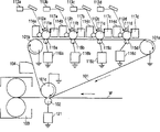
Fig. 4 represents the imaging device as background technology of the present invention.
This routine imaging device has: a plurality of photosensitive drums 111a, 111b, 111c, 111d, its corresponding respectively the 1st kind of color: yellow, the 2nd kind of color: magenta as the 1st picture supporting body, the 3rd kind of color: mazarine, the 4th kind of color: developer separately (toner) look of black; Intermediate transfer belt 101, this intermediate transfer belt 101 is as the 2nd contact with each photosensitive drums 111a~111d in separately primary transfer portion as supporting body.
So, each photosensitive drums 111a~111d disposes by following order successively along the moving direction of intermediate transfer belt 101: the photosensitive drums 111a that is positioned the 1st kind of color (yellow) of the top, be positioned the photosensitive drums 111b of the 2nd kind of color (magenta) the most nearby of this photosensitive drums 111a lower side, be positioned the photosensitive drums 111c of the 3rd kind of color (mazarine) the most nearby of this photosensitive drums 111b lower side, be positioned the photosensitive drums 111d of the 4th kind of color (black) the most nearby of this photosensitive drums 111c lower side.
In addition, intermediate transfer belt 101 carries out the rotation same period with each photosensitive drums 111a~111d with predetermined process speed.
Each photoreceptor 111a~111d is by each contact electrification roller 112a, 112b, 112c, 112d evenly electrifies, according to each modulated scanister 113a by the image information signal of host computer transmission, 113b, 113c, 113d penetrates laser, forms electrostatic latent image from the teeth outwards by this laser.
This electrostatic latent image is by the rotation arrival developer 114a separately of each photosensitive drums 111a~111d, 114b, 114c, the opposing part of 114d, supply with the toner and the development that have same polarity (being negative polarity in this example) electric charge with 111a~111d surface, thereby form developer picture (toner picture).Developer 114a~the 114d that installs among photosensitive drums 111a separately~111d is the binary visualization way, is overlapped in the development bias voltage that DC voltage forms by alternating current and carries out development work by applying.
The toner picture of the last formation of each photoreceptor 111a~111d is in intermediate transfer device 101 and the formed primary transfer roll gap separately of photosensitive drums 111a~111d, by to the primary transfer roller 115a that is connected in intermediate transfer belt 101 back sides, 115b, 115c, apply on the 115d by primary transfer bias generator 116a, 116b, 116c, the primary transfer bias voltage that 116d produced is needed on the intermediate transfer belt 101 thus.In the stage of the primary transfer roll gap by intermediate transfer belt and photoconductor drum 111d, finish the formation of 4 color images that on intermediate transfer belt 101, carry out, thereby finish the primary transfer operation.
Next, take out 1 page of transfer printing material M,, pass by separate roller 101c and the secondary transfer printing roll gap portion that forms as secondary transfer roller 2 crimping of transfer printing material via intermediate transfer belt 101 by there being illustrated connecting gear.At this moment, to secondary transfer roller 102 apply according to secondary transfer printing bias generator 121 that produce with the bias voltage toner opposite polarity, the toner picture from middle transfer belt by secondary transfer printing on transfer printing material M.
The transfer printing material M that carries fixing toner picture of sending out from secondary transfer printing roll gap portion arrives fixing device 103, thereby obtains the permanent fixation picture through adding hot extrusion.
As shown in Figure 2, be wrapped in the driven roller 101a in the intermediate transfer belt 101 in intermediate transfer belt is opened and is located at, support roller 101b is on 3 rollers of separate roller 101c.
As intermediate transfer belt 101, carbon is scattered in the polyimide, by surface impedance being adjusted into ρ s=1 * 10
12The middle impedance of Ω also can be decayed along with transfer printing process etc. is additional to electric charge on the transfer belt thereby the special electrical mechanisms of removing needn't be set.In addition, intermediate transfer belt 101 is 1000mm for girth, and thickness is the individual layer endless belt of 100um.
Be wound with the driven roller 101a of intermediate transfer belt 101, support roller 101b and separate roller 101c are the roller of 29.8mm for the external diameter that elastic layer metal-cored with the aluminum of 24.0mm and bed thickness 2.9mm constitutes.In addition, secondary transfer roller 102 is the roller of 33.0mm for the external diameter that rubber layer metal-cored with the aluminum of 14.0mm and bed thickness 9.5mm constitutes, and the hardness of roller is 26 ° (ASKER-C).
Is 6 * 10 about this routine intermediate transfer belt 101 for Young modulus
9N/m
2Single layer structure.In addition, for footprint pressure P (N/m about the intermediate transfer belt 101 of this routine secondary transfer roller 102
2) be 3.3 * 104N/m
2
If the longitudinal length by secondary transfer roller 102 is L (m), the roll-gap width of intermediate transfer belt 101 and secondary transfer roller 102 is W (m), is F[N for the contact pressure of the intermediate transfer belt 101 of secondary transfer roller 102], footprint pressure P (N/m then
2) be P=F/ (L * W).
In addition, coating printing ink and make it and transfer roll 102 connects on intermediate transfer belt 101 is attached to the width W that ink traces on the transfer roll 102 can draw roll gap by mensuration.The mensuration of the width of ink traces be pair roller central authorities, longitudinally the central 50mm of distance of symmetry two places and longitudinally two places of the central 100mm of distance of symmetry add up to 5 times mensuration, according to the width W of 5 times mean values decision roll gaps.In this example, L=0.30mm, F=50N, W=0.0050m.
In the imaging device of above-mentioned electrofax mode, on secondary transfer roller 102, adopt hardness be 26 ° (ASKER-C) thus the soft roller guarantee that the roll-gap width of secondary transfer roller 102 is 5.0mm, the stabilization that transmits by the transfer printing material that reaches like this in the secondary transfer printing operation, thus prevent to transmit fault and the generation of the image deflects that cause by the transfer printing material.
In addition, intermediate transfer belt 101 employing Young moduluss are 6 * 10
9N/m
2Thereby the high rigidity material prevent the destruction that the fracture etc. by band causes, therefore obtain the intermediate transfer belt of high life.
; as mentioned above; adopt the situation of the intermediate transfer belt 101 of high rigidity; because in case on the secondary transfer printing device, adopt the roller of soft that roll-gap width is broadened easily; so the footprint pressure P of secondary transfer roller 102 is set at low value, thereby cause having the situation of the color of image inequality that is caused by the secondary transfer printing operation to produce.
The irregular colour that produces during this secondary transfer printing operation can be thought what the convex-concave by transfer printing material surface caused.
That is to say because the convex-concave on the surface of transfer printing material M and the high rigidity of intermediate transfer belt, transfer printing material M surface can not closely contact equably with the surface of intermediate transfer belt 101, therefore, between the surface of transfer printing material M surface and intermediate transfer belt 101 along with there is the clearance in change in location.
Between toner layer on the intermediate transfer belt 101 and transfer printing material M surface, exist on the position of clearance, by only load on the transfer electric field of original toner layer with the air layer dividing potential drop, make load on color emission layer electric field die down, thereby the toner that causes remaining on the intermediate transfer rollers 101 becomes many.This is that because only otherwise polarity transformation takes place the transfer electric field that loads on color emission layer is big more, and the toning dosage to transfer printing material M transfer printing on the middle transfer belt 101 will become many reasons.
So, in case the contact conditions on transfer printing material M surface and intermediate transfer belt 101 surfaces are local when inhomogeneous, it is inhomogeneous that the transfer printing remaining toner also becomes.Can think and the difference that the position produced of the secondary transfer printing remaining toner in this secondary transfer printing operation cause the generation of image inequality.
Therefore, in the above-mentioned example, owing on secondary transfer roller, adopt the soft roller, make footprint pressure P become low value, the convex-concave on transfer printing material surface is difficult for echoing the surface of intermediate transfer belt 101 thus, thereby make the contact condition of transfer printing material M and intermediate transfer belt 101 become inhomogeneous, and then make the remaining toner on the intermediate transfer belt 101 also become inhomogeneous, cause the generation of irregular colour.
Summary of the invention
The purpose of this invention is to provide a kind of imaging device,, also can prevent image deterioration even this imaging device adopts the picture supporting body of high rigidity.
Other purpose of the present invention provides a kind of imaging device, this imaging device have load image the picture supporting body and with this as supporting body at the contacted transfer member of contact site, and should be needed on the transfer medium at this contact site by this transfer member as the image on the supporting body, this Young modulus as supporting body is 2 * 10
8[N/m
2]~9 * 10
9[N/m
2], be 4.0 * 10 at this of this contact site as the footprint pressure between supporting body and this transfer member
4[N/m
2]~7.3 * 10
4[N/m
2].
Other purpose of the present invention provides a kind of imaging device, picture supporting body and this that this imaging device has a load image as supporting body at the contacted transfer member of contact site, and should be needed on the transfer medium at this contact site by this transfer member as the image on the supporting body, this surface impedance as supporting body is 1 * 10
8[Ω]~1 * 10
15[Ω] is 4.0 * 10 at this of contact site as supporting body and the footprint pressure that changes between the transfer member
4[N/m
2]~7.3 * 10
4[N/m
2].
Other purpose of the present invention is illustrated hereinafter.
Description of drawings
Fig. 1 is the synoptic diagram as the imaging device of embodiments of the invention.
Fig. 2 is the skeleton view of secondary transfer printing portion.
Fig. 3 is the synoptic diagram of secondary transfer printing portion of other embodiment.
Fig. 4 is the synoptic diagram as the imaging device of background technology of the present invention.
Embodiment
Below, the imaging device as embodiments of the invention is described in detail with reference to accompanying drawing.
The 1st embodiment
As shown in Figure 1, adopt the summary section of very color electrophotographic imaging forming apparatus, the structure of the imaging device of present embodiment is illustrated.
Imaging device has: a plurality of photosensitive drums 11a, 11b, 11c, 11d, its corresponding respectively the 1st kind of color as the 1st picture supporting body: yellow, the 2nd kind of color: magenta, the 3rd kind of color: mazarine, the 4th kind of color: developer separately (toner) look of black; Intermediate transfer belt 1, it is as the 2nd contact with each photosensitive drums 11a~11d in separately primary transfer portion as supporting body.
Each photosensitive drums 11a~11d is configured in the following order along the moving direction of intermediate transfer belt 1: the photosensitive drums 11a of the 1st kind of color (yellow) is positioned the top; The photosensitive drums 11b of the 2nd kind of color (magenta) be positioned this photosensitive drums 11a lower side the most nearby; The photosensitive drums 11c of the 3rd kind of color (mazarine) be positioned this photosensitive drums 11b lower side the most nearby; The photosensitive drums 11d of the 4th kind of color (black) be positioned this photosensitive drums 11c lower side the most nearby.
Can adopt following material to make as intermediate transfer belt 1: urethanes resin, fluorine-type resin, nylon-based resin, resin flakes such as polyimide based resin as supporting body; Perhaps, thus on these resins, disperse carbon dust or conducting powder to carry out the adjusted resin flake of impedance; Perhaps, have, form organic elastomer thin slice on the toner carrier face of basic unit's thin slices such as NBR with multi-ply construction as the resin bed of release layer at urethanes rubber.
Employed intermediate transfer belt 1 is for disperseing carbon dust and its surface impedance is adjusted into ρ s=1 * 10 in poly-imines down in the present embodiment
12The middle impedance of Ω forms, and the special electrical mechanisms of removing need not be set just can decay and be carried in electric charge on the intermediate transfer belt 1 in the transfer printing process.In addition, this intermediate transfer belt 1 is girth 1000mm, the single layer of rings annular shape band of thickness 100um.
The mensuration of surface impedance is benchmark with JIS (Japanese IndustrialStandard) JIS-K6911, by with conducting rubber as electrode, make the surface of electrode and band have excellent contact, on this basis, adopt superelevation resistance impedometer (R8340 that ア De バ Application テ ス ト company makes) to measure.Condition determination is for applying voltage=100V, application time=30s.
In addition, the Young modulus E of the intermediate transfer belt 1 by present embodiment is 9 * 10
9N/m
2High rigidity, thereby can prevent to destroy or creep, thereby reach long lifetime.
The mensuration of Young modulus E is benchmark with the tensile elasticity rate assay method of JIS-K7127, and the thickness setting of measuring test portion is 100um.
Driven roller 1a, support roller 1b and separate roller 1c are metal-cored with the aluminum of diameter 24.0mm and the roller of the external diameter 29.8mm of the Hydrin rubber layer of bed thickness 2.9mm formation, by Hydrin rubber is carried out the impedance adjustment roller resistance value are set at 1 * 10
6Ω.
The roller resistance value is that the roller with determination object is connected on the aluminum cylinder of diameter 30mm and when making the driven rotation of aluminum cylinder, adopts superelevation resistance impedometer (R8340 that ア De バ Application テ ス ト company makes) to measure.Condition determination is for applying voltage=100V, application time=30s, contact pressure=9.8N, rotation round speed=117mm/s.
The intensity of laser and point of irradiation footpath are set by suitable normal incidence according to the resolution and the desired images concentration of imaging device, the part of irradiating laser is that (approximately-150V), remainder keeps (forming the electrostatic latent image on each photosensitive drums 11a~11d approximately-650V) by the dark portion current potential that plays electric forming as each contact electrification roller 12a~12d of an electrifier bright current potential VD.
Electrostatic latent image is by the rotation of each photosensitive drums 11a~11d, arrive the opposing part of developer 14a~14d separately, supply is with the developer (toner) that electrifies with the same polarity of photosensitive drum surface (being negative polarity in this example) and carry out development, thereby forms developer picture (toner picture) on the sense organ drum.
Be formed at the toner picture on each photosensitive drums 11a~11d, in the primary transfer roll gap 20a~20d separately of or abutment portion approaching with photosensitive drums 11a~11d as intermediate transfer device 1, by to the primary transfer roller 15a that is connected in intermediate transfer belt 1 back side, 15b, 15c, apply the primary transfer bias voltage that produced by primary transfer bias generator 16a~16d (carry out in this enforcement+15uA decide Current Control) on the 15d, be needed on the intermediate transfer belt 1.By the stage of intermediate transfer belt 1, finish the formation of 4 color images on intermediate transfer belt 1, thereby finish the primary transfer operation with the primary transfer roll gap 20d of photoconductor drum 11d.
On the one hand, by the bulging cleaning plant 17a that constitutes by the chemglaze scraping blade, 17b, 17c, thereby 17d removes primary transfer remaining toner etc. and makes surperficial peace and quietization of each photosensitive drums 11a~11d of the primary transfer of finishing the toner picture, thereby is ready for following imaging process.
Secondly, take out 1 page of transfer printing material M by there being illustrated connecting gear, this transfer printing material M is via intermediate transfer belt 1, is passed in formed secondary transfer printing roll gap portion 22 under separate roller 1c and the crimping effect as the secondary transfer roller 2 of transfer member.23 is the pressing mechanism of spring etc., by these pressing mechanism 23 secondary transfer roller 2 via being with 1 couple of separate roller 1c to push.Secondary transfer printing roll gap portion 22 is intermediate transfer portion and secondary transfer roller 2 contacted contact sites.
At this moment, to secondary transfer roller 2 apply according to secondary transfer printing bias generator 21 that produce with the bias voltage toner opposite polarity (carry out in the present embodiment+30uA decide Current Control control), make the toner picture from middle transfer belt 1 by secondary transfer printing on transfer printing material M.
Carry pass secondary transfer printing roll gap portion and not the transfer printing material M of the toner picture of photographic fixing arrive stationary installation 103, obtain the permanent fixation picture thereby it is added hot extrusion.Finish the surface that toner is looked like to be needed on the intermediate transfer belt 1 of transfer printing material M, remove the secondary transfer printing remaining toners by intermediate transfer body cleaning plant 4 with removing scraping blade of making by chemglaze.
As mentioned above, the intermediate transfer belt 1 that uses in the present embodiment is by carbon being scattered in the polyimide, surface impedance being adjusted into ρ s=1 * 10 again
12The middle impedance of Ω forms, thereby needn't being set, the special electrical mechanisms of removing also can decay along with transfer printing process etc. is additional to electric charge on the transfer belt, and in addition, be 9 * 10 by Young modulus E
9N/m
2High rigidity can prevent disrumpent feelings or creep, thereby reaches long lifetime.
In addition, secondary transfer roller 2 in the present embodiment is a roller metal-cored by the aluminum of diameter 14.0mm and the external diameter 22.0mm that foaming Hydrin rubber layer bed thickness 4mm constitutes, by Hydrin rubber is carried out the impedance adjustment roller resistance value is set at 1 * 10
8Ω.In addition, using the hardness of secondary transfer printing device is the roller of the soft slightly of 35 ° (ASKER-C), can prevent to impact the generation that transmits the image deflects that cause because of the transmission of transfer printing material by widening the roll-gap width of secondary transfer roller 2.
That is to say, the imaging device of present embodiment adopts the picture supporting body of high rigidity and the transfer member of soft, though can improve the convective performance of transfer printing material, realize long lifetime, but the imaging device of the picture supporting body of this transfer member with soft and high rigidity, as described in the background art, owing to the footprint pressure step-down of transfer member, be easy to generate the irregular colour of image.
In the present embodiment, the footprint pressure of the intermediate transfer belt 1 of secondary transfer roller 2 is P (N/m
2) be 4.8 * 10
4N/m
2The contact pressure of 102 pairs of middle transfer belt 101 of secondary transfer roller is F[N], and the longitudinal length of secondary transfer roller 2 is L (m), the width of the roll gap of intermediate transfer belt 1 and secondary transfer roller 2 is W (m), then (the L * W) of the footprint pressure P=F/ of transfer belt 101 in the middle of 102 pairs of the secondary transfer roller.(with reference to Fig. 2)
In addition, coating printing ink and connect with secondary transfer roller 2 on intermediate transfer belt 1 is attached to the width W that ink traces on the secondary transfer roller 2 can draw roll gap by mensuration.As its assay method, the mensuration of the width of ink traces be pair roller central authorities, longitudinally the central 50mm of distance of symmetry two places and longitudinally two places of the central 100mm of distance of symmetry add up to 5 times mensuration, according to the width W of 5 times mean values decision roll gaps.In the present embodiment, L=0.30mm, F=80N, W=0.0056m.
Here, according to the structure of the experimental example 1~7 that changes various conditions, can confirm the effect of present embodiment.In the experimental example 1~7, in imaging device, for the footprint pressure P[N/m of secondary transfer roller to middle transfer belt
2] and the numerical value of the Young modulus of intermediate transfer belt changed.In addition, experimental example 4 is the situation (embodiment 1) of present embodiment.
From 2.7 * 10
4N/m
2To 8.0 * 10
4N/m
2Change footprint pressure P.This footprint pressure P obtains by changing following key element: change contact pressure F [N] by from 30 to 100, change the material hardness of the rubber layer of secondary transfer roller in addition once more, and establish the width W that 35 ° of hardness with the roller of 49 ° of (ASKER-C) two kinds of benchmark change roll gap by employing.
Table 1 has been enumerated the footprint pressure P of corresponding each experimental example, contact pressure F, roll-gap width W, the data of the setting of secondary transfer roller hardness.These numerical value are measured according to the assay method of the foregoing description 1.
Table 1
| Secondary transfer roller hardness [°] (ASKER-C) | Contact pressure F [N] | Transfer nip width W [mm] | Footprint pressure P[N/m 2] | |
| Experimental example 1 | ?35 | ?30 | ?3.4 | ?2.7×10 4 |
| Experimental example 2 | ?35 | ?50 | ?4.5 | ?3.5×10 4 |
| Experimental example 3 | ?35 | ?60 | ?5.0 | ?4.0×10 4 |
| Experimental example 4 | ?35 | ?80 | ?5.6 | ?4.8×10 4 |
| Experimental example 5 | ?49 | ?70 | ?4.0 | ?6.2×10 4 |
| Embodiment 6 | ?49 | ?90 | ?4.8 | ?7.3×10 4 |
| Embodiment 7 | ?49 | ?100 | ?5.1 | ?8.0×10 4 |
On the one hand, in these conditions, by with the material of intermediate transfer belt from 4 * 10
6Change to 9 * 10
9Change the Young modulus of intermediate transfer belt.
Experimental example 1~7 separately as described above, intermediate transfer belt adopts following material respectively: the Young modulus E that 1. carbon is scattered in the polyimide is 9 * 10
9Material, 2. Young modulus is 2 * 10
8The material of Kynoar (PVDF), 3. Young modulus is 2 * 10
9N/m
2The material of polyethersulfone resin (PES).
In addition, especially for the carrying material that hangs down Young modulus, as individual layer because band flexible or produce creep and easily cause image multiplying power instability, so and owing to destroy and the also very short function that can not satisfy of life-span easily as intermediate transfer belt, therefore, 4. adopt by on the thick sheet rubber of the 3mm of NBR, covering urethane resin and form double-deck band (urethane resin covering), it is installed on its imaging device separately by spray application.The Young modulus of urethane resin layer is 4 * 10
6N/m
2
2. PVDF band and the band of PES 3. are ρ s=1 * 10 by disperseing the impedance of carbon dust adjustment form face
12Ω, and form girth 1000mm, the single layer of rings shape band of thickness 100um.In addition, urethane resin coated tape 4. is 1 * 10 by the volume impedance that disperses carbon dust to adjust NBR
6Ω cm, cover again 30um thick to pass through the volume impedance be 1 * 10
9The urethane resin of Ω cm, the surface impedance ρ s that forms toner loading end side is 1 * 10
12Ω and girth are 1000mm, and thickness is the annular shape band of 2 layers of 500um.
In each test, carry out image quality and dependence footprint pressure P and with the dependent detection of Young modulus E.Table 2 has been enumerated the image testing result relatively about test example 1~7.
Table 2
Image quality evaluation result (irregular colour level/decolouring level)
| Footprint pressure P[N/m 2] | The Young modulus E[N/m of intermediate transfer belt 2] | ||||
| 4×10 6 | 2×10 8 | 2×10 9 | 9×10 9 | ||
| Experimental example 1 | ?2.7×10 4 | △/○ | ×/○ | ×/○ | ×/○ |
| Experimental example 2 | ?3.5×10 4 | ○/○ | ○/○ | ○/○ | ×/○ |
| Experimental example 3 | ?4.0×10 4 | ○/○ | ○/○ | ○/○ | △/○ |
| Experimental example 4 | ?4.8×10 4 | ○/○ | ○/○ | ○/○ | ○/○ |
| Experimental example 5 | ?6.2×10 4 | ○/○ | ○/○ | ○/○ | ○/○ |
| Experimental example 6 | ?7.3×10 4 | ○/○ | ○/△ | ○/△ | ○/△ |
| Experimental example 7 | ?8.0×10 4 | ○/○ | ○/× | ○/× | ○/× |
The evaluation of the uneven level of color of image during the irregular colour of the rich fish diagram picture by estimating blueness (pinkish red and blue or green) carry out table 2, in addition, the decolour evaluation of image level of the decolouring of the line image that the 2mm of blue according to estimating (pinkish red and blue or green) is wide.Carry out the judgement of uneven level of above-mentioned color of image and decolouring according to the sensory evaluation of observing with eyes, judgment standard is, zero=do not produce, and the practical level of △=do not influence, *=can know the level of resolution.
According to this detection, can improve the color of image inequality though improve footprint pressure, the too high decolouring image that will produce of footprint pressure P produces.Young modulus is got over the hi-vision irregular colour and will be worsened in addition.
Here, be illustrated being known as color of image phenomenon uneven and the decolouring image.
(1) color of image inequality: color of image is not mainly by win the observed significantly phenomenon that goes out of fish diagram picture as blue, red, green binary color.For example blue, constitute the blue magenta and the state of navy blue toner picture overlapping mazarine toner on the toner that is formed on magenta on the intermediate transfer belt.
Here on the magenta toner overlapping mazarine toner because magenta toner plays effect as the liner particle for intermediate transfer belt, so roughly be needed on equably on the transfer printing material.On the other hand, the magenta toner below mazarine toner on this intermediate transfer belt is owing to the adhesion of magenta toner and intermediate transfer interband residues in the toner of a part on the intermediate transfer belt in the secondary transfer printing operation.
This magenta remaining toner also can become inhomogeneous for the magenta composition in the rich fish diagram picture of the final blueness on the uniform transfer printing material roughly in case produce inhomogeneously with the position.Therefore, exist near navy blue field in the blue optimized image, be regarded as irregular colour.
That is to say that the color of image inequality is in a plurality of toner picture that overlaps to form on intermediate transfer belt, only the toner with the color of part surface side looks like to be needed on the transfer printing material, thereby forms the phenomenon of irregular colour.
Below, this irregular colour and footprint pressure P are had the mechanism of interdependence, the present invention does following consideration.
The reason that irregular colour produces is because according to the convex-concave on transfer printing material surface, makes between transfer printing material surface and intermediate transfer belt surface evenly and closely to contact, cause the transfer printing material surperficial with the intermediate transfer belt surface between along with the position is different and have a clearance.
Only otherwise produce the polarity reversal of toner, the transfer electric field that loads on the toner layer is big more, and the toning dosage that is transferred on the transfer printing material from middle transfer belt is many more.
Bad on transfer printing material surface with contacting of central transfer surface, and make the position that has the clearance between toner layer on the intermediate transfer belt and transfer printing material surface, since the transfer electric field that loads on original toner layer with air layer by dividing potential drop, die down so load on the electric field of toner layer, thereby the toner that causes residuing on the intermediate transfer belt becomes many.Think because the contact condition of transfer printing material surface and intermediate transfer belt surface along with the position becomes inhomogeneous, makes the transfer printing remaining toner also become inhomogeneous according to these.
Therefore, in the present embodiment, eliminate the convex-concave on transfer printing material surface, make the transfer printing material M surface and the contact condition on intermediate transfer belt 1 surface become even by improving footprint pressure P, make by making remaining toner on the intermediate transfer belt become all even, thereby improve irregular colour.
In addition, do following consideration for the mechanism of the Young modulus E interdependence of irregular colour.
The reason that irregular colour produces as mentioned above, is because according to the convex-concave on transfer printing material surface, and transfer printing material surface and intermediate transfer belt surface can not be evenly and the reason that closely contacts.
Because the Young modulus height of intermediate transfer belt, the surface of intermediate transfer belt is hard, and the intermediate transfer belt surface element echos the convex-concave on hard material surface, forms the clearance between color emission layer on the intermediate transfer belt on the field of large scale more and transfer printing material surface.According to these, the Young modulus of intermediate transfer belt is high more, and irregular colour worsens more.
2 decolouring images: the decolouring image be main with as the observed significantly phenomenon of blue, red, green binary color line image.
Constitute blue magenta and navy blue toner to the mazarine toner being overlapped in state on the pinkish red toner being formed with on the intermediate transfer belt.In the secondary transfer printing operation, in the pinkish red toner on the lid intermediate transfer belt below the mazarine toner, mainly the central portion with line image residues on the intermediate transfer belt, mazarine toner on the final line image on the transfer printing material is roughly even thus, as not being, the online central portion of magenta toner tails off.Thus, exist on the central portion of blue line image and approach navy blue field, thereby the central portion that is regarded as line image decolours.
Especially on the line image central portion remaining toner too much be because toner under by the compressed situation of the clamp pressure between transfer printing material and the intermediate transfer belt, on the toner of line central portion, load the pressure maximum, cause the adhesion of the toner of central portion to become high especially.
Mechanism for the footprint pressure interdependence of decolouring image is done as following consideration.The reason that decolouring produces is because by the clamp pressure compression toner with transfer printing material and intermediate transfer belt, the adhesion of same toner increases, and because the high more same toner adhesion of footprint pressure increases more, the decolouring image level worsens.
In addition, on intermediate transfer belt, adopting low Young modulus material, the just necessary sandwich construction that adopts, this makes that manufacturing of band is complicated, cause with cost improve.
Therefore, the invention is characterized in, for reaching the long-life, cost degradation uses the intermediate transfer belt of high rigidity, does not reduce the Young modulus E of intermediate transfer belt, by suitably adjusting the value of footprint pressure, thereby prevent aforesaid irregular colour or decolouring phenomenon.
Therefore, according to above-mentioned relatively testing result shown in the table 2, confirm experimental example 3~6 for irregular colour, decolouring produces effect, and has because footprint pressure P is set at 4.0 * 10
4[N/m
2]≤P≤7.3 * 10
4[N/m
2] scope in, be 2 * 10 at the Young modulus E of intermediate transfer belt 1
8[N/m
2]≤E≤9 * 10
9[N/m
2] situation under, can be reduced irregular colour and the decolouring image the generation level, prevent the effect that image is bad.
So in the present embodiment, E is set at 2 * 10 with Young modulus
8[N/m
2]≤E≤9 * 10
9[N/m
2], footprint pressure P is set at 4.0 * 10
4[N/m
2]≤P≤7.3 * 10
4[N/m
2] scope in.
According to these present embodiment, Young modulus E is 2 * 10
8[N/m
2]≤E≤9 * 10
9[N/m
2], and, can reach long-life and low cost by adopting the intermediate transfer belt of high rigidity, even adopt the intermediate transfer belt of this high rigidity in addition, be set in 4.0 * 10 by footprint pressure P with intermediate transfer belt and transfer member
4[N/m
2]≤P≤7.3 * 10
4[N/m
2] scope in, thereby can prevent that also images such as irregular colour or decolouring are bad.
" embodiment 2 "
Below, embodiments of the invention 2 are described.Basic and the embodiment 1 of embodiment 2 has same structure, and the part to different structure describes here.
As shown in Figure 4, in the present embodiment,, adopt carbon is scattered in the polyimide, and the toner loading end is adjusted into surface impedance with its rear side is ρ s=1 * 10 as intermediate transfer belt 24
12The girth of Ω is 1000mm, and thickness is the single layer of rings shape band of 100um.
In addition, the Young modulus E of the intermediate transfer belt 24 of present embodiment is 9 * 10
9N/m
2
Footprint pressure P[N/m for the intermediate transfer belt 24 of secondary transfer roller 2
2] be 4.8 * 10 similarly to Example 1
4N/m
2
Here, in the experimental example 8~14, change the surface impedance of secondary transfer roller to the footprint pressure and the intermediate transfer belt of middle transfer belt.With footprint pressure from 2.7 * 10
4Be changed to 8.0 * 10
4N/m
2Experimental example 11 is present embodiment (embodiment 2) in addition.
Each is tested in the example, identical with the situation of experimental example 1~7, footprint pressure F[N] be changed to 100[N from 30], the material hardness of the rubber layer by changing secondary transfer roller 2 and be 35 ° of two kinds of firmness levels with 49 ° (ASKER-C) by adopting hardness is regulated footprint pressure P with this in addition.
In addition, be scattered in carbon dust amount in the polyimide by adjustment, with the surface impedance ρ s of intermediate transfer belt from 1 * 10
6Be changed to 1 * 10
15More than the Ω.
Here, because surface impedance ρ s is 1 * 10
15The above surface impedance that intermediate transfer belt had has exceeded as 1 * 10 of the mensuration boundary that ground noise determined of being measured system by above-mentioned surface impedance
15More than the Ω, therefore it is recorded as 1 * 10
15More than the Ω.In addition, surface impedance is measured according to the method for explanation among the embodiment 1.
It is 1000mm that the intermediate transfer belt of each experimental example is all girth mutually with present embodiment, and thickness is the individual layer endless belt of 100um.
In the experimental example 8~14, the footprint pressure P interdependence and the surface impedance ρ s interdependence of image quality detected.Table 3 has been enumerated the comparison testing result about the image of each experimental example.
Table 3
| Image quality evaluation result (irregular colour level/decolouring level) | |||||||
| Footprint pressure P[N/m 2] | Surface impedance ρ s[Ω] | ||||||
| ??1×10 6 | ??1×10 8 | ??1×10 10 | ??1×10 12 | ??1×10 14 | ??1×10 15More than | ||
| Experimental example 8 | ??2.7×10 4 | ??×/○ | ??×/○ | ??×/○ | ??×/○ | ??×/○ | ??×/○ |
| Experimental example 9 | ??3.5×10 4 | ??×/○ | ??×/○ | ??×/○ | ??×/○ | ??△/○ | ??○/○ |
| Experimental example 10 | ??4.0×10 4 | ??△/○ | ??○/○ | ??○/○ | ??○/○ | ??○/○ | ??○/○ |
| Experimental example 11 | ??4.8×10 4 | ??△/○ | ??○/○ | ??○/○ | ??○/○ | ??○/○ | ??○/○ |
| Experimental example 12 | ??6.2×10 4 | ??○/△ | ??○/○ | ??○/○ | ??○/○ | ??○/○ | ??○/○ |
| Experimental example 13 | ??7.3×10 4 | ??○/× | ??○/△ | ??○/△ | ??○/△ | ??○/△ | ??○/△ |
| Experimental example 14 | ??8.0×10 4 | ??○/× | ??○/× | ??○/× | ??○/× | ??○/× | ??○/× |
According to this detection, improve the footprint pressure irregular colour and improve, the high more irregular colour of the surface impedance ρ s of intermediate transfer belt becomes good more.
In addition, 1 * 10
6The intermediate transfer belt of Ω, even improve footprint pressure, the irregular colour and the decolouring that can not solve well simultaneously.
In addition, 1 * 10
15The intermediate transfer belt that Ω is above, because the charge decay time coefficient is very big, the residual electric charge that is endowed of meeting on the surface, when forming image, the position of the upstream side of the photosensitive drums 11a of the downstream side of the cleaning scraping blade 4 on intermediate transfer belt and the 1st kind of color is provided with no illustrated corona electrifier, by loading 10kVpp, 1kHz, sinusoidal wave AC bias forms except that carrying out image in the electricity on intermediate transfer belt.
It is identical with embodiment 1 to carry out the uneven judgement with decolouring of color of image in the table 3.To the mechanism of the surface impedance ρ s interdependence of this irregular colour, the present inventor does following consideration.
The reason that irregular colour produces is because the convex-concave on transfer printing material surface makes between transfer printing material surface and intermediate transfer belt surface can not closely contact equably, cause the position that has the clearance between transfer printing material surface and intermediate transfer belt surface, the toner that residues on the intermediate transfer belt is too much.
By improving surface impedance ρ s, the difference of the transfer electric field that loads on the field that the clearance can be existed and the toner layer in non-existent field diminishes, thereby can reduce the field of clearance existence and the amount of the remaining toner on the non-existent field.By like this, residual toner becomes evenly on the intermediate transfer belt, thereby improves irregular colour.
According to above-mentioned testing result, experimental example 10~13 is for irregular colour, and decolouring produces effect, as the surface impedance ρ of middle transfer belt s[Ω] be 1 * 10
8[Ω]≤ρ s≤1 * 10
15Under the situation of [Ω], by with footprint pressure P[N/m
2] be set at 4.0 * 10
4[N/m
2]≤P≤7.3 * 10
4[N/m
2] scope in, when not having special intermediate transfer belt neutralizer, can guarantee that the generation level of irregular colour and decolouring image can not cause the problem that produces in the practicality.
So, in the present embodiment, with the surface impedance ρ s[Ω of intermediate transfer belt 24] and be set at 1 * 10
8[Ω]≤ρ s≤1 * 10
15In the scope of [Ω], with footprint pressure P[N/m
2] be set at 4.0 * 10
4[N/m
2]≤P≤7.3 * 10
4[N/m
2] scope in.
In addition, as described in example 1 above, in the present embodiment, even intermediate transfer belt Young modulus E is 2 * 10
8≤ E≤9 * 10
9High rigidity, also can suppress the generation of irregular colour and decolouring.
In addition, though the foregoing description is illustrated the intermediate transfer belt of individual layer, the present invention also goes for having at least the multilayer intermediate transfer belt of the Young modulus of high rigidity on the superficial layer of transfer printing portion side.
In the foregoing description, to have the color laser printer as the photosensitive drums of supporting body that divides as 4 looks for imaging device is that example is illustrated, but the present invention is not limited only to this example, also can be used for facsimile unit, the imaging device of duplicating machine device etc., photosensitive drums also can be 1 in addition.In addition, be not limited only to colour, also applicable to having 1 imaging device as the monochrome of supporting body.
In addition, in the foregoing description, to utilizing as intermediate transfer belt as supporting body, and utilize as being formed the secondary transfer roller that picture is transferred to the transfer member on the transfer printing material, situation on from middle transfer belt secondary transfer printing to the transfer printing material is illustrated, but is not limited only to this, also applicable to utilizing as the sense organ drum as supporting body, the sensitization band is needed on other the medium such as transfer printing material or intermediate transfer body being formed picture.Therefore, in the imaging device that does not possess the intermediate transfer body, also be suitable for.
Described in embodiment 1 and embodiment 2, by with the transfer member of transfer roll etc. with as the footprint pressure P[N/m that looks like supporting body of intermediate transfer belt
2] be set at 4.0 * 10
4[N/m
2]≤P≤7.3 * 10
4[N/m
2], use the long-life and, also can prevent the image processing system of irregular colour or decolouring even can provide cheaply as supporting body and transfer member.So this situation is even the surface impedance of picture supporting body also can prevent decolouring or irregular colour than higher.
As mentioned above, imaging device of the present invention is widely applicable for picture supporting body or transfer member, even use the picture supporting body of high rigidity, also can prevent irregular colour or image decolouring in the imaging process, thereby low-cost and long-life imaging device can be provided.
More than, embodiments of the invention are illustrated, but the present invention is not limited only to the foregoing description, also be included in a shear deformation of being done in the technological thought of the present invention.
Claims (13)
1. imaging device, its have load image the picture supporting body and with above-mentioned picture supporting body at the contacted transfer member of contact site, above-mentionedly be needed on the transfer medium at above-mentioned contact site by above-mentioned transfer member as the image on the supporting body, the Young modulus of above-mentioned picture supporting body is 2 * 10
8[N/m
2]~9 * 10
9[N/m
2] scope in, at the above-mentioned picture supporting body of above-mentioned contact site and the footprint pressure between the above-mentioned transfer member 4.0 * 10
4[N/m
2]~7.3 * 10
4[N/m
2] scope in.
2. imaging device as claimed in claim 1, above-mentioned picture supporting body is band.
3. imaging device as claimed in claim 2, above-mentioned band are individual layer.
4. imaging device as claimed in claim 2 has via above-mentioned band and above-mentioned transfer member parts in opposite directions in opposite directions, and above-mentioned parts are in opposite directions supported above-mentioned band.
5. imaging device as claimed in claim 1, above-mentioned picture supporting body is the intermediate transfer body, above-mentioned transfer medium is above-mentioned transfer printing material.
6. imaging device as claimed in claim 1, the surface impedance of above-mentioned picture supporting body are 1 * 10
8[Ω]~1 * 10
15[Ω].
7. imaging device as claimed in claim 1, above-mentioned picture supporting body is a photosensitive drums, above-mentioned transfer medium is intermediate transfer body or transfer printing material.
8. imaging device, its have load image the picture supporting body and with above-mentioned picture supporting body at the contacted transfer member of contact site, above-mentionedly be needed on the transfer medium at above-mentioned contact site by above-mentioned transfer member as the image on the supporting body, the surface impedance of above-mentioned picture supporting body is 1 * 10
8[Ω]~1 * 10
15In the scope of [Ω], at the above-mentioned picture supporting body of above-mentioned contact site and the footprint pressure between the above-mentioned transfer member 4.0 * 10
4[N/m
2]~7.3 * 10
4[N/m
2] scope in.
9. imaging device as claimed in claim 8, above-mentioned picture supporting body is band.
10. imaging device as claimed in claim 9, above-mentioned band are individual layer.
11. imaging device as claimed in claim 9 has via above-mentioned band and above-mentioned transfer member parts in opposite directions in opposite directions, above-mentioned parts are in opposite directions supported above-mentioned band.
12. imaging device as claimed in claim 8, above-mentioned to hold as supporting body be the intermediate transfer body, and above-mentioned transfer medium is above-mentioned transfer printing material.
13. imaging device as claimed in claim 8, above-mentioned picture supporting body is a photosensitive drums, and above-mentioned transfer medium is intermediate transfer body or transfer printing material.
Applications Claiming Priority (2)
| Application Number | Priority Date | Filing Date | Title |
|---|---|---|---|
| JP221515/2002 | 2002-07-30 | ||
| JP2002221515A JP2004061941A (en) | 2002-07-30 | 2002-07-30 | Image forming apparatus |
Publications (1)
| Publication Number | Publication Date |
|---|---|
| CN1480794A true CN1480794A (en) | 2004-03-10 |
Family
ID=31941804
Family Applications (1)
| Application Number | Title | Priority Date | Filing Date |
|---|---|---|---|
| CNA031498965A Pending CN1480794A (en) | 2002-07-30 | 2003-07-30 | Imaging device |
Country Status (3)
| Country | Link |
|---|---|
| US (1) | US7043183B2 (en) |
| JP (1) | JP2004061941A (en) |
| CN (1) | CN1480794A (en) |
Cited By (1)
| Publication number | Priority date | Publication date | Assignee | Title |
|---|---|---|---|---|
| CN100511017C (en) * | 2004-03-26 | 2009-07-08 | 佳能株式会社 | Image forming apparatus preventing misregistration |
Families Citing this family (18)
| Publication number | Priority date | Publication date | Assignee | Title |
|---|---|---|---|---|
| US7381515B2 (en) * | 2004-04-26 | 2008-06-03 | Canon Kabushiki Kaisha | Image forming method and image forming apparatus |
| JP4671392B2 (en) * | 2004-07-16 | 2011-04-13 | 株式会社リコー | Full-color image forming method, full-color image forming apparatus, and full-color toner |
| JP2006113285A (en) * | 2004-10-14 | 2006-04-27 | Sharp Corp | Color image forming apparatus |
| JP2006138967A (en) * | 2004-11-11 | 2006-06-01 | Ricoh Co Ltd | Image forming apparatus |
| US7943224B2 (en) * | 2005-02-25 | 2011-05-17 | Oki Data Corporation | Endless belt, belt device and image forming apparatus |
| JP5081428B2 (en) * | 2005-12-08 | 2012-11-28 | 株式会社リコー | Image forming apparatus |
| JP2007199267A (en) * | 2006-01-25 | 2007-08-09 | Fuji Xerox Co Ltd | Full color image forming method |
| JP4730235B2 (en) * | 2006-07-13 | 2011-07-20 | 富士ゼロックス株式会社 | Image forming apparatus |
| JP2008275821A (en) * | 2007-04-27 | 2008-11-13 | Brother Ind Ltd | Image forming apparatus |
| US8023846B2 (en) * | 2007-06-07 | 2011-09-20 | Eastman Kodak Company | Segmented roller for flood coating system |
| JP4562147B2 (en) * | 2007-09-26 | 2010-10-13 | 株式会社沖データ | Image forming apparatus |
| JP5078570B2 (en) * | 2007-11-22 | 2012-11-21 | キヤノン株式会社 | Image forming apparatus |
| JP5407400B2 (en) * | 2009-02-17 | 2014-02-05 | 株式会社リコー | Image forming apparatus |
| JP2010217258A (en) * | 2009-03-13 | 2010-09-30 | Ricoh Co Ltd | Image forming device |
| JP5448991B2 (en) | 2010-04-14 | 2014-03-19 | キヤノン株式会社 | Image forming apparatus |
| JP5864867B2 (en) | 2011-02-10 | 2016-02-17 | キヤノン株式会社 | Image forming apparatus |
| JP2014126620A (en) * | 2012-12-25 | 2014-07-07 | Canon Inc | Image forming apparatus and intermediate transfer body |
| JP6866689B2 (en) * | 2017-02-28 | 2021-04-28 | コニカミノルタ株式会社 | Image forming device |
Family Cites Families (8)
| Publication number | Priority date | Publication date | Assignee | Title |
|---|---|---|---|---|
| US5728496A (en) * | 1996-05-24 | 1998-03-17 | Eastman Kodak Company | Electrostatographic apparatus and method for improved transfer of small particles |
| JPH10698A (en) | 1996-06-17 | 1998-01-06 | Fuji Xerox Co Ltd | Endless belt for image forming apparatus, the image forming apparatus and its manufacture |
| US6397034B1 (en) * | 1997-08-29 | 2002-05-28 | Xerox Corporation | Fluorinated carbon filled polyimide intermediate transfer components |
| US6246845B1 (en) * | 1998-03-30 | 2001-06-12 | Kabushiki Kaisha Toshiba | Electrophotographic machine including a backup roller disposed within an intermediate transfer medium |
| US6253038B1 (en) * | 1998-08-31 | 2001-06-26 | Canon Kabushiki Kaisha | Image apparatus having an improved intermediate transfer system |
| JP4806845B2 (en) * | 2000-01-07 | 2011-11-02 | 富士ゼロックス株式会社 | Semiconductive belt, semiconductive roll, and image forming apparatus |
| US20010028815A1 (en) * | 2000-03-23 | 2001-10-11 | Shougo Sato | Color image forming apparatus |
| US6389242B1 (en) * | 2000-09-15 | 2002-05-14 | Toshiba Tec Kabushiki Kaisha | Image forming apparatus and image forming method |
-
2002
- 2002-07-30 JP JP2002221515A patent/JP2004061941A/en active Pending
-
2003
- 2003-07-25 US US10/626,534 patent/US7043183B2/en not_active Expired - Fee Related
- 2003-07-30 CN CNA031498965A patent/CN1480794A/en active Pending
Cited By (1)
| Publication number | Priority date | Publication date | Assignee | Title |
|---|---|---|---|---|
| CN100511017C (en) * | 2004-03-26 | 2009-07-08 | 佳能株式会社 | Image forming apparatus preventing misregistration |
Also Published As
| Publication number | Publication date |
|---|---|
| US20040208678A1 (en) | 2004-10-21 |
| US7043183B2 (en) | 2006-05-09 |
| JP2004061941A (en) | 2004-02-26 |
Similar Documents
| Publication | Publication Date | Title |
|---|---|---|
| CN1480794A (en) | Imaging device | |
| CN1119717C (en) | Image forming apparatus | |
| JP5094242B2 (en) | Image forming apparatus | |
| CN1959559A (en) | Image forming apparatus and guide therefor capable of reducing toner scattered on recording medium | |
| US20110299866A1 (en) | Image forming apparatus | |
| CN101055458A (en) | Image forming apparatus | |
| US20080038017A1 (en) | Method and apparatus for image forming for effectively charging an image carrier | |
| EP3062157B1 (en) | Image forming apparatus | |
| JP2008281847A (en) | Image forming apparatus | |
| CN1148612C (en) | Image forming device | |
| CN101055456A (en) | Image forming apparatus and intermediate transfer member | |
| JPWO2016067840A1 (en) | Image forming apparatus | |
| CN1320411C (en) | Image forming apparatus | |
| JP2012118449A (en) | Charging member | |
| US9915889B2 (en) | Image forming apparatus | |
| JP4285426B2 (en) | Color image forming apparatus | |
| JP6020368B2 (en) | Image forming apparatus | |
| JP2008134393A (en) | Image forming apparatus | |
| CN1763642A (en) | Image forming apparatus | |
| JP2007079286A (en) | Image forming apparatus and process cartridge to be used for the same | |
| JP5002959B2 (en) | Semiconductive belt and image forming apparatus provided with the semiconductive belt | |
| US10620571B2 (en) | Image carrier and image forming apparatus | |
| US20160187817A1 (en) | Transfer-and-transport device and image forming apparatus | |
| JP2011107532A (en) | Charging device and image forming apparatus | |
| JP5870541B2 (en) | Transfer belt and image forming apparatus |
Legal Events
| Date | Code | Title | Description |
|---|---|---|---|
| C06 | Publication | ||
| PB01 | Publication | ||
| C10 | Entry into substantive examination | ||
| SE01 | Entry into force of request for substantive examination | ||
| C02 | Deemed withdrawal of patent application after publication (patent law 2001) | ||
| WD01 | Invention patent application deemed withdrawn after publication |