CN1431963A - Wind driven boat - Google Patents
Wind driven boat Download PDFInfo
- Publication number
- CN1431963A CN1431963A CN01810441A CN01810441A CN1431963A CN 1431963 A CN1431963 A CN 1431963A CN 01810441 A CN01810441 A CN 01810441A CN 01810441 A CN01810441 A CN 01810441A CN 1431963 A CN1431963 A CN 1431963A
- Authority
- CN
- China
- Prior art keywords
- ship
- thin
- wall member
- pressure gas
- hull
- Prior art date
- Legal status (The legal status is an assumption and is not a legal conclusion. Google has not performed a legal analysis and makes no representation as to the accuracy of the status listed.)
- Pending
Links
Images


Classifications
-
- B—PERFORMING OPERATIONS; TRANSPORTING
- B63—SHIPS OR OTHER WATERBORNE VESSELS; RELATED EQUIPMENT
- B63H—MARINE PROPULSION OR STEERING
- B63H9/00—Marine propulsion provided directly by wind power
- B63H9/04—Marine propulsion provided directly by wind power using sails or like wind-catching surfaces
- B63H9/06—Types of sail; Constructional features of sails; Arrangements thereof on vessels
- B63H9/069—Kite-sails for vessels
-
- B—PERFORMING OPERATIONS; TRANSPORTING
- B63—SHIPS OR OTHER WATERBORNE VESSELS; RELATED EQUIPMENT
- B63B—SHIPS OR OTHER WATERBORNE VESSELS; EQUIPMENT FOR SHIPPING
- B63B35/00—Vessels or similar floating structures specially adapted for specific purposes and not otherwise provided for
- B63B2035/009—Wind propelled vessels comprising arrangements, installations or devices specially adapted therefor, other than wind propulsion arrangements, installations, or devices, such as sails, running rigging, or the like, and other than sailboards or the like or related equipment
-
- Y—GENERAL TAGGING OF NEW TECHNOLOGICAL DEVELOPMENTS; GENERAL TAGGING OF CROSS-SECTIONAL TECHNOLOGIES SPANNING OVER SEVERAL SECTIONS OF THE IPC; TECHNICAL SUBJECTS COVERED BY FORMER USPC CROSS-REFERENCE ART COLLECTIONS [XRACs] AND DIGESTS
- Y02—TECHNOLOGIES OR APPLICATIONS FOR MITIGATION OR ADAPTATION AGAINST CLIMATE CHANGE
- Y02T—CLIMATE CHANGE MITIGATION TECHNOLOGIES RELATED TO TRANSPORTATION
- Y02T70/00—Maritime or waterways transport
- Y02T70/50—Measures to reduce greenhouse gas emissions related to the propulsion system
- Y02T70/5218—Less carbon-intensive fuels, e.g. natural gas, biofuels
- Y02T70/5236—Renewable or hybrid-electric solutions
Abstract
The invention relates to a wind-propelled watercraft by means of which in contrast to the conventional solutions the wind forces can be better utilized for the propulsion, and the turning moments about the longitudinal axis acting on the body of the watercraft and the hull, respectively can be reduced. With this, a sheet element is held with at least one stay rope in close proximity to the body of the watercraft, and the one or else a plurality of stay ropes are attached to at least three points of the sheet element spaced to one another. In addition, the point of application of force of the one or else a plurality of stay ropes on the body of the watercraft can be varied depending on the wind direction and direction of motion.
Description
This invention relates to wind driven boat, on this wind driven boat, have at least a thin-wall member be by at least one hull guy rope particularly the guy rope on the hull control.The present invention is particluarly suitable for using separately on sailing boat and other ship, and perhaps the traditional type of drive with other is used in combination.
Up to now, the sail that the actuating device of the ship and other the vehicle uses one or more textile material to make comes wind energy is utilized, and this is very general thing, and these sails all are fixed at least one mast and boom or the spar.These sails will be adjusted according to the direction of wind or with required travel direction, can utilize a part of wind energy at least, just can only provide the part in whole wind energies to produce propulsive force usually.
But, use the actuating device of this form, can produce torque in the longitudinal axis direction of assembling (one or more) mast, make the longitudinal axis of hull and hull produce more or less inclination.In order effectively to prevent this situation,, leeboard and keel design with high costs on three-master and sailing boat, have been used respectively according to used sail size.Because this has been set limiting condition, can only be to a certain extent the sense of motion and the wind direction of ship be utilized in the mode of optimum, can drive boat fully under the situation of often passing through unfavorable wind direction, also usually be the reason that causes the duration of voyage prolongation that arrives the destination and pass through unfavorable wind direction.
When wind speed is very big, particularly (one or more) mast just becomes least firm link, under the situation of (one or more) mast fracture, three-master and sailing boat just may carry out driver behavior hardly, and under without any situation about helping, be subjected to the adverse effect of severe weather and seawater, brought great potential danger to all hands because of the actuating device fault.
In order in the environment of high wind speed, to avoid above-mentioned danger, just need regain a part to sail at least, thereby reduce application force and the torque that acts on the sailboat mast by reefing.Therefore, the actuating speed of three-master and sailing boat has also reduced naturally accordingly.
Therefore, purpose of the present invention will provide a kind of like this wind driven boat exactly, and by the method for invention, actuating device can better utilization wind-force, and the torque that acts on hull and the hull vertical axis reduces accordingly.
According to this invention, this target solves by the characteristics described in the claim 1, and useful embodiment of the present invention and improvement can be achieved by the feature of dependent claims.
According to this invention, ship will use at least one thin-wall member to increase the propulsive effort that produces owing to wind action, and the similar traditional sail of this thin-wall member or everybody is the shape of very familiar kite, and it has reduced tilting moment above-mentioned greatly.The quality of this thin-wall member is as far as possible little, at least control it with a guy rope from hull, wherein, guy rope will link together with thin-wall member on three points, these three point of connection should be spaced from each other so that can make thin-wall member deflection, also can adjust on vertical and horizontal direction, under the condition of considering various wind directions, can make thin-wall member sense of motion as required realize best location.
This is the most attracting something up to now, and by just can the harmonize position of thin-wall member and it is raised in the wind of control guy rope, under the speed condition with higher of wind, it can be distinguished in vertical direction up and down and moves.
A thin-wall member like this and a plurality of thin-wall member can be made by the lamellar material of very light weight, wherein, if used several thin-wall members, preferably can link together.Performance is good has flexible material also can be used for making thin-wall member, and such thin-wall member can produce distortion under the effect of wind-force, be equivalent to increase drag coefficient.(EW) thus the application force that is used to drive also just increased.
The air bag of pressure gas is housed can be respectively in one and a plurality of thin-wall members, arranges, arrange and fix that the assembling air bag is with the stability and the lift of increase thin-wall member.This air bag that pressure gas is housed arranges and arranges that the pressure gas in the air bag has increased the stability of thin-wall member near thin-wall member.This air bag that pressure gas is housed has played the supporting role of similar stable framework, and its quality is lighter.According to the quantity of the air bag of pressure gas, the formation of thin-wall member and shape just can have been determined.
On the air bag of pressure gas, valve is housed, can be respectively the air bag that pressure gas is housed and fills compression gas and discharge pressure gas.
Thin-wall member fills the little gas of density ratio air in the air bag of pressure gas and has special advantage, because just can produce the power of a rising.The gas that is fit to pour is helium rather than hydrogen.As long as the volume of air bag is enough big, charge into the lower gas of enough relative densitys, just can realize the application force that rises weight more than or equal to thin-wall member.In any case it also should be greater than or equal to the ratio weight of corresponding guy rope.In this case, thin-wall member just can be floating freely in atmospheric air.Can realize the operation of thin-wall member more easily and its orientation is adjusted according to the direction of wind.In addition, can also prevent that if fallen down, just need waste time and energy rises up into thin-wall member in the wind of air again on the ground and the water surface that thin-wall member drops.
Yet, similar with traditional captive balloon, also can charge into low-density gas in the air bag of pressure gas; thin-wall member just can be suspended in the air; if used the two-dimentional thin-wall member of being made by elasticity, it is reasonable using the pressure gas air bag that has the captive balloon shape more than two.
Yet, also can mix pore on the air bag of pressure gas, utilize this method, when thin-wall member directly rises up in the wind,, can directly pour into air inside owing to there is dynam pressure.
In order to make this thin-wall member can realize adjusting on the above-mentioned vertical and horizontal direction, suitably the length of the guy rope between variation thin-wall member and hull and the hull is more favourable respectively.Under the sort of situation, can be respectively with the length lengthening of every guy rope or shorten.But,, can respectively they be shortened or lengthening, and the length of guy rope keeps inconvenience on the opposite sense for two guy ropes that are positioned on thin-wall member level and the vertical surface.
If extend uniformly simultaneously or shorten the length of all guy ropes, thin-wall member just will be put in the wind or be furthered.
Can use pulley to change the length of guy rope, each guy rope can be tightly wrapped or loosened by this pulley, and this pulley can make the said the sort of capstan winch of crew.
Propulsive force can and have the motor of backgear manually to control respectively by electro-motor, in control process to thin-wall member, to shorten and to prolong the length of guy rope afterwards, tension force mainly is to measure on single guy rope by the method for electrical control by the wind direction of considering to measure, the sense of motion that needs or other these factors of the tension force that need consider.
Specifically, for preventing and reducing torque (tilting moment), behind the direction of having considered wind and sense of motion, the point of action that changes application force on hull and the hull guy rope respectively is more favourable, this will independently consider concentrated being fixed on the hull that all guy ropes are whether firm, perhaps whether exist one because the point of action of the power that the force vector of all guy ropes forms.
These methods above having had, various problems can solve.
Like this, can fully adapt to the position of hull guy rope application force by using guide rail on the one hand, according to the simplest mode, guide rail can circularize, longitudinal axis quadrature with hull, (one or more) guy rope just is connected on the hull, and according to the adjustment of thin-wall member, the longitudinal axis of application force will be moved automatically.If this cross slide way be shaped as camber line, and the outside of guide rail camber line is respectively in the face of last the place ahead and oblique the place ahead (direction of camber line) of ship, will be more favourable.
This scheme can also obtain further perfect, adds a cross slide way that is parallel to the hull longitudinal axis exactly in two guide rails, just can move along the longitudinal axis of hull,
The scheme that another one changes the guy rope origin of force is exactly to be installed on the rotating table in centrifugal mode for it, the center of this rotating table can be rotated around vertical S. A., because this centrifugal arrangement and revolve square accordingly, the point of action of power can variation automatically in its position range with respect to the hull longitudinal axis.Yet, in this mode of the propulsive effort that rotating table is applied an equivalent, also can realize the variation of this position.
The 3rd scheme that changes the guy rope origin of force just is to use the jib boom of lever shape, comprises a connecting rod in a side of jib boom, and by this connecting rod, the jib boom of lever shape is connected on the longitudinal axis of hull.Then, with the fixed distance of the best end at the jib boom of lever shape, in axle connecting rod rotary course, with respect to the hull longitudinal axis, the point of action of guy rope power just can change at jib boom with guy rope.Ball-joint is connected with sleeve and universal-joint all is fit to be used for doing connecting device, and these connecting devices also can be fixed in the guide rail, and the location of guide rail then is rectangular with longitudinal axis.
The point of action of power also can be by so-called side pressure center and is selectively regulated, and is about to every variation that describes below.By the side pressure center, it can to the ship longitudinal axis on the relevant zone generation effect in the center of inertia of outshot.It can coincide with average horizontal shaft, and horizontal shaft can be near the side pressure center, so this situation can be that the point of action of power provides reference in simple mode.
Change the position of origin of force selectively with the side pressure center, the sense of motion of ship is changed.Therefore, when the position of the point of action of power in front, side pressure center, just can be with ship from the wind transfer to lee face, the point of action of power is when opposite direction, in the back at side pressure center (from working direction), ship is side of a ship direction in stays just.
Thin-wall member and longitudinal axis and sense of motion quadrature, by changing the position of thin-wall member force position, mode that just can full remuneration optionally influences the inclination of ship.Therefore, under some specific situation,, will make the bad inclination of ship if the point of action of power moves too far at leeward side.
Equipment except various change guy rope effective lengths above-mentioned, can between place of application of force and thin-wall member, use a deflection pulley in addition, on the one hand, guy rope just can change of direction after by this pulley, when changing the position of application force, get good effect, on the other hand, this pulley also can move.Use a kind of simple relatively method, the length that just can make guy rope is done one or more variations and without any need for propulsive effort.
For the thin-wall member of shape as kite and sail, use the gas in the foregoing pressure gas air bag, can expand into a plane to thin-wall member fully, the thin-wall member of various different geometries can use, wherein, consider the design of hull, also can be optimized at the shape of various purposes to thin-wall member.
For thin-wall member has bigger manoevreability, use at least three separate, the guy rope that its effective length can change is more favourable, these three guy ropes all are connected on hull and the thin-wall member separately.Guy rope with to make its three point of connection being connected of thin-wall member triangular in shape, along with the lengthening or the shortening of the effective length of three guy ropes, thin-wall member can be realized horizontal motion and perpendicular movement in face of wind-force, its angle of attack changes along with the variation of the direction of wind.
Between thin-wall member and hull, use four guy ropes to connect better effects if, under the sort of situation, the point of connection of four guy ropes on thin-wall member is quadrangle, it is characterized in that per two point of connection on a horizontal surface, and other two point of connection are on a vertical surface.In order to control thin-wall member, need to control a guy rope at least and make it to prolong or shorten.But, can on opposite sense separately, shorten or prolong identical length simultaneously with the point of connection guy rope in one plane of thin-wall member.If selected this improving one's methods, the every needed propulsive effort of guy rope can reduce accordingly, just can carry out manual drives.
In this invention, at first can reduce the size of keel, keel have in the structure of general ship, even can replace with more economical leeboard, because the torque that acts on the longitudinal axis will significantly reduce.
Even this invention also can be used under general condition, such as, if the fracture of the mast of common three-master and sailing boat, and would equip the wind force driving device that requires among the present invention on the ship, just simply fast speed is used, and propulsive force is provided and ship is operated.
In addition, the equipment that assembles at least one cover hydraulic power effect aboard ship is favourable, and this covering device also can be called " hydrofoil ".Under the sort of situation, this equipment is assembled in below the floating line of hull, and it can make ship more stable when advancing.
This device is very favourable, and the equipment with hydraulic power effect can pivot, for ship is regulated lift and negative buoyancy.
The installation of this hydraulic power equipment should produce the application force of a symmetry around the longitudinal axis of ship, such as, two this equipment are installed on the identical level attitude in two outsides of hull.
According to the speed of ship and/or the size of thin-wall member tension force, can regulate the pivoted angle (pivoting angle) of hydraulic power equipment.Particularly when blowing hard suddenly and under the opposite extreme situations, can guarantee that also hull floats in the water.The pivoted angle of hydraulic power equipment can utilize adaptor union to regulate by the power that acts on guy rope or the point of action.
The similar wing of the shape of these equipment can be adjusted into level or approach level attitude with less angle.
The air dynamic behaviour of thin-wall member is subjected to the influence of 3D shape effect, and the 3D shape of thin-wall member can be regulated by guy rope, can also regulate by extra guy rope, in addition, on thin-wall member, can also mix auxiliary aerodynamics equipment.These auxiliary aerodynamics equipment can be pivotally connected on the thin-wall member, the wing flap shape of their shape and aircraft is the same, this accessory equipment is almost all gone up on end, on thin-wall member, produce lift and side action power, adjustment along with angle and position; thin-wall member is subjected to ever-increasing resistance to flow, this resistance and wind be blown into direction opposite.Can adjust the position of thin-wall member according to hull and wind direction, the pivoted angle of these aerodynamics equipment also can be regulated by corresponding rope, is directed on the hull on these rope slave units.
If used gas-flow separation unit (winglets) on the exterior boundary of thin-wall member, this is also more favourable, because it can improve aerodynamic condition.
For fear of causing danger, can the operating overload fender guard.These devices can guarantee that tension force excessive on the guy rope can all not pass on the hull; the a kind of of situation appearance who prevents this overload may mix a spring, energy disperser or a spring bumper system exactly on guy rope; performance to spring and energy disperser is regulated; make the application force performance effect of spring or energy disperser; up to surpassing foregoing threshold values; such as; should select to have the tension spring of decay spring performance, the relevant tension force of the equipment of this protection overload can diminish once more.
The another one method of overload protection device just is to use the W/W slip clutch, changes the length of guy rope.
According to the present invention, the aspect that the another one of ship is favourable is assembled an exercisable leeboard (leeboard) exactly.This leeboard is crank motion in vertical direction, by regulating its payload space, the inclination of ship in the present invention can be fully or at least major part can offset.
But this leeboard also can produce deflection with respect to the longitudinal axis of hull, so it can replace or support the function of traditional rudder fully, in addition, utilizes this leeboard, and ship can leave sooner in wind action (height of operation).
In order to increase safety, at least a sensor string (sensonstring) to be installed on thin-wall member, sensor string is directed on the hull from thin-wall member, use this sensor string, just can be by touching them to the actuating device generation effect of ship, be subjected to and the influencing each other of thin-wall member shape and aerodynamic effect surface, propulsive effort just reduces rapidly in a short period of time.Two sensor strings are preferably mounted on the outward flange of thin-wall member.
According to the present invention, various distinct methods all help the control of ship, only need suitable expense just can accomplish full automation and cybernation.
Therefore, the numerical value that uses various sensor measurements to obtain can be handled in the control electronic machine, uses this control electronic machine, and the position of thin-wall member can be controlled by the sense of motion and the wind direction of needs at least.
But the control of ship can be operated with simple relatively mechanical system among the present invention, in the guy rope of ship derrick rig is installed exactly.
For the control guy rope suspension rod has been installed on hull, suspension rod utilizes these suspension rods just can control the position of thin-walled equipment between thin-wall member and hull.Under the simplest situation, suspension rod is exactly vertically arranged bar, and this bar is installed on the hull, in the motion process of thin-wall member, the guy rope of side drift tightly leans against on this bar, will make the contraction in length of guy rope, prevents that thin-wall member is moved further towards the N/R direction.
Certainly, the suspension rod that uses on the guy rope can be designed to ring-type, is installed on the hull then.Each guy rope all will be by this ring, all provides restriction to guy rope mobile on level and vertical both direction.
According to the present invention, the thin-wall member that ship uses can be made up of the air bag of a pressure gas at least.The air bag of pressure gas can be a part of this thin-wall member, also can link together with thin-wall member.The air bag of this pressure gas should put on the air with storage tank, and the pressure gas in storage tank is helium preferably, can link together by the air bag of conduit with pressure gas.Under the sort of situation, in the air bag of pressure gas, charge into a definite gas flow, having made is enough to whole thin-wall member is produced lift upwards, and this lift should be equal to, or greater than the gravity of thin-wall member.
Compression gas accumulator can be general gas cylinder, and can use valve to be connected between the air bag on storage tank and the thin-wall member, also can disconnect connection with valve.Certainly, valve can be assemblied in the storage tank exit, also is mounted on first conduit, and valve can be used the simplest manual mode switch.
Yet also can use can be according to the valve of the internal pressure SELF CL of the air bag of pressure gas, to reach predetermined internal pressure value.
For the gas in the air bag that makes pressure gas can close cycle, just to install one again with the parallel conduit of conduit in front at least, air bag with pressure gas of this conduit is connected, other one second storage tank is continuous together, perhaps second interface with first compression gas accumulator links to each other, certainly, this storage tank itself is just connecting with the air bag of pressure gas.
But second conduit is not definitely will to be connected with the air bag of pressure gas, and it can connect together by a T type pipe fitting in the junction of first conduit.
Second conduit also can be used as the bypass of first duct valve and uses, and still, in this case, the gas that refluxes from the air bag of pressure gas just will be transported to the compression gas accumulator.
One compressor is installed on second conduit, and its suction side is connected to the air bag of pressure gas by conduit, and its air-supply side is connected to second conduit of gas storage tank by conduit and links to each other.Usually, at least in these cases, wherein recycle gas is admitted to storage tank, and this storage tank also can be used for filling the pressure gas air bag.
Various types of known compressors can use, and still, must guarantee the pressure in the air-supply side, can guarantee that so just compression gas accumulator can enough on-cycle gas inflates once more.
Under simple condition, can use compressor such as the manual pump or the piston compressor of manual drives.
If used two gas storage tanks, the size of second storage tank can change to some extent, the gas of pressure gas air bag will be back in second storage tank once more, and at this moment the internal pressure of reflux gas is lower, and above-mentioned compressor just can have been cancelled.
Temporarily be stored in second recyclegas in the pressure gas holding vessel and at this moment just can enter into first holding vessel from second holding vessel, the compressor by equivalence at any time compresses then.
Foregoing first conduit can temporarily be connected to and charge into gas in the pressure gas air bag and make gas circulation, in this case, should install one at the pressure gas air bag and can be fixedly coupled arm.
Because the internal pressure that needs in the pressure gas air bag is relatively low, first conduit just can be made the lighter conduit of size less weight, fixing is installed on the pressure gas air bag, so that the enough length of first conduit in the process that ship advances, needn't separate with thin-wall member.
First conduit under any circumstance all should be used the flexible material manufacturing, so that carrying.
But first conduit that connects pressurized air air bag and compressed air storage tank also can be done the bypass use of compressor, utilizes a two-port valve door like this, and gas just can or pass through from compressor from first conduit.In this case, utilize two interfaces on the compressor, just can form second conduit.First conduit can pass through from the compressor cabinet.
Compressed air storage tank is used for being one or more pressure gas airbag aerations, and the internal pressure of compressed air storage tank will be respectively more than or equal to the needed internal pressure of pressure gas air bag before inflating and among the inflation.
All are used for inflating and gas on-cycle equipment unit can be carried by wind driven vessel, even in farther voyage, and also can be to pressure gas air bag make-up gas.At least will carry the pressure gas holding vessel that can finish this activity aboard ship, should set up anchor fitting in addition aboard ship, so corresponding pressure gas holding vessel just can separately carry with box-type inflation facility.
Below, explain the detail section of inventing in detail according to each embodiment, wherein
Fig. 1 is a thin-wall member equipment, can be with it with aboard ship according to the present invention;
Fig. 2 is another thin-wall member equipment, and this equipment has the shape of kite;
Fig. 3 is the top view of hull, is equipped with the wind force driving device of inventing among the present invention on the ship;
Fig. 3 a is the enlarged drawing of X part among Fig. 3;
Fig. 3 b is a jib boom, and it can use together with the equipment among Fig. 3;
Fig. 4 is an another one equipment top view aboard ship;
Fig. 4 a is the enlarged drawing of Y part among Fig. 4;
What show among Fig. 4 b is an equipment that is suitable for changing guy rope length;
Fig. 5 is the top view of another one equipment, and this equipment is used for aboard ship leading;
Fig. 5 a is the cutaway view in A-A cross section among Fig. 5;
Fig. 5 b is the enlarged drawing of Z part among Fig. 5;
Fig. 6 is the top view of another one wind drive equipment;
Fig. 7 is the hull top view of assembling jib boom, and jib boom is mainly used to change the point of action of power;
The front elevation of Fig. 7 a Fig. 7 equipment;
Fig. 7 b is W and a W ' enlarged drawing partly among Fig. 7 a;
Fig. 8 is the top view of another one wind powered machine;
Fig. 8 a is the lateral plan of Fig. 8;
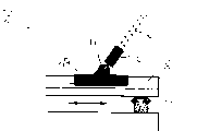
Fig. 9 is the fascinate sketch of equipment of the wind-force of sailing boat;
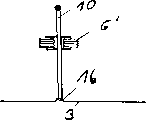
Figure 10 is the top view of hull;
Figure 11 is three kinds of modifications of thin-wall member, and the adjustment that wind is made;
Figure 12 is after considering wind-force, three kinds of embodiments of the adjustment of thin-wall member shape;
Figure 13 is the thin-wall member sketch that has assembled aerodynamics equipment;
Figure 14 is the derrick rig of installing for guy rope, provided suspension rod and has been installed in three figure on the hull;
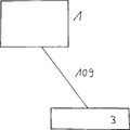
Figure 15 is the sketch of hull, and hull links together with thin-wall member by guy rope;
Figure 16 is a kind of embodiment of thin-wall member, comprising the air bag and the connecting branch of pressure gas;
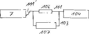
Figure 17 is gas air feed and a kind of embodiment structure of on-cycle sketch of invention;
Figure 18 is the second kind of gas air feed and the circulation embodiment of invention;
Figure 19 is the third gas air feed and the circulation embodiment of invention;
Figure 20 is the gas air feed and the circulation embodiment with two gas storage tanks of invention.
Two kinds of possible thin-wall member embodiment that in Fig. 1 and 2 are, according to the present invention, thin-wall member can adopt the shape of sail and kite respectively.
According to embodiment illustrated in fig. 1; thin-wall member (1) is connected on the hull that does not show among the figure (3) by four guy ropes (2); the length of four guy ropes (2) can be regulated separately, makes thin-wall member move to various position, regulates according to needed sense of motion and wind direction.
In such an embodiment, thin-wall member (1) is made by flexible material, such as being sir-tight film and textile material at least.Thin-wall member (1) is made bilayer at least, seals from the limit then to constitute an air bag (7), is full of helium inside.As long as considered the volume of air bag, the weight of thin-wall member (1) and the weight of guy rope, just can put on the air to air bag (7), so just can produce a lift, this lift is bigger than corresponding gravity, so thin-wall member will float over the scope of guy rope (2) length permission with in the interior atmosphere
The thin-wall member here (1) has shown corresponding profile and cross-sectional geometry respectively approx, and except its static lift, the geometric configuration that this with traditional aircraft wing is the same can produce a dynamic lift under the situation of air flows.By the length of four guy ropes of abundant adjusting (2), just can in wind, adjust the position to thin-wall member, can on a very big useful effect surface, obtain a huge air resistance, its direction is opposite with the direction of wind.
But just as what illustrate among the present invention, the guy rope of use (2) can be more than four, can be more favourable when the face area of thin-wall member is very big.
Thin-wall member embodiment (1) among Fig. 2 is similar to traditional kite, it is to be directly connected on the hull (3) that does not show among the figure by a guy rope, guy rope (2) begins to connect from hitch (20), there are three lines to be connected respectively to from hitch on the summit of thin-wall member (1) of kite shape; thin-wall member is made up of a framed structure (12), and this framework is preferably made by the material of light firm.Under the sort of situation, can use carbonfiber reinforced plastics tubulose or shaft-like, this material can make the textiles film stable and keep its shape.
The length adjustment of guy rope or many guy ropes (2) can be finished in various manners, in the explanation of another one figure this adjustment mode has been done good explanation.
Fig. 3 is the top view sketch of hull (3), has shown four guy ropes (2) on the figure, and the effective length of every guy rope between hull (3) and thin-wall member (1) can be adjusted by equipment (5) separately, and thin-wall member (1) does not show in this figure.From the illustration of Fig. 3,3a and 3b, can derive according to corresponding explanation draws several modes that guy rope changes.
Equipment (5) is exactly the pulley that is fixed on the common shape on the hull, and each guy rope can be wrapped in respectively on this pulley, also can unclamp from above.Four guy ropes are drawn towards a deflection pulley (6 ') from these pulleys (5), what this deflection pulley (6 ') adopted is so-called four assembly pulleys or two sister blocks, these four guy ropes are introduced to a deflection equipment (4) by four deflection pulleys (6) then, this deflection equipment (4) has just been represented the point of action of application force on hull (3) on the guy rope (2), guy rope is guided thin-wall member (1) into by this deflection equipment at last, and thin-wall member does not show in this figure.
In this case superincumbent, because the winding of pulley (5) or unclamp and will cause every guy rope (2) to shorten or elongated causes point of action (4) and thin-wall member (1) to produce selectively and is offset.Also can cause the skew of point of action (4) and thin-wall member (1) as the variation of the sister block group 6 ' position of the skew pulley of guy rope (2).The explanation of Fig. 3 a and 3b has been arranged, should look at conversely also how this reaches.
It in Fig. 3 a the enlarged drawing of Fig. 3 X part.
Being partial to several arrows that drawn specially on the pulley system (6 '), represent to be partial to the possibility of pulley system to point of action (4) position influence of power.Can do parallel or vertical moving with respect to the longitudinal axis of hull (3), and the pitch circle diameter moves, shown in the double-head arrow among the figure.A rotating table (11) is installed just can be realized that the pitch circle diameter moves, S. A. around symmetric arrangement deforms, like this, deflection system (6 ') is exactly to be arranged on the rotating table (11) in the accentric mode, advances along circuit orbit in the process of this rotating table of rotation.
Be to utilize throw of lever and jib boom (10) in other a kind of variation pattern, throw of lever and jib boom (10) are separately fixed on the joint (16) of hull, and the deflection system (6 ') of two sister block compositions is fixed on the jib boom (10).The upper end of jib boom (10) is under hand or mechanical action, it is pivoted automatically, because the deflection of thin-wall member (1), the deflection point of guy rope (2) just can depart from according to the motion of jib boom (10), and the position of deflection point is mainly determined by deflection system (6 ').
Particularly in Fig. 3 a, can see the fixedly orifice ring that is positioned at hull (3) bottom, these fixedly orifice ring be used for fixing other four deflection pulleys (6), guy rope (2) further change of direction in the deflection pulley.
At Fig. 4, Fig. 4 a and Fig. 4 b is control convenience embodiment among the present invention, be used to control wind force driving device, here four guy ropes (2) have been reused, four guy ropes (2) all have been drawn towards thin-wall member (1), and are connecting with concrete thin-wall member equipment thin-wall member as shown in fig. 1.Each root guy rope (2) all passes through an independent deflection pulley (6) and is drawn towards equipment (5), and by this method, the length of guy rope (2) just can change.The shape of equipment (5) can adopt normally used capstan winch on three-master and the sailing boat shown in Fig. 4 b, also can be made of free wheel and drg.In addition, can also add a crank in this equipment twines and unclamps guy rope.
By deflection system such as pulley system, according to sea language is four assembly pulleys, guy rope can change to the point of action (4) of the power that hull (3) applies, consider the required sense of motion and the direction of wind, by changing the length of four guy ropes (2), the position of application force is changed.
Y partial enlarged drawing among Fig. 4 a is clear and definite is fixed on the orifice ring (13) of hull (3) bottom, and these orifice rings are used for fixing deflection pulley (6).
Among the embodiment among Fig. 5, Fig. 5 a and Fig. 5 b, use guide rail (8) and (9) to change origin of force (4) with respect to the longitudinal axis of hull (3) and the position of lateral shaft.
The longitudinal axis balance of two longitudinal rails (9) and hull (3) is installed on two limits of hull.A horizontal guide rail (8) has been installed at two longitudinally in the guide rail (9), guide rail (8) can move on the whole length of hull if desired.
But, can only use cover (8) or (9) such guide rail.
In Fig. 5 a, can see the cutaway view of A-A, one or more guy rope (2) is drawn towards the deflection pulley (6) that is installed in the guide piece (14), and guide piece (14) is installed in the cross slide way (8), if do not use deflection pulley (6), above guy rope (2) just directly is drawn towards guide piece (14) and is connected.
In the Z of Fig. 5 b part enlarged drawing, can better observe, guide piece (14) guide rail (8) along the longitudinal moves reciprocatingly, guide rail (8) moves according to the indicated direction of double-head arrow on the track that shape is coincide, so, by moving of guide piece (14), origin of force (4) can be done the variation of orthogonal directions with respect to the longitudinal axis of hull, if cross slide way (8) along the longitudinal the direction of guide rail (9) install, can obtain the various change locations of origin of force (4).
Equipment among Fig. 6 is used to change the equipment of guy rope (2) effective length between hull (3) and the thin-wall member (1), and thin-wall member among this figure (1) shows not that in the drawings used double lever (5) in this equipment, guy rope (2) is connected to two ends.So the parallel bars lever arm can center on S. A. (15) and bending, so according to the angle of double lever (5) around S. A. (15) bending, double lever (5) left side or right side bonded assembly guy rope can be distinguished elongated or shorten.Guy rope is drawn towards thin-wall member (1) by a deflection pulley (6), and each deflection pulley (6) can be used the sister block group instead here.Under this condition, the deflection pulley system can be represented the point of action (4) of power.
Among the embodiment of Fig. 7, Fig. 7 a and Fig. 7 b, jib boom (10) is used to change the position of the point of action (4) of application force on the guy rope, and jib boom (10) is connected on the hull (3) by joint (16).
Joint (16) preferably uses ball-joint to be connected and universal-joint with sleeve, utilizes joint (16), and jib boom (10) just can rotate to each different direction around axle.
Guy rope (2) is connected to jib boom (10) and goes up an end opposite with joint (16), and the length of jib boom (10) can exceed the extreme length of hull (3), therefore, by more suitable lever relationshhip, can further reduce tilting moment.
Shown in Fig. 7 a, jib boom (10) at least can one tethered system fix and align, preferably the tethered system with two bunt line forms fixes and align (this point is opposite with explanation), this equipment all is to name with sea language.
Be the partial enlarged drawing of W-W ' among Fig. 7 among Fig. 7 b, it has illustrated joint (16) and anchor fitting, has also had jib boom (10) to go up the arrangement of bonded assembly guy rope (2) on hull (3).
Embodiment in Fig. 8 and Fig. 8 a is used for changing the length of guy rope (2), and the method that changes single guy rope (2) has two kinds, and these two kinds of methods can be used separately, and use also can combine.
Therefore, two guy ropes (2) are wrapped in respectively on the pulley (5) as capstan winch, are conducted through a deflection pulley system then, and this system has four pulleys here and should be made up of two deflection pulleys (6) at least.
According to the top view among Fig. 8 as can be seen, two deflection pulleys (6) can one in front and one in back be installed at least.
Can very clearly find out from Fig. 8 a, be partial to operating of pulley (6), and connect together with the pedal (19) that is installed on the guide rail (18) in the fit closely mode of shape.When pedal (19) laterally along guide rail (18) when moving forward and backward, the effective length of corresponding guy rope (2) will shorten or prolong, guide rail (18) itself is mounted on the hull (3).
In Fig. 9, be a sailing boat that comprises hull, hull (3) has been equipped with leeboard (21) and traditional rudder.Connected four guy ropes (2) on hull (3), the other end of guy rope (2) is connected on the thin-wall member (1), and this thin-wall member is the sail that textiles is made.At the thin-wall member edge of this sail shape, around an air bag (7), this air bag (7) also can be made up of a lot of the ballonets that contain gas that separate.Utilize this air bag (7) to play a framework and stable effect for the thin-wall member (1) of flexibility.If the thin-wall member of rod and sufficient airbag design, its stability can also be strengthened greatly.
The length of guy rope can change in various form, changes such as a system that can use the front to describe.
It in Figure 10 the top view of hull (3), under the sort of situation, dash area can extend and exceed the whole width of hull (3), what this shaded area on the hull lateral shaft was represented is, in order to reduce the actuating speed that tilts and realize the best, the position that the point of action of power can be located by the guide rail (8) among Fig. 5 a and Fig. 5 b and (9).If used rotating table or jib boom (10), this regional shape is exactly circular.
The effect that the location of the point of action by power can reach has been mentioned in the comprehensive part of explanation.
Be the embodiment of amended thin-wall member in Figure 11, can identify the cross-sectional plane situation of each equipment here.Thin-wall member (1) is to build according to the shape of the wing of aircraft; what thin-wall member (1) can be represented in Figure 11 adjusts direction according to wind like that; utilize such equipment just can go up produce a lift that makes progress at thin-wall member (1) under wind action; this lift just can be used as the propulsive force of ship, demonstration among guy rope (2) figure here by guy rope (2).Utilize the various improvement of representing among Figure 11, under corresponding various wind flow situations, on the point of action of power, just can produce various propulsive forces.
If the modification shown in thin-wall member (1) Figure 11 that uses, except the Cd factor, so-called Ca coefficient (shape lift coefficient) has very important significance, and in this case, the Ca coefficient should be big, and the corresponding drag force factor should keep very little.
If influence 3D shape by section, position, air dynamic behaviour and corresponding application force all can be subjected to the influence of the Cd factor and Ca coefficient so.
In the navigation process of ship, the shape of thin-wall member also can be subjected to the influence of the internal pressure of air bag (7) variation.
Be other three embodiment of the thin-wall member (1) after the Adjusting Shape in Figure 12, this thin-wall member (1) can be adjusted by the length that changes each guy rope (2), by this method, can obtain bigger wind-force.
Therefore, the shape of speaking of above can be used for little wind under medium wind condition, keeps its aerodynamics relation by this shape, to obtain maximum propulsive force.
By setting the shape of thin-wall member (1), its propulsive force can reduce under very big wind effect, under very large wind speed effect, when taking place as blast; the shape of thin-wall member (1) change just as the most following among Figure 12 and that figure the time; will cause propulsive force to be reduced to zero, corresponding, just very low at the tension force of the point of action of power.At other unsafe conditions, can also adjust this modification, as having mentioned at least one sensor string is installed in the leader part.
Figure 13 is the sketch of thin-wall member (1), four aerodynamics pivo table member (32) have been installed on this thin-wall member (1), they can pivot separately or rotation together, use them in order to make in the selectivity motion of equipment on horizontal or vertical direction, they can regulate definite angle of rotation according to the surface of thin-wall member (1), and they can work as the aileron and the horizontal stabilizer of aircraft like this.At the rope of the last suitable length of these equipment (32), can adjust the angle that facings the wind.If these equipment (32) are installed on the thin-wall member (1) in the mode on plane, they will be ineffective.
Utilize these aerodynamics equipment (32), can change the Cd/Ca ratio, with the shape generation propulsive force of various needs.
In Figure 14, the function of derrick rig (35) and effect will describe by graphic form.Only be installed in the bar-shaped derrick rig (35) on the hull among the figure, a guy rope (2) has been played effect and effect.When thin-wall member was floating in wind, guy rope (2) represented that with solid line ship course line is as required moved, and that is to say that ship direction as required moves.If thin-wall member (1) has taken place to float, its corresponding guy rope (2) will be moved, will run into derrick rig (35) then, under the effect of derrick rig, this floating will be restricted, do not needing under manual operation or other the situation of operating the rudder, this floating just can make the motion of thin-wall member (1) switched in opposite direction.
Certainly, can many this derrick rigs (35) be installed, not show so many derrick rigs (35) among the figure for guy rope.These derrick rigs (35) also can partner, and are used for a guy rope (2) then, and each is used for limiting floating on thin-wall member (1) both direction to derrick rig (35).
But the derrick rig (35) that is used for guy rope can be made a bundle and use, and this has mentioned in the leader part.
In Figure 15 with a sketch of very simply representing a wind driven vessel (3), ship (3) is connected on the thin-wall member (1) of shape as a kite by at least one guy rope (100), like this, act on the propulsive force that the top wind-force of thin-wall member (1) just can be used as hull (3).
What represent in Figure 16 is a thin-wall member (1) and an air bag (7), has comprised a connecting branch (108) in air bag (7), and the same conduit of connecting branch (108) (111) joins.By this conduit (111), just can in air bag, charge into helium.The air bag (7) that charges into gas has just constituted an element that produces raising force, and its lift is enough to the gravity of negative function on thin-wall member.
Connecting branch (108) can be designed to traditional quick throttle gate, for example, after air bag (7) inflation finishes, connecting branch (108) but at high speed locking, first conduit (111) that does not show among the figure also can unclamp from connecting branch (108) once more.When only gas will carry out reflux cycle in air bag (7), this connection can be communicated with once more.
Be the sketch of an equipment in Figure 17, represented to open when valve (102) how pressure gas pours into from pressure gas holding vessel (104) in the air bag (7) of (1) of thin-wall member, valve (102) is installed on first conduit (111).Under the sort of situation, valve (105) is installed on second conduit (103), and conduit (103) is installed in valve (102) next door with the form of bypass, and at this moment, valve (105) is closed.
For gas is back to the compression gas accumulator (104) from air bag (7), valve (102) will be closed, and the valve (105) that is installed on second conduit (103) will be opened, the power that an expansion is preferably arranged on air bag (7) here is back in the pressure gas holding vessel (104) from air bag (7) to help gas.
Be another embodiment of gas supply and refluxing unit in Figure 18, gas pours into the air bag (107) and oppositely pour into pressure gas holder (104) from air bag (107) from pressure gas holder (104).Here, two conduits (111) are connected with air bag (7) with pressure gas holding vessel (104) respectively in parallel to each other with (103).In the pressure gas holding vessel in (104) with the gas that exists of mode of compression, enter into air bag (7) can open in valve (102) after, and temporarily be stored in the there and be thin-wall member (1) generation lift.
When air bag (7) will discharge gas, valve (102) closed conduit (111) is broken from connection, simultaneously compressor (107) is opened, the suction side of this compressor (107) links together with air bag, just the gas in the air bag (7) can be pumped in the pressure gas holding vessel (104).
Embodiment among Figure 19 improves according to the embodiment among Figure 18, in Figure 19, conduit (103) forms a bypass around valve (102), but, explanation just as the leader part, valve (102) and compressor (107) and conduit (111) and (103) can exchange, but do not provide the figure after the exchange.
Illustrate also that in Figure 19 first conduit (111) has at least a part (111 ') should adopt flexible pipe.
Be a gas supply and backflow embodiment in Figure 20, this embodiment is furnished with two pressure gas holding vessels (104) and (114).
Under the sort of situation, the built-in pressure ratio of pressure gas holding vessel (104) is higher, and after the valve (102) on first conduit (111) was opened, air bag just can be inflated.
Valve-off (102) and opening installation are at the second supravasal valve (105), the gas that is compressed fully in air bag (7) just can flow in second pressure gas holding vessel (114), and temporarily be stored in the there with lower pressure, the internal volume of pressure gas holding vessel (114) is bigger than the internal volume of compression gas storage tank (104).Temporarily being stored in the middle lower gas of pressure of pressure gas (104) has just entered in the pressure gas holder (104), just gas is compressed and replenish opening the back suitable time of compressor (107), the suction side of this compressor (107) links to each other with pressure gas holding vessel (104), and its air-supply side is connected with pressure gas holding vessel (104).
Claims (40)
1. wind driven boat, thin-wall member on it is at least by being that a guy rope that is connected on the hull is controlled, and described guy rope is to be connected on the thin-wall member (1) with three point of connection spaced apart from each other at least, it is characterized in that the point of action (4) of the power on the guy rope on hull (3) can change according to the sense of motion of wind direction and ship.
2. the ship of claim 1 is characterized in that described thin-wall member (1) made by flexible material.
3. claim 1 or 2 ship is characterized in that at the air bag (7) that has a pressure gas on the described thin-wall member (1) at least and/or have at least the air bag of a pressure gas to be connected on the thin-wall member (1).
4. one of any ship in the claim 1 to 3 is characterized in that described pressure gas air bag (7) has been charged into the pressure gas lower than density of air.
5. one of any ship in the claim 1 to 3 is characterized in that on the pressure gas air bag pore being arranged, and utilizes the dynamic pressure of wind to inflate.
6. one of any ship in the claim 1 to 5 is characterized in that controlling guy rope with a set of equipment (5), is adjusted in the length of described guy rope between described thin-wall member (1) and described hull (3) on the described hull.
7. the ship of claim 6 is characterized in that every guy rope (2) all controlled by the described equipment (5) on the described hull (3) respectively, to regulate the length (2) of guy rope.
8. the ship of claim 1 is characterized in that the point of action (4) of power can change along the guide rail (8,9) that is fixed on the hull (3).
9. the ship of claim 1, the point of action (4) that it is characterized in that power is that accentric is distributed on the rotating table (11) that is fixed on the hull (3).
10. the ship of claim 1 is characterized in that the point of action (4) of power all is distributed on the jib boom (10) that can pivot, and the spar that retreads (10) then is connected on the described hull (3).
11. one of any ship in the claim 1 to 10, the point of action (4) that it is characterized in that power can change with respect to the side tension force point of action of hull (3).
12. one of any ship in the claim 1 to 11 is characterized in that the point of action (4) of power can be made parallel change and/or quadrature changes with respect to the longitudinal axis of ship.
13. one of any ship in the claim 1 to 12 is characterized in that the length of described guy rope (2) can change separately.
14. one of any ship in the claim 1 to 13 is characterized in that the described guy rope of each root (2) all is wrapped on the independent pulley (6).
15. one of any ship in the claim 1 to 14 is characterized in that described guy rope (2) will pass through a deflection pulley (6) at least.
16. one of any ship in the claim 1 to 15 is characterized in that described deflection pulley (6) is movably.
17. one of any ship in the claim 1 to 16 is characterized in that the one side of described three guy ropes (2) is fixed on the hull (3), another side is that leg-of-mutton three points are connected on the described thin-wall member (1) with span.
18. one of any ship in the claim 1 to 16 is characterized in that the one side of described four guy ropes (2) is fixed on the hull (3), another side is that four points of rectangle are connected on the described thin-wall member (1) with the span.
19. one of any ship in the claim 1 to 18 is characterized in that described pressure gas air bag (7) is located at the edge in described thin-wall member (1).
20. one of any ship in the claim 1 to 19 is characterized in that the weight of the lift of described pressure gas air bag (7) more than or equal to thin-walled structure (1).
21. one of any ship in the claim 1 to 20 is characterized in that having at least a hydraulic power equipment (31) to be installed on the described hull (3).
22. one of any ship in the claim 1 to 21 is characterized in that described hydraulic power equipment (31) can pivot.
23. one of any ship in the claim 1 to 22 is characterized in that the angle of pivoting of described hydraulic power equipment (31) can be regulated according to the speed of ship and/or the tension force of described thin-wall member (1).
24. one of any ship in the claim 1 to 23, it is characterized in that at described thin-wall member (1) but on an aerodynamic force be installed at least driven the equipment (32) that pivots.
25. one of any ship in the claim 1 to 24, the leeboard that it is characterized in that being connected on the hull (3) can be around the longitudinal axis rotation.
26. one of any ship in the claim 1 to 25 is characterized in that having at least the sense line of velamen guiding hull (3) to be connected on the described thin-wall member (1).
27. one of any ship in the claim 1 to 26 is characterized in that on described guy rope (2) overload protection device being installed.
28. one of any ship in the claim 1 to 27 is characterized in that in the outer rim of thin-wall member (1) gas-flow separation unit being installed.
29. one of any ship in the claim 1 to 28 is characterized in that having installed guy rope suspension rod equipment (35) on hull (3).
30. one of any ship in the claim 1 to 29, it is characterized in that having at least a described pressure gas air bag (7) to be connected at least one pressure gas holding vessel (104), and described pressure gas air bag (7) can be by described gas storage tank (104) inflation by one first conduit (111) and a valve (102).
31. the described ship of claim 30, it is characterized in that in order to make gas be back to one or second pressure gas holding vessel (104 from described pressure gas air bag (7), 114) in, second conduit (103) has been installed, and this conduit (103) is connected to described pressure gas air bag (7) or has been connected to described first conduit (111).
32. claim 30 or 31 described ships is characterized in that the part of at least the first conduit (111) is a flexible structure.
33. one of any ship in the claim 30 to 32 is characterized in that compressor (107) and second conduit (103) linearly arrange.
34. one of any ship in the claim 20 to 33, it is characterized in that the pressure of pressure gas described in described first pressure gas holder (104), this pressure be greater than or equal to described pressure gas air bag 7) internal pressure.
35. one of any ship in the claim 30 to 34, the suction side that it is characterized in that described compressor (107) has been connected to described pressure gas air bag (7), and the air-supply side has been connected on the described pressure gas holding vessel (104,114) that is positioned on described second conduit (103).
36. one of any ship in the claim 30 to 35 is characterized in that described second conduit (103) and described compressor (107) have been connected to described first conduit (111) along the form of described valve (102) bypass.
37. one of any ship in the claim 30 to 35, it is characterized in that described first conduit (111) around described compressor (107) by and as its bypass, on first conduit (111), described two way valve has been installed.
38. one of any ship in the claim 30 to 37 is characterized in that described pressure gas air bag (7) and described pressure gas holder (104) have been charged into the low gas of density ratio air.
39. one of any ship in the claim 30 to 38 is characterized in that a described pressure gas holding vessel (104,114) to be installed on the ship at least.
40. one of any ship in the claim 30 to 38 is characterized in that on described pressure gas air bag, for described first conduit (111) has been installed at least one lockable connecting branch (108).
Applications Claiming Priority (4)
| Application Number | Priority Date | Filing Date | Title |
|---|---|---|---|
| DE10027691 | 2000-05-31 | ||
| DE10027691.1 | 2000-05-31 | ||
| DE10065630 | 2000-12-21 | ||
| DE10065630.7 | 2000-12-21 |
Publications (1)
| Publication Number | Publication Date |
|---|---|
| CN1431963A true CN1431963A (en) | 2003-07-23 |
Family
ID=26005959
Family Applications (1)
| Application Number | Title | Priority Date | Filing Date |
|---|---|---|---|
| CN01810441A Pending CN1431963A (en) | 2000-05-31 | 2001-05-31 | Wind driven boat |
Country Status (12)
| Country | Link |
|---|---|
| US (1) | US20030140835A1 (en) |
| EP (1) | EP1409339B8 (en) |
| JP (1) | JP2003534982A (en) |
| KR (1) | KR100833146B1 (en) |
| CN (1) | CN1431963A (en) |
| AT (1) | ATE399709T1 (en) |
| AU (1) | AU2001267326A1 (en) |
| DE (2) | DE10192193D2 (en) |
| DK (1) | DK1409339T3 (en) |
| NO (1) | NO335589B1 (en) |
| PL (1) | PL200417B1 (en) |
| WO (1) | WO2001092102A1 (en) |
Cited By (2)
| Publication number | Priority date | Publication date | Assignee | Title |
|---|---|---|---|---|
| CN1968850B (en) * | 2004-04-19 | 2010-04-07 | 天帆两合公司 | Placement system for a flying kite-type wind-attacked element in a wind-powered watercraft |
| CN1968848B (en) * | 2004-04-19 | 2010-06-16 | 天帆两合公司 | Watercraft comprising a free-flying kite-type wind-attacked element as a wind-powered drive unit |
Families Citing this family (14)
| Publication number | Priority date | Publication date | Assignee | Title |
|---|---|---|---|---|
| WO2002018202A1 (en) * | 2000-08-31 | 2002-03-07 | Edwin Lundgren | Control device for a steering kite on a boat |
| WO2003097448A1 (en) | 2002-05-16 | 2003-11-27 | Stephan Wrage | Wind-propelled watercraft |
| US7093803B2 (en) * | 2003-12-16 | 2006-08-22 | Culp David A | Apparatus and method for aerodynamic wing |
| DE202004013841U1 (en) * | 2004-09-06 | 2006-01-19 | Skysails Gmbh & Co. Kg | Watercraft with a kite-like element |
| US7866271B2 (en) * | 2004-04-19 | 2011-01-11 | Skysails Gmbh & Co. Kg | Placement system for a flying kite-type wind-attacked element in a wind-powered watercraft |
| DE102004018838A1 (en) | 2004-04-19 | 2005-11-03 | Skysails Gmbh | Positioning device for a free-flying kite-like wind attack element in a watercraft with wind propulsion |
| DE202004013840U1 (en) | 2004-09-06 | 2006-01-19 | Skysails Gmbh & Co. Kg | Watercraft with a kite-like element |
| JP2010500221A (en) * | 2006-08-15 | 2010-01-07 | スカイセイルズ・ゲゼルシャフト・ミット・ベシュレンクテル・ハフツング・ウント・コムパニー・コマンディットゲゼルシャフト | Launch / recovery mechanism for aerodynamic profile elements and aerodynamic profile elements |
| ATE536305T1 (en) | 2006-09-14 | 2011-12-15 | Skysails Gmbh | STEERING UNIT FOR FREE-FLYING, RESTRICTED WING ELEMENT |
| US7775483B2 (en) * | 2008-12-03 | 2010-08-17 | Gaylord G Olson | Launch and recovery system for tethered airborne elements |
| AU2011286106A1 (en) * | 2010-08-05 | 2013-02-21 | Crosswind Power Systems Inc. | Method and system for harnessing wind energy using a tethered airfoil |
| EP2844552B1 (en) | 2012-05-03 | 2017-03-08 | Skysails GmbH | Aerodynamic wind energy conversion device and method for controlling such a device |
| ITTO20130481A1 (en) * | 2013-06-12 | 2013-09-11 | Kite Gen Res Srl | WING WITH BIMODAL OPERATION. |
| DE102015111224A1 (en) | 2015-07-10 | 2017-01-12 | Skysails Gmbh | Starting and recovery device for a tethered wind power element |
Family Cites Families (17)
| Publication number | Priority date | Publication date | Assignee | Title |
|---|---|---|---|---|
| US3720180A (en) * | 1970-11-27 | 1973-03-13 | P Stangeland | Raffe sail for boats |
| US3839978A (en) * | 1973-07-12 | 1974-10-08 | W Hendrickson | Yacht kit |
| US4296704A (en) * | 1979-05-07 | 1981-10-27 | Bridge John G | Anti-gravity spinnaker |
| JPS58143794U (en) * | 1982-03-23 | 1983-09-28 | 日立造船株式会社 | Marine wind propulsion system |
| JPS58206490A (en) * | 1982-05-25 | 1983-12-01 | ザ・ブリテイツシユ・ピトロ−リアム・コンパニ−・ピ−・エル・シ− | Lifting sail and its control |
| US4497272A (en) * | 1982-06-01 | 1985-02-05 | Veazey Sidney E | Mastless sails |
| FR2569159A1 (en) * | 1984-08-17 | 1986-02-21 | Tomczak Zdzislaw | Lighter-than-air structure for aeolian traction |
| DE3518131A1 (en) * | 1985-05-21 | 1986-11-27 | Dieko 8720 Schweinfurt Bruins | Vessel propulsion with suspension sail |
| JPS621691A (en) * | 1985-06-26 | 1987-01-07 | Yokoyama Zosen Sekkei Jimusho:Kk | Automatic steering method for shipping and device thereof |
| US4930729A (en) * | 1986-05-22 | 1990-06-05 | Rolls-Royce Plc | Control of fluid flow |
| US4947775A (en) * | 1988-05-12 | 1990-08-14 | Bamford Robert M | Water air interface vehicle |
| FR2639605B1 (en) * | 1988-11-28 | 1991-03-29 | Durand Gilles | FLEXIBLE FLYING WING WITH TRACTOR CABLES, PARTICULARLY FOR PULLING A BOAT |
| US4969411A (en) * | 1989-09-14 | 1990-11-13 | Smernoff Gerald N | Track-to-track adaptor system for genoa lead car adjustment |
| US5095837A (en) * | 1990-09-28 | 1992-03-17 | Baird Lincoln F | Ram-air inflatable beam for use with a spinnaker |
| FR2690129B1 (en) * | 1992-04-21 | 1998-07-03 | Louis Rivieccio | RIGGING FOR BOAT COMPRISING A VEHICLE NOT SUPPORTED BY A MAST. |
| WO1994029168A1 (en) * | 1992-04-21 | 1994-12-22 | Louis Rivieccio | Rigging comprising a sail with no mast and hydropter fitted with such rigging |
| US5642683A (en) * | 1996-04-26 | 1997-07-01 | Bedford; Norman | Parachute-type sail for boats |
-
2001
- 2001-05-31 WO PCT/DE2001/002124 patent/WO2001092102A1/en active IP Right Grant
- 2001-05-31 AT AT01944972T patent/ATE399709T1/en not_active IP Right Cessation
- 2001-05-31 US US10/296,649 patent/US20030140835A1/en not_active Abandoned
- 2001-05-31 JP JP2001588085A patent/JP2003534982A/en active Pending
- 2001-05-31 PL PL358964A patent/PL200417B1/en unknown
- 2001-05-31 DE DE10192193T patent/DE10192193D2/en not_active Expired - Fee Related
- 2001-05-31 AU AU2001267326A patent/AU2001267326A1/en not_active Abandoned
- 2001-05-31 KR KR1020027016071A patent/KR100833146B1/en not_active IP Right Cessation
- 2001-05-31 EP EP01944972A patent/EP1409339B8/en not_active Expired - Lifetime
- 2001-05-31 CN CN01810441A patent/CN1431963A/en active Pending
- 2001-05-31 DK DK01944972T patent/DK1409339T3/en active
- 2001-05-31 DE DE50114078T patent/DE50114078D1/en not_active Expired - Lifetime
-
2002
- 2002-11-29 NO NO20025746A patent/NO335589B1/en not_active IP Right Cessation
Cited By (2)
| Publication number | Priority date | Publication date | Assignee | Title |
|---|---|---|---|---|
| CN1968850B (en) * | 2004-04-19 | 2010-04-07 | 天帆两合公司 | Placement system for a flying kite-type wind-attacked element in a wind-powered watercraft |
| CN1968848B (en) * | 2004-04-19 | 2010-06-16 | 天帆两合公司 | Watercraft comprising a free-flying kite-type wind-attacked element as a wind-powered drive unit |
Also Published As
| Publication number | Publication date |
|---|---|
| EP1409339A1 (en) | 2004-04-21 |
| DE50114078D1 (en) | 2008-08-14 |
| PL200417B1 (en) | 2009-01-30 |
| EP1409339B8 (en) | 2008-08-27 |
| NO20025746D0 (en) | 2002-11-29 |
| NO335589B1 (en) | 2015-01-05 |
| ATE399709T1 (en) | 2008-07-15 |
| AU2001267326A1 (en) | 2001-12-11 |
| KR100833146B1 (en) | 2008-05-28 |
| DE10192193D2 (en) | 2003-04-24 |
| NO20025746L (en) | 2003-01-29 |
| KR20030025232A (en) | 2003-03-28 |
| JP2003534982A (en) | 2003-11-25 |
| WO2001092102A1 (en) | 2001-12-06 |
| EP1409339B1 (en) | 2008-07-02 |
| DK1409339T3 (en) | 2008-10-27 |
| US20030140835A1 (en) | 2003-07-31 |
| PL358964A1 (en) | 2004-08-23 |
Similar Documents
| Publication | Publication Date | Title |
|---|---|---|
| CN1431963A (en) | Wind driven boat | |
| JP5139571B2 (en) | Ship vibration reduction and levitation equipment | |
| CN1123482C (en) | High speed hybrid marine vessel | |
| JP2598252B2 (en) | Catamaran boat | |
| EP0241472A1 (en) | Fast self righting catamaran | |
| CN101056794A (en) | Improved convertible vessel | |
| US20120024211A1 (en) | Articulated marine vehicle | |
| AU656247B2 (en) | Multi-hull vessel | |
| CN110155244A (en) | A kind of wave energy aircraft that captain can be changed | |
| CN112761128A (en) | Offshore wind power double-body installation platform and cylindrical foundation installation method | |
| CN1142803A (en) | Boat | |
| US4592298A (en) | Propulsion system for sailing crafts and ships | |
| CN102556313B (en) | Adjustable drive system for surface paddle and boat | |
| CN1453184A (en) | Water floated platform and its storm load reducing method | |
| US20030121462A1 (en) | Sailing craft | |
| CN1034115C (en) | Multiple hull air ride boat | |
| TW202106973A (en) | Floating structure installation system and floating structure installation method | |
| US11242115B1 (en) | Boat stabilizer | |
| CN214573828U (en) | Marine wind power binary mounting platform | |
| US8156879B2 (en) | Sailing craft comprising a tilting rigid sail system | |
| US20090151614A1 (en) | Sailing craft comprising a tilting rigid sail system | |
| US20220388612A1 (en) | Boat stabilizer with controllable parasail | |
| JP4682201B2 (en) | Means of transport | |
| CN111661254B (en) | Convenient liquefied natural gas carrier | |
| CN101723055B (en) | Ship structure and operating method thereof |
Legal Events
| Date | Code | Title | Description |
|---|---|---|---|
| C06 | Publication | ||
| PB01 | Publication | ||
| C10 | Entry into substantive examination | ||
| SE01 | Entry into force of request for substantive examination | ||
| C02 | Deemed withdrawal of patent application after publication (patent law 2001) | ||
| WD01 | Invention patent application deemed withdrawn after publication |