CN1344109A - Ref reproduction equipment - Google Patents
Ref reproduction equipment Download PDFInfo
- Publication number
- CN1344109A CN1344109A CN01119944.XA CN01119944A CN1344109A CN 1344109 A CN1344109 A CN 1344109A CN 01119944 A CN01119944 A CN 01119944A CN 1344109 A CN1344109 A CN 1344109A
- Authority
- CN
- China
- Prior art keywords
- ratio
- width
- height
- monitor
- progressive
- Prior art date
- Legal status (The legal status is an assumption and is not a legal conclusion. Google has not performed a legal analysis and makes no representation as to the accuracy of the status listed.)
- Pending
Links
Images


Classifications
-
- H—ELECTRICITY
- H04—ELECTRIC COMMUNICATION TECHNIQUE
- H04N—PICTORIAL COMMUNICATION, e.g. TELEVISION
- H04N7/00—Television systems
- H04N7/01—Conversion of standards, e.g. involving analogue television standards or digital television standards processed at pixel level
- H04N7/0117—Conversion of standards, e.g. involving analogue television standards or digital television standards processed at pixel level involving conversion of the spatial resolution of the incoming video signal
- H04N7/012—Conversion between an interlaced and a progressive signal
-
- H—ELECTRICITY
- H04—ELECTRIC COMMUNICATION TECHNIQUE
- H04N—PICTORIAL COMMUNICATION, e.g. TELEVISION
- H04N7/00—Television systems
- H04N7/01—Conversion of standards, e.g. involving analogue television standards or digital television standards processed at pixel level
- H04N7/0117—Conversion of standards, e.g. involving analogue television standards or digital television standards processed at pixel level involving conversion of the spatial resolution of the incoming video signal
- H04N7/0122—Conversion of standards, e.g. involving analogue television standards or digital television standards processed at pixel level involving conversion of the spatial resolution of the incoming video signal the input and the output signals having different aspect ratios
-
- H—ELECTRICITY
- H04—ELECTRIC COMMUNICATION TECHNIQUE
- H04N—PICTORIAL COMMUNICATION, e.g. TELEVISION
- H04N9/00—Details of colour television systems
- H04N9/79—Processing of colour television signals in connection with recording
- H04N9/7921—Processing of colour television signals in connection with recording for more than one processing mode
-
- H—ELECTRICITY
- H04—ELECTRIC COMMUNICATION TECHNIQUE
- H04N—PICTORIAL COMMUNICATION, e.g. TELEVISION
- H04N21/00—Selective content distribution, e.g. interactive television or video on demand [VOD]
- H04N21/40—Client devices specifically adapted for the reception of or interaction with content, e.g. set-top-box [STB]; Operations thereof
- H04N21/47—End-user applications
- H04N21/488—Data services, e.g. news ticker
- H04N21/4884—Data services, e.g. news ticker for displaying subtitles
-
- H—ELECTRICITY
- H04—ELECTRIC COMMUNICATION TECHNIQUE
- H04N—PICTORIAL COMMUNICATION, e.g. TELEVISION
- H04N5/00—Details of television systems
- H04N5/76—Television signal recording
- H04N5/84—Television signal recording using optical recording
- H04N5/85—Television signal recording using optical recording on discs or drums
Abstract
A video signal reproduction apparatus for receiving an information signal including a video signal and a determination signal indicating a type of the video signal, and reproducing the video signal included in the information signal. The apparatus comprises a conversion section for converting the video signal to a progressive scan video signal, and an aspect ratio conversion section for converting an aspect ratio of the progressive scan video signal output from the conversion section and outputting the converted progressive scan video signal to a progressive scan video monitor. The aspect ratio conversion section converts the aspect ratio of the progressive scan video signal based on the determination signal indicating the type of the video signal and monitor information indicating a type of the progressive scan video monitor.
Description
The present invention relates to a kind of Ref reproduction equipment, be used for reproducing the vision signal that writes down at band medium, dish medium etc., or broadcasting, terrestrial broadcastings etc. via satellite carry the vision signal of the various pictorial information of film data for example or video data as progressive-scan video signal.
Usually, the vision signal of record in band medium, dish medium etc., or the vision signal of transmissions such as broadcasting, terrestrial broadcasting via satellite is output so that video receiver can reproduce these vision signals as interleaved vision signal by Ref reproduction equipment usually.Recently, the Ref reproduction equipment of interlaced video signal to progressive-scan video signal appears being used to change, as the monitor and the projecting apparatus of the many scannings of compatibility, or computer monitor, use more and more widely.
The ratio of the perpendicular size of horizontal size that terminology used here " the ratio of width to height " is meant the perpendicular magnitude proportion of horizontal size of an image and shows the monitor screen of an image.
Figure 12 is the structured flowchart that is used for being reproduced in the conventional Ref reproduction equipment 1200 of the information signal that the disc-type medium writes down.Among Figure 12, reference number 1 indicating panel records information signal in advance with coding and the modulation signal form that is applicable to record (or reproduction).This information signal comprise a vision signal and one the indication this vision signal type calibrate will really.
This Ref reproduction equipment 1200 comprises: pick-up head 2 is used for converting the information signal of record on the dish 1 to the signal of telecommunication; Disc spins device 3 is used for to be suitable for coiling 1 rotating speed rotating disk 1; Data is determined circuit 5, is used for determining the type of a vision signal according to the sign of should determining that this information signal comprises; Transducer 101 is used for the vision signal that the electrical signal conversion by pick-up head 2 conversion is become interleaved vision signal and lines by line scan; Encoder 7 is used for this interleaved vision signal is converted to the ntsc video form and gives an interlaced scanning video monitor 103 by horizontally interlaced image lead-out terminal 8 these results of output; With aberration transducer 10, be used for this progressive-scan video signal from transducer 101 outputs is converted to an analog color difference signal and by a progressive scanned video lead-out terminal 11 this result exported to a progressive scanned video monitor 104.
This transducer 101 comprises: interlaced video signal reproducing circuit 4 is used for the signal of telecommunication from pick-up head 2 outputs is carried out the demodulation sign indicating number so that the result is exported as interlaced video signal; Interlacing scan aspect ratio conversion circuit 6 is used to change the ratio of width to height of this interlaced video signal and exports this result; Interlacing scan the ratio of width to height specified portions 13 is made the ratio of width to height that is used for specifying interlaced scanning video monitor 103 by the user; Interlacing scan control circuit 12 is used for according to being determined video signal type that circuit 5 is determined by data and by the type of the interlaced scanning video monitor 103 of interlacing scan specified portions 13 appointments, control interlacing scan aspect ratio conversion circuit 6; With progressive-scan video signal change-over circuit 9, the interlaced video signal that is used for having the ratio of width to height of conversion converts progressive-scan video signal to and exports the result.
The operation of the Ref reproduction equipment of the routine that constitutes is like this described with reference to Figure 13 to 21 below.
Figure 13 is the summary schematic diagram of representing from the structure of coiling 1 vision signal of reproducing.In interlaced video signal, produced visual one in 1/60 second.Two constitute a frame image.The vertical number of picture elements of each in two is 240.Two scan line is an alternate configurations.In other words, one pixel is configured between in vertical direction other the two adjacent pixels.In progressive-scan video signal, produced a frame of image in 1/60 second, the number of picture elements of vertical direction is 480.Two kinds of signals all have 1/60 second vertical frequency.The horizontal scanning line number of progressive-scan video signal is that the horizontal scanning line of interlaced video signal is counted twice.The horizontal frequency of interlaced video signal is about 15.75KHz, and the horizontal frequency of progressive-scan video signal is its twice, promptly about 31.5KHz.
Figure 14 A is the summary schematic diagram from the structure of coiling 1 vision signal of reproducing.From coiling 1 vision signal of reproducing three kinds of forms are arranged.The representative of the vision signal of first kind of form has a kind of image of filling up 4: 3 full frame information (below be referred to as 4: 3 full figures resemble 301).The representative of the vision signal of second kind of form is at one 16: 9 images of the centre of 4: 3 screens, and the upper and lower hides hypographous a kind of image (below be referred to as 4: 3 mailbox (letterbox) images 302).The representative of the vision signal of the third form has a kind of image of filling up 16: 9 full frame information (below be referred to as 16: 9 full figures resemble 303).
Figure 14 B shows the ratio of width to height of interlaced scanning video monitor 103.As shown in Figure 14B, two kinds of monitors that are used for interlaced scanning video monitor 103 are arranged, a kind of have the ratio of width to height of 4: 3 and another kind has the ratio of width to height of 16: 9.
Figure 14 C shows the ratio of width to height of progressive scanned video monitor 104.Shown in Figure 14 C, the monitor of two kinds of monitors 104 that are used to line by line scan is arranged, a kind of have the ratio of width to height of 4: 3 and another kind has the ratio of width to height of 16: 9.
Interlaced video signal reproducing circuit 4 reads the signal that dish 1 writes down from the output of pick-up head 2, reproduces this interlaced video signal, and the result is exported to interlacing scan aspect ratio conversion circuit 6.Data determines that circuit 5 reads definite sign from the output of pick-up head 2, determines the type of this vision signal, and this result is exported to interlacing scan control circuit 12 as definite signal.
The user uses the type (the ratio of width to height) of the interlaced scanning video monitor 103 of interlacing scan the ratio of width to height specified portions 13 designated user desired output interlaced video signals.Interlacing control circuit 12 is determined definite signal of circuit 5 output and is controlled interlacing scan aspect ratio conversion circuit 6 by the type (the ratio of width to height) of the interlaced scanning video monitor 103 of interlacing scan the ratio of width to height specified portions 13 appointments according to data.
Figure 15 is the summary schematic diagram that is used to illustrate the operation of interlacing scan aspect ratio conversion circuit 6.Suppose the ratio of width to height that interlaced scanning video monitor 103 had 4: 3, interlacing scan aspect ratio conversion circuit 6 has the function of compressing 16: 9 images 303 of the ratio of width to height with 16: 9 in vertical direction.Particularly, be carried out Filtering Processing so that generate the information of 3 lines for the 4 line information that on 4: 3 monitor, show 16: 9 image 303, one incoming video signals with correct the ratio of width to height.Carry out such processing for whole screen, so that compress whole screen in vertical direction.In the case, the image of demonstration has correct the ratio of width to height (16: 9), but leaves blank in the upper and lower.These parts are rendered as the image of black.This aspect ratio conversion function can use interlacing scan control circuit 12 to switch between a job and an off position.Under off position, interlacing scan aspect ratio conversion circuit 6 is exported the interlaced video signal that receives and is not carried out aspect ratio conversion.
In Figure 12, the user uses interlacing scan the ratio of width to height specified portions 13, will have 4: 3 monitor 304 of the ratio of width to height or the monitor 305 with the ratio of width to height of 16: 9 and be appointed as 16: 9 the type (the ratio of width to height) that user expectation is exported an image.Data determines that circuit 5 exports to interlacing scan control circuit 12 with the ratio of width to height of eikongen one of (promptly 4: 3 full frame 301 or 4: 3 mailbox screens 302 or 16: 9 screen 303).When data determined that the ratio of width to height of the eikongen of circuit 5 is 4: 3 full screen images or 4: 3 mailbox screen images, interlacing scan control circuit 12 made the aspect ratio conversion function of interlacing scan aspect ratio conversion circuit 6 be in off position.Determining the type of the eikongen of circuit 5 when data is 16: 9 images 303 and interlacing scan the ratio of width to height when part 13 being set specifying the monitor 305 with 16: 9 the ratio of width to height, and interlacing scan control circuit 12 makes the aspect ratio conversion function of interlacing scan aspect ratio conversion circuit 6 be in off position.Notice that determining the type of circuit 5 indication eikongens when data is 16: 9 images 303 and 13 appointments of interlacing scan the ratio of width to height specified portions when having the monitor 304 of 4: 3 the ratio of width to height, interlacing scan control circuit 12 makes that the aspect ratio conversion function of interlacing scan aspect ratio conversion circuit 6 is in running order.
Encoder 7 converts the output of interlacing scan aspect ratio conversion circuit 6 to the ntsc video form.Encoder 7 is exported to interlaced scanning video monitor 103 by the horizontally interlaced image that interleaved visual lead-out terminal 8 will have the ntsc video form.
Figure 16 A to 16C is the summary schematic diagram that is used to illustrate 4: 3 full figure elephants that show on the interlaced scanning video monitor.Shown in Figure 16 A, be displayed on 4: 3 full figures on this 4: 3 interlaced scanning video monitors 304 and resemble 301 and have correct the ratio of width to height.Yet 4: 3 full figures that shown by 16: 9 interlaced scanning video monitors 305 resemble 301A and do not have correct the ratio of width to height, so that the image that shows flatly expanded, shown in Figure 16 B.Interlaced scanning video monitor 305 comprised 4: 3 output translation functions in 16: 9, because standard the ratio of width to height of interlaced video signal is 4: 3.Shown in Figure 16 C, interlaced scanning video monitor 305 can use 4: 3 output translation functions to show that 4: 3 full figures with 4: 3 correct the ratio of width to height resemble in 16: 9.
Figure 17 A to 17C is used for explanation shows 4: 3 mailbox images on the interlaced scanning video monitor summary schematic diagram.Shown in Figure 17 A, 4: 3 mailbox image 302A that are displayed on this 4: 3 interlaced scanning video monitors 304 have correct the ratio of width to height.Yet shown in Figure 17 B, 4: 3 mailbox image 302A that shown by 16: 9 interlaced scanning video monitors 305 do not have correct the ratio of width to height, so that the image that shows is flatly expanded.The interlaced scanning video monitor comprises 4: 3 mailbox image output translation functions, because standard the ratio of width to height of interlaced video signal is 4: 3.Have 4: 3 mailbox image output translation functions, shown in Figure 17 C, mailbox image 302A was expanded up and down so that 4: 3 mailbox image 302B fill up full frame in 4: 3.Therefore, correct the ratio of width to height that interlaced scanning video monitor 305 can 16: 9 shows 1: 3 mailbox images.One eikongen has telltale title information in the bottom of image blank parts.In the case, when 4: 3 the mailbox image (302A) expanded up and down so that 4: 3 the mailbox image (302B) fill up full frame and when showing with correct the ratio of width to height of 16: 9, telltale title information disappears.For avoiding this situation, interlaced scanning video monitor 305 has handoff functionality, by this handoff functionality, telltale title information 302 by upward displacement with in sight on screen.
Figure 18 A to 18C is the summary schematic diagram that is used to illustrate 16: 9 images that show on the interlaced scanning video monitor.Shown in Figure 18 A, when 16: 9 visual 303A were not displayed on this 4: 3 interlaced scanning video monitors 304 with changing, this image did not have correct the ratio of width to height so that the image that shows is vertically expanded.Yet, if the user instructs interlacing scan the ratio of width to height specified portions 13 to wait that the interlacing scan monitor of the equipment of being connected to 1200 is interlacing scan monitors 305 of 16: 9, this interlacing scan aspect ratio conversion circuit 6 activated and the ratio of width to height is converted so that image (16: 9 visual 303B) is correctly shown, shown in Figure 18 B.In addition, shown in Figure 18 C, this 16: 9 interlacing scan monitors show 1 with correct the ratio of width to height of 16: 9: 9 images 303.
Particularly, in the Ref reproduction equipment 1200 of routine, the interlaced scanning video monitor can two kinds of video-frequency monitors, promptly 4: 3 monitor and 16: 9 monitor show three kinds of eikongens with correct the ratio of width to height, and promptly 4: 3 full figures resemble, 4: 3 mailbox images, and the combination in any of 16: 9 images.
The output of interlacing scan aspect ratio conversion circuit 6 is transfused to the vision signal change-over circuit 9 of lining by line scan.The vision signal change-over circuit 9 of lining by line scan converts the interlaced video signal of input to line by line scan vision signal, and exports this result.Aberration transducer 10 converts this vision signal of lining by line scan to the aberration vision signal, and this video of lining by line scan is exported to the video-frequency monitor 104 of lining by line scan by the visual lead-out terminal 11 of lining by line scan.
Figure 19 A and 19B are the summary schematic diagrames that is used to illustrate 4: 3 full figure elephants that show on the video-frequency monitor of lining by line scan.Shown in Figure 19 A, 4: 3 full figures that showed on the progressive scanned video monitor 306 at 4: 3 resemble 301 and have correct the ratio of width to height.Yet shown in Figure 19 B, 4: 3 full figures that showed on the progressive scanned video monitor 307 at 16: 9 resemble 301C and do not have correct the ratio of width to height.So that the image that shows is flatly expanded.16: 9 monitors of the image of lining by line scan here, are that the monitor of an expectation receiving high-definition TV signal has 16: 9 standard the ratio of width to height but do not comprise 4: 3 output modes.Therefore, 4: 3 full figures do not resemble and are shown with correct the ratio of width to height.
Figure 20 A and 20B are the summary schematic diagrames that is used to illustrate 4: 3 mailbox full figure elephants that show on the video-frequency monitor of lining by line scan.Shown in Figure 20 A, 4: 3 mailbox images 302 that showed on the progressive scanned video monitor 306 at 4: 3 have correct the ratio of width to height.Yet shown in Figure 20 B, 4: 3 mailbox image 302C that showed on the progressive scanned video monitor 307 at 16: 9 do not have correct the ratio of width to height.So that the image that shows is flatly expanded.16: 9 monitors of the image of lining by line scan here, are that the monitor of an expectation receiving high-definition TV signal has 16: 9 standard the ratio of width to height but do not comprise 4: 3 output modes.Therefore, 4: 3 full figures do not resemble and are shown with correct the ratio of width to height.
Figure 21 A to 21C is the summary schematic diagram that is used to illustrate 16: 9 images that show on the progressive scanned video monitor.Shown in Figure 21 A, when 16: 9 visual 303C were not displayed on this 4: 3 progressive scanned video monitors 306 with changing, this image did not have correct the ratio of width to height so that the image that shows is vertically expanded.Yet, if the user instructs interlacing scan the ratio of width to height specified portions 13 to wait that the monitor of lining by line scan of the equipment of being connected to 1200 is 16: 9 the monitors 307 of lining by line scan, this interlacing scan aspect ratio conversion circuit 6 activated and the ratio of width to height is converted so that image (16: 9 visual 303D) is correctly shown, shown in Figure 21 B.In addition, shown in Figure 21 C, the monitor 307 of lining by line scan in these 16: 9 shows 1 with correct the ratio of width to height of 16: 9: 9 images 303.
As mentioned above, in the Ref reproduction equipment 1200 of routine, have a problem: video-frequency monitor can not show that 4: 3 full figures resembled and 4: 3 mailbox images with correct the ratio of width to height in 16: 9.
And when the mailbox image had a telltale title in the bottom of screen in 4: 3, have a problem: if 4: 3 mailbox images are expanded up and down so that be displayed on 1 with correct the ratio of width to height: on 9 video-frequency monitors, this telltale title disappears.
Therefore, demand to such Ref reproduction equipment is arranged: can two kinds of video-frequency monitors, promptly 4: 3 monitor and 16: 9 monitor show three kinds of eikongens, promptly 4: 3 full figures resemble, 4: 3 mailbox images, and the combination in any of 16: 9 images, and arbitrary figure can correct the ratio of width to height be shown.Even when the mailbox image had a telltale title in the bottom of screen in 4: 3, need prevent the disappearance of telltale title.
According to an aspect of the present invention, a kind of Ref reproduction equipment is provided, be used to receive an information signal, this information signal comprises definite signal of the type of a vision signal and this vision signal of indication, and reproduces this vision signal that comprises in this information signal.This equipment comprises a conversion portion, is used for converting this vision signal to progressive-scan video signal; With an aspect ratio conversion part, be used to change the ratio of width to height of the progressive-scan video signal of exporting from this conversion portion and the progressive-scan video signal of conversion is exported to a progressive scanned video monitor.This aspect ratio conversion part is changed the ratio of width to height that this progressive-scan video signal changes according to the definite signal of the type of instruction video signal and the monitor information of the type of this progressive scanned video monitor of indication.
In one aspect of the invention, this aspect ratio conversion partly change this progressive-scan video signal the ratio of width to height so that this progressive-scan video signal be displayed on the progressive scanned video monitor with correct the ratio of width to height.
In one aspect of the invention, this the ratio of width to height comprises first and second the ratio of width to height, this vision signal comprises that representative has first image of first the ratio of width to height and has the vision signal of second image of second the ratio of width to height, this progressive scanned video monitor comprises first monitor with first the ratio of width to height and second monitor with second the ratio of width to height, and when definite signal indicated first image to have first the ratio of width to height and this monitor information to indicate second monitor to have second the ratio of width to height, this aspect ratio conversion was partly changed this progressive-scan video signal.
In one aspect of the invention, this first image comprises that the full figure with first the ratio of width to height resembles, when definite signal indicated this full figure to resemble, this aspect ratio conversion was partly changed the ratio of width to height of this progressive-scan video signal so that resembled in the horizontal direction by this full figure of progressive-scan video signal representative and to be compressed.
In one aspect of the invention, this full figure that second monitor with second the ratio of width to height will have first the ratio of width to height in the horizontal direction resembles expansion one factor (M/N), and wherein M and N are integer, and M>N.This aspect ratio conversion part resembles this full figure compression one factor (N/M) in the horizontal direction so that show that this full figure with first the ratio of width to height resembles with correct the ratio of width to height on second monitor of second the ratio of width to height having.
In one aspect of the invention, this aspect ratio conversion part will resemble the blank parts that compression in the horizontal direction causes by this full figure and be rendered as a black image.
In one aspect of the invention, this first image comprises a mailbox image, and this mailbox image comprises first the ratio of width to height.When this determined that signal is indicated this mailbox image, aspect ratio conversion was partly changed the ratio of width to height that this progressive-scan video signal changes so that be expanded in vertical direction by this mailbox image of progressive-scan video signal representative.
In one aspect of the invention, second monitor with second the ratio of width to height will have this mailbox image expansion one factor (M/N) of first the ratio of width to height in the horizontal direction, and wherein M and N are integer, and M>N.This aspect ratio conversion part is expanded factor (M/N) so that have this mailbox image that demonstration has first the ratio of width to height on second monitor of second the ratio of width to height with correct the ratio of width to height with this mailbox image in vertical direction.
In one aspect of the invention, this mailbox image comprises a telltale title that shows at an upper portion thereof and at a lower portion thereof.This aspect ratio conversion transposition of partial, is prevented to disappear on second monitor with second the ratio of width to height that telltale title comprises in the progressive scanned video monitor so that when this mailbox image is expanded in vertical direction by this mailbox image of progressive-scan video signal representative.
In one aspect of the invention, first the ratio of width to height is 4: 3 and second the ratio of width to height is 16: 9.
In one aspect of the invention, this aspect ratio conversion partly comprises an aspect ratio conversion circuit, is used to change the ratio of width to height of progressive-scan video signal and the progressive-scan video signal of conversion is exported to the progressive scanned video monitor; One specified portions is used to specify the monitor information of the type of indication progressive scanned video monitor; With a control circuit, be used for according to determining signal and, controlling this aspect ratio conversion circuit by the monitor information of this specified portions appointment.
In one aspect of the invention, this conversion portion comprises an interlaced video signal reproducing part, is used to reproduce as having the vision signal of the interlaced video signal of 60 of per seconds; One interlacing scan aspect ratio conversion part is used to change the ratio of width to height by the interlaced video signal of this interlaced video signal reproducing part reproduction; With a progressive-scan video signal conversion portion, be used to change interlaced video signal, the ratio of width to height of this interlaced video signal is converted into progressive-scan video signal by this interlaced video signal reproducing part.
In one aspect of the invention, this conversion portion also comprises an interlacing scan specified portions, is used to specify the interlacing scan monitor information of the type of indication interlaced scanning video monitor; With an interlacing scan control circuit, be used for according to determining signal and, controlling this interlacing scan aspect ratio conversion part by the interlacing scan monitor information of this interlacing scan specified portions appointment.
Like this, the present invention described herein has the following advantages: (1) Ref reproduction equipment is provided, and its monitor that can have different the ratio of width to height shows an image with correct the ratio of width to height under the situation of all combinations of the eikongen with different the ratio of width to height; And (2) Ref reproduction equipment, even wherein when the mailbox image had a telltale title in the bottom of screen in 4: 3, can prevent the disappearance of telltale title.
By reading and understanding to the detailed description of carrying out below in conjunction with accompanying drawing, these and other advantage of the present invention becomes obvious for those skilled in the art.
Fig. 1 is the block diagram according to the Ref reproduction equipment of one embodiment of the invention;
Fig. 2 is the summary schematic diagram of the structure of the vision signal that writes down in dish according to this embodiment of the invention;
Fig. 3 A is the summary schematic diagram of the type of vision signal according to this embodiment of the invention;
Fig. 3 B is the summary schematic diagram of the type of interlaced scanning video monitor according to this embodiment of the invention;
Fig. 3 C is the summary schematic diagram of the type of progressive scanned video monitor according to this embodiment of the invention;
Fig. 4 is the summary schematic diagram that the operation of interlacing scan aspect ratio conversion circuit according to this embodiment of the invention is described;
Fig. 5 A to 5C is the summary schematic diagram that 4: 3 full figure elephants that show on an interlaced scanning video monitor according to this embodiment of the invention are described;
Fig. 6 A to 6D is the summary schematic diagram that 4: 3 mailbox images that show on an interlaced scanning video monitor according to this embodiment of the invention are described;
Fig. 7 A to 7C is the summary schematic diagram that 16: 9 images that show on an interlaced scanning video monitor according to this embodiment of the invention are described;
Fig. 8 A to 8D is the summary schematic diagram that the operation of aspect ratio conversion circuit according to this embodiment of the invention is described;
Fig. 9 A to 9C is the summary schematic diagram that 4: 3 full figure elephants that show on a progressive scanned video monitor according to this embodiment of the invention are described;
Figure 10 A to 10F is the summary schematic diagram that 4: 3 mailbox images that show on a progressive scanned video monitor according to this embodiment of the invention are described;
Figure 11 A to 11C is the summary schematic diagram that 16: 9 images that show on a progressive scanned video monitor according to this embodiment of the invention are described;
Figure 12 is the block diagram of formation of the Ref reproduction equipment of a routine;
Figure 13 is the summary schematic diagram of the structure of the vision signal of record in a dish;
Figure 14 A is the summary signal graph that the type of a vision signal is shown;
Figure 14 B is the summary signal graph that the type of an interlaced scanning video monitor is shown;
Figure 14 C is the summary signal graph that the type of a progressive scanned video monitor is shown;
Figure 15 is the summary schematic diagram of the operation of explanation one interlacing scan aspect ratio conversion circuit;
The summary schematic diagram of 4: 3 full figure elephants that Figure 16 A to 16C explanation shows on an interlaced scanning video monitor;
The summary schematic diagram of 4: 3 mailbox images that Figure 17 A to 17D explanation shows on an interlaced scanning video monitor;
The summary schematic diagram of 16: 9 images that Figure 18 A to 18C explanation shows on an interlaced scanning video monitor;
The summary schematic diagram of 4: 3 full figure elephants that Figure 19 A to 19B explanation shows on a progressive scanned video monitor;
The summary schematic diagram of 4: 3 mailbox images that Figure 20 A to 20B explanation shows on a progressive scanned video monitor;
The summary schematic diagram of 16: 9 images that Figure 21 A to 21C explanation shows on a progressive scanned video monitor.
Below embodiments of the invention will be described with reference to the accompanying drawings.
Fig. 1 is the structured flowchart of Ref reproduction equipment 100 that is used for being reproduced in the information signal that the disc-type medium writes down according to the embodiment of the invention 1.The part identical with the counterpart of Ref reproduction equipment 1200 among Figure 12 is denoted by like references, and omits description of them.
In Fig. 1, reference number 1 expression one dish records information signal in advance with coding and the modulation signal form that is suitable for record (or reproduction) on it.This information signal includes the type of an indication one vision signal and calibrates a will and a vision signal really.
This Ref reproduction equipment 100 comprises: pick-up head 2, and the information signal that is used for being recorded in record on the dish 1 converts the signal of telecommunication to; Disc spins device 3 is used for (rpm) coming rotating disk 1 to be suitable for coiling 1 a certain rotating speed " revolution/per minute "; Data is determined circuit 5, is used for comprising according to this information signal calibrating will really, determines the type of a vision signal; One conversion portion 101 is used for the electrical signal conversion by pick-up head 2 conversion is become interlaced video signal and progressive-scan video signal; Encoder 7 is used for this interlaced video signal is converted to the ntsc video form and by an interlaced scanning video lead-out terminal 8 result exported to an interlaced scanning video monitor 103; With aberration transducer 10, the progressive-scan video signal that is used for changing part 101 outputs certainly converts the analog color difference signal to and by a progressive scanned video lead-out terminal 11 result is exported to progressive scanned video monitor 104.
Conversion portion 101 comprises: an interlaced video signal reproducing circuit 4 is used for the demodulation sign indicating number and exports as interlaced video signal from the signal of telecommunication of pick-up head 2 outputs and with consequential signal; One interlacing scan aspect ratio conversion circuit 6 is used to change the ratio of width to height of this interlaced video signal and exports the result; One interlacing scan the ratio of width to height specified portions 13 is made the ratio of width to height that is used for specifying this interlaced scanning video monitor 103 by the user; One interlacing scan control circuit 12 is used for according to being determined video signal type that circuit 5 is determined by data and by the type of the interlaced scanning video monitor 103 of interlacing scan the ratio of width to height specified portions 13 appointments, control interlacing scan aspect ratio conversion circuit 6; With a progressive-scan video signal change-over circuit 9, the interlaced video signal that is used for having the ratio of width to height of conversion converts progressive-scan video signal to and exports the result.
This Ref reproduction equipment 100 also comprises: an aspect ratio conversion circuit 16 is used to change the ratio of width to height of the progressive-scan video signal of exporting from progressive-scan video signal change-over circuit 9 and export the result; One specified portions 14 is made by the user to be used for the type of specify progressive scan video monitor 104; And a control circuit 15, be used for according to determining video signal type that circuit 5 is determined by data and by the type of the progressive scanned video monitor 104 of specified portions 14 appointments, control aspect ratio conversion circuit 16.
The operation of the Ref reproduction equipment of the present invention 100 of Gou Chenging will describe referring to figs. 1 through 11A-C hereinafter thus.
Fig. 2 is the summary schematic diagram from the structure of coiling 1 vision signal of reproducing, and in interlaced video signal, 1 field of image produced in 1/60 second.1 frame of image is made up of 2 fields.The vertical number of picture elements of each in 2 fields is 240.Two scan line is an alternate configurations.In other words, the pixel of 1 field is placed between in vertical direction other the two adjacent pixels.In progressive-scan video signal, 1 frame was produced in 1/60 second, and the number of picture elements in vertical direction is 480.Two signals all have 1/60 vertical frequency.The horizontal scanning line number of progressive-scan video signal doubles the horizontal scanning line number of interlaced video signal.The horizontal frequency of interlaced video signal is about 15.75KHz, and the horizontal frequency of progressive-scan video signal doubles, and is about 31.5KHz.
Fig. 3 A is the summary schematic diagram from the structure of coiling 1 vision signal of reproducing.In following example, the ratio of width to height of a ratio of width to height of a vision signal and an interlaced scanning video monitor and the ratio of width to height of progressive scanned video monitor all adopt the ratio of width to height of 4: 3 or 16: 9.The present invention is not limited to these values.Under the situation of other the ratio of width to height, only change length to the ratio of width and can obtain similar function and effect.
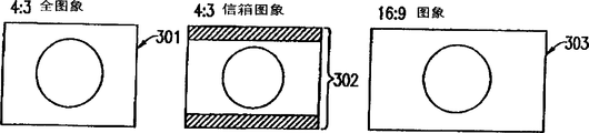
As shown in Figure 3A, coil 1 vision signal of reproducing certainly three kinds of forms are arranged.The representative of the vision signal of first kind of form has a kind of image of filling up 4: 3 full frame information (below be referred to as 4: 3 full figures resemble 301).The representative of the vision signal of second kind of form is at one 16: 9 images of the centre of 4: 3 screens, and the upper and lower hides hypographous a kind of image (below be referred to as 4: 3 mailbox images 302).The representative of the vision signal of the third form has a kind of image of filling up 16: 9 full frame information (below be referred to as 16: 9 full figures resemble 303).
Fig. 3 B shows the ratio of width to height of interlaced scanning video monitor 103.Shown in Fig. 3 B, the monitor that is used for interlaced scanning video monitor 103 has two types, and the ratio of width to height two another kind of monitors 305 that a kind of monitor 304 had 4: 3 have the ratio of width to height of 16: 9.
Fig. 3 C shows the ratio of width to height of progressive scanned video monitor 104.Shown in Fig. 3 B, the monitor that is used for progressive scanned video monitor 104 has two types, and the ratio of width to height two another kind of monitors 307 that a kind of monitor 306 had 4: 3 have the ratio of width to height of 16: 9.
This interlaced video signal reproducing circuit 4 reads the vision signal that dish 1 writes down from the output of pick-up head 2, reproduces an interlaced video signal, and the result is exported to interlacing scan aspect ratio conversion circuit 6.Data determines that circuit 5 reads definite sign from the output of pick-up head 2, determines the type of this vision signal, and the result is exported to interlacing scan control circuit 12 as definite signal.
The user uses interlacing scan the ratio of width to height specified portions 13, specifies the type (the ratio of width to height) of the interlaced scanning video monitor 103 of output interlaced video signal.Interlacing scan control circuit 12 is according to definite signal of determining circuit 5 outputs from data with by the type (the ratio of width to height) of the interlaced scanning video monitor 103 of interlacing scan the ratio of width to height specified portions 13 appointments, control interlacing scan aspect ratio conversion circuit 6.
Fig. 4 is the summary schematic diagram of the operation of explanation interlacing scan aspect ratio conversion circuit 6.Suppose that this interlaced scanning video monitor 103 has the ratio of width to height of 4: 3, interlacing scan aspect ratio conversion circuit 6 has the function of compressing 16: 9 images 303 of the ratio of width to height with 16: 9 in vertical direction.Particularly, in order to show 16: 9 images 303 with correct the ratio of width to height on 4: 3 monitor 304,4 line information of incoming video signal are carried out Filtering Processing so that generate the information of 3 lines.Carry out such processing for whole screen, so that compress whole screen in vertical direction.In the case, the image of demonstration has correct the ratio of width to height (16: 9), but leaves blank in the upper and lower.These parts are rendered as the image of black.This aspect ratio conversion function can use interlacing scan control circuit 12 to switch between an operating state and an off position.Under off position, interlacing scan aspect ratio conversion circuit 6 is exported the interlaced video signal that receives and is not carried out aspect ratio conversion.
In Fig. 1, the monitor 305 that the user uses interlacing scan the ratio of width to height specified portions 13 will be used to export the monitor with 4: 3 the ratio of width to height 304 of an image or have 16: 9 the ratio of width to height is appointed as the ratio of width to height of 16: 9 images 303.Data is determined circuit 5 the ratio of width to height with eikongen, and one of promptly 4: 3 full frame 301 or 4: 3 mailbox screens 302 or 16: 9 screens 303 are exported to interlacing scan control circuit 12.
Interlacing scan control circuit 12 is exported to interlacing scan aspect ratio conversion circuit 6 with following three instructions.
(1) when data determines that circuit 5 determines that the ratio of width to height of eikongen is 4: 3 full screen images or 4: 3 mailbox screen images, interlacing scan control circuit 12 outputs first instruction makes the aspect ratio conversion function of interlacing scan aspect ratio conversion circuit 6 be in off position.
(2) determine circuit 5 when data and determine that the ratio of width to height of eikongens is that 16: 9 and interlacing scan the ratio of width to height specified portions are when specifying the type of interlaced scanning video monitor to be 16: 9 interlaced scanning video monitors, interlacing scan control circuit 12 outputs second instruction makes the aspect ratio conversion function of interlacing scan aspect ratio conversion circuit 6 be in off position.
(3) determine circuit 5 when data and determine that the ratio of width to height of eikongens is that 16: 9 and interlacing scan the ratio of width to height specified portions are when specifying the type of interlaced scanning video monitor to be 4: 3 interlaced scanning video monitors, interlacing scan control circuit 12 outputs the 3rd instruction makes that the aspect ratio conversion function of interlacing scan aspect ratio conversion circuit 6 is in running order.
Encoder 7 converts the output of interlacing scan aspect ratio conversion circuit 6 to the ntsc video form.Encoder 7 is exported to interlaced scanning video monitor 103 by the interleaved image that interleaved visual lead-out terminal 8 will have the NTSC form.
Fig. 5 A to 5C is the summary schematic diagram that is used to illustrate 4: 3 full figure elephants that show on the interlaced scanning video monitor.Shown in Fig. 5 A, be presented at 4: 3 full figures on this 4: 3 interlaced scanning video monitors 304 and resemble and have correct the ratio of width to height.Yet shown in Fig. 5 B, 4: 3 full figures that shown by 16: 9 interlaced scanning video monitors 305 resemble does not have correct the ratio of width to height, so that the image that shows is flatly expanded.Interlaced scanning video monitor 305 comprised 4: 3 output translation functions in 16: 9, because standard the ratio of width to height of interlaced video signal is 4: 3.Shown in Fig. 5 C, interlaced scanning video monitor 305 can use 4: 3 output translation functions to show that with correct 4: 3 the ratio of width to height 4: 3 full figures resemble 301B in 16: 9.
Fig. 6 A to 6D is the summary schematic diagram that is used to illustrate 4: 3 mailbox images that show on the interlaced scanning video monitor.As shown in Figure 6A, 4: 3 mailbox images 302 that are presented on this 4: 3 interlaced scanning video monitors 304 have correct the ratio of width to height.Yet, shown in the B, do not have correct the ratio of width to height by 4: 3 mailbox image 302A that show on 16: 9 interlaced scanning video monitors 305, so that the image that shows is flatly expanded as figure.Interlaced scanning video monitor 305 comprises 4: 3 mailbox image output translation functions, because standard the ratio of width to height of interlaced video signal is 4: 3.Shown in Fig. 5 C, have 4: 3 mailbox image output translation functions, mailbox image 302A was expanded up and down so that 4: 3 mailbox image 302B fill up full frame in 4: 3.Therefore, 4: 3 the ratio of width to height that interlaced scanning video monitor 305 can be correct show 4: 3 mailbox images.Eikongen can have the telltale title information 302C in the bottom of image blank parts.In the case, expanded up and down so that 4: 3 mailbox image 302B fill up full frame and so that the ratio of width to height was shown in correct 16: 9, telltale title information 302C disappeared as 4: 3 mailbox image 302A.For avoiding this situation, interlaced scanning video monitor 305 has one and switches function, make telltale title information 302 by upward displacement so that on screen as seen.
Fig. 7 A to 7C is the summary schematic diagram that is used to illustrate 16: 9 images that show on the interlaced scanning video monitor.Shown in Fig. 7 A, 16: 9 images are displayed on this 4: 3 interlaced scanning video monitors 304 by its former state, and this image does not have correct the ratio of width to height so that the image that shows is vertically expanded.Yet, if the user instructs interlacing scan the ratio of width to height specified portions 13 to wait that the interlacing scan monitor of the equipment of being connected to 100 is interlacing scan monitors 305 of 16: 9, this interlacing scan aspect ratio conversion circuit 6 activated and the ratio of width to height is converted so that image (16: 9 visual 303B) is correctly shown, shown in Fig. 7 B.In addition, shown in Fig. 7 C, this 16: 9 interlacing scan monitors 305 show 1 with correct the ratio of width to height of 16: 9: 9 images 303.
Particularly, in Ref reproduction equipment 100, the interlaced scanning video monitor can two kinds of video-frequency monitors, and promptly 4: 3 monitor and 16: 9 monitor show three kinds of eikongens with correct the ratio of width to height, and promptly 4: 3 full figures resemble, 4: 3 mailbox images, and the combination in any of 16: 9 images.
The output of interlacing scan aspect ratio conversion circuit 6 is transfused to the vision signal change-over circuit 9 of lining by line scan.The vision signal change-over circuit 9 of lining by line scan converts the interlaced video signal of input to line by line scan vision signal, and exports this result.
Fig. 8 A to 8D is the summary schematic diagram of operation of the aspect ratio conversion circuit 16 of explanation Ref reproduction equipment 100 of the present invention.
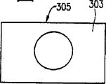
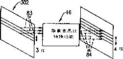
Referring to Fig. 8 A, aspect ratio conversion circuit 16 has and compresses in the horizontal direction that 4: 3 full figures resemble so that the horizontal aspect ratio conversion function of 4: 3 full figure elephants that showed on the progressive scanned video monitor 307 at 16: 9 with correct the ratio of width to height.Particularly, shown in Fig. 8 A, 4: 3 full figures of input progressive-scan video signal resemble 4 Pixel Information 81 that comprise in 301 and are carried out Filtering Processing so that generate the information 82 of 3 pixels.Resemble 301 for whole 4: 3 full figures and carry out such processing, resemble 301 so that compress whole 4: 3 full figures in the horizontal direction.In the case, 4: 3 full figures resemble 301 4: 3 correct the ratio of width to height that are converted on 16: 9 progressive scanned video monitors 307, make it leave blank in the upper and lower but 4: 3 full figures resemble 301 level compression.These parts are rendered as the image of black.
Referring to Fig. 8 B, aspect ratio conversion circuit 16 has and compresses 4: 3 mailbox image in vertical direction so that the vertical aspect ratio conversion function of 4: 3 mailbox images that showed on the progressive scanned video monitor 307 at 16: 9 with correct the ratio of width to height.Particularly, shown in Fig. 8 B, 3 Pixel Information 83 that the input progressive-scan video signal in mailbox image 302 comprises at 4: 3 are carried out Filtering Processing so that generate the information 84 of 4 pixels.Carry out such one for whole 4: 3 mailbox images 302 and handle, so that expand whole 4: 3 mailbox images 302 in vertical direction, thus 4: 3 mailbox images 302 are converted into 16: 9 screens.
Shown in Fig. 8 C, aspect ratio conversion circuit 16 has vertical display position shift function, make 4: 3 mailbox images 801 be expanded in vertical direction, 4: 3 mailbox images 801 of expansion are shifted so that the vertical middle body 803 of 4: 3 mailbox images 801 is moved to middle position 804 (a predetermined amount moves up).This function is to realize with respect to the position of a vertical synchronizing signal by changing display image signals.
These three aspect ratio conversion functions respectively use control circuit to select a job or an off position.When all translation functions were in off position, aspect ratio conversion circuit 16 was exported the progressive-scan video signal of an input and is not carried out aspect ratio conversion.
In Fig. 1, the user uses the type of the interlaced scanning video monitor 103 that interlacing scan the ratio of width to height specified portions 13 will be used to show to be appointed as 4: 3 interlaced scanning video monitors 304 or 16: 9 interlaced scanning video monitors 305.The user specifies in specified portions 14 also progressive scanned video monitor 104 is whether 4: 3 progressive scanned video monitors 306 or 16: 9 progressive scanned video monitors 307 and vertical display position displacement are carried out.On the other hand, data is determined the type of circuit 5 with image source, and one of promptly 4: 3 full frame 301 or 4: 3 mailbox screens 302 or 16: 9 screens 303 are exported to interlacing scan control circuit 12 and control circuit 15.
(1) determines circuit 5 when data and determine that the ratio of width to height of eikongens is that 4: 3 full figures resemble 301 or 4: 3 mailbox screen images 302 and when being 4: 3 progressive scanned video monitors 306 by the type of the progressive scanned video monitor 104 of specified portions 14 appointments, control circuit 15 makes the level of aspect ratio conversion circuit 16 be in off position with vertical aspect ratio conversion function with vertical display position shift function.
(2) determine circuit 5 when data and determine that the ratio of width to height of eikongens is that 4: 3 full figures resemble 301 and when being 16: 9 progressive scanned video monitors 307 by the type of the progressive scanned video monitor 104 of specified portions 14 appointments, control circuit 15 makes the level of aspect ratio conversion circuit 16 and vertical aspect ratio conversion function distinguish in running order and off position.
(3) determine circuit 5 when data and determine that the ratio of width to height of eikongens is 4: 3 mailbox images 302, is 16: 9 progressive scanned video monitors 307 and when in specified portions 14 upright position not being set and moving by the type of the progressive scanned video monitor 104 of specified portions 14 appointments that control circuit 15 makes the level of aspect ratio conversion circuit 16, vertical aspect ratio conversion function and vertical display position shift function distinguish in running order, off position and off position.
(4) determine circuit 5 when data and determine that the ratio of width to height of eikongens is that 4: 3 full figures resemble 301 or 4: 3 mailbox screen images 302, are 16: 9 progressive scanned video monitors 306 and when the upright position displacement is set by the type of the progressive scanned video monitor 104 of specified portions 14 appointments in specified portions 14, control circuit 15 makes that the vertical aspect ratio conversion function of aspect ratio conversion circuit 314 is in running order with vertical display position shift function and makes the horizontal aspect ratio conversion function of aspect ratio conversion circuit 314 be in off position.
(5) when data determine the ratio of width to height of the eikongen of circuit 5 be 16: 9 visual 303 the time, control circuit 15 makes the level of aspect ratio conversion circuit 16 be in off position with vertical aspect ratio conversion function and vertical display position shift function.
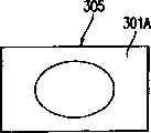
Fig. 9 A to 9C is the summary schematic diagram that is used to illustrate 4: 3 full figure elephants that show on the progressive scanned video monitor.Shown in Fig. 9 A, be presented at 4: 3 full figures on this 4: 3 progressive scanned video monitors 306 and resemble and have correct the ratio of width to height.Yet shown in Fig. 9 B, 4: 3 full figures that shown by 16: 9 progressive scanned video monitors 307 resemble 301D and do not have correct the ratio of width to height, so that the image that shows is flatly expanded.Progressive scanned video monitor 307 comprised 4: 3 output translation functions in 16: 9, because standard the ratio of width to height of progressive-scan video signal is 4: 3.Shown in Fig. 9 C, progressive scanned video monitor 307 can use 4: 3 output translation functions to show that with correct 4: 3 the ratio of width to height 4: 3 full figures resemble 301E in 16: 9.
Figure 10 A to 10F is the summary schematic diagram that is used to illustrate 4: 3 mailbox images that show on the progressive scanned video monitor.Shown in Figure 10 A, 4: 3 mailbox images 302 that are presented on this 4: 3 progressive scanned video monitors 306 have correct the ratio of width to height.Yet shown in Figure 10 B, 4: 3 mailbox image 302A that shown by 16: 9 progressive scanned video monitors 307 do not have correct the ratio of width to height, so that the image that shows is flatly expanded.Progressive scanned video monitor 307 comprises 4: 3 mailbox image output translation functions, because standard the ratio of width to height of progressive-scan video signal is 4: 3.Shown in Figure 10 C, have 4: 3 mailbox image output translation functions, mailbox image 302A was expanded up and down so that 4: 3 mailbox image 302F fill up full frame in 4: 3.Therefore, 16: 9 the ratio of width to height that progressive scanned video monitor 306 can be correct show 4: 3 mailbox images.
Shown in Figure 10 D, some eikongens can have the telltale title information 302H in the bottom of image blank parts.In the case, shown in Figure 10 E, when 4: 3 mailbox image 302G is expanded up and down, disappear at the telltale title information 302C of the bottom blank parts of 4: 3 mailbox image 302G.In the case, specified portions 14 is specified vertical display position displacement.Therefore, shown in Figure 10 F, 4: 3 mailbox images of aspect ratio conversion circuit 16 upward displacements 302G is so that can see telltale title information 302H at 16: 9 on the progressive scanned video monitor 307.
Figure 11 A to 11C is the summary schematic diagram that is used to illustrate 16: 9 images that show on the progressive scanned video monitor.Shown in Figure 11 A, 16: 9 visual 303F are displayed on this 4: 3 progressive scanned video monitors 306, and this image does not have correct the ratio of width to height so that the image that shows is vertically expanded.Yet, if the user instructs specified portions 14 to wait that the monitor of lining by line scan of the equipment of being connected to 100 is 16: 9 the monitors 307 of lining by line scan, aspect ratio conversion circuit 6 activated and the ratio of width to height is converted so that 16: 9 visual 303G are correctly shown, shown in Figure 11 B.In addition, shown in Figure 11 C, the monitor 307 of lining by line scan in these 16: 9 shows 1 with correct the ratio of width to height of 16: 9: 9 images 303.
As mentioned above, in Ref reproduction equipment 100 of the present invention, progressive scanned video monitor 104 can with 4: 3 progressive scanned video monitors 306 and 16: 9 progressive scanned video monitors 307 with correct the ratio of width to height show that 4: 3 full figures resemble 301, the combination in any of the eikongen of 4: 3 mailbox images 302 and 16: 9 images 303.
Notice that in this embodiment, eikongen is limited to 3 types, promptly 4: 3 full figures resemble, 4: 3 mailbox images, 16: 9 images.Yet, four kinds or more kinds of image source can be arranged.In this embodiment, two kinds of the ratio of width to height have been used, promptly 4: 3 and 16: 9.If the aspect ratio conversion function of aspect ratio conversion circuit is changed according to the ratio of width to height of eikongen, the ratio of width to height is not limited to two kinds.The present invention can be used for the situation that three kinds or more kinds of the ratio of width to height are used.
And, in Fig. 1, each element, promptly data determines that circuit 5, aspect ratio conversion part 102, encoder 7 and aberration transducer 10 are to adopt for example form of circuit of hardware, but can be replaced by software.
The line number that aspect ratio conversion circuit 16 can be scheduled to visual display position upward displacement.Replacedly, the line number that is shifted of visual display position is variable so that the upward displacement amount can be changed.
And, in these examples, the vision signal that is recorded on the dish medium is described.The present invention also can be used for the information signal that comprises in the vision signal that writes down in other the band medium and the information signal by transmission such as satellite broadcasting and terrestrial broadcastings.
As mentioned above, according to the present invention, provide a kind of Ref reproduction equipment, its available video-frequency monitor with different the ratio of width to height has the combination in any of some eikongens of different the ratio of width to height with correct the ratio of width to height demonstration.
And, according to the present invention, provide a kind of Ref reproduction equipment, wherein when the mailbox image had a telltale title in the bottom of screen in 4: 3, can prevent the disappearance of telltale title.
For those skilled in the art, do not exceed the spirit and scope of the present invention and realize that other remodeling of the present invention are obvious.Therefore, the scope of not expecting claims is subjected to the restriction in this description of doing, and expectation obtains sensu lato explanation.
Claims (13)
1, a kind of Ref reproduction equipment is used to receive an information signal, and this information signal comprises definite signal of the type of a vision signal and this vision signal of indication, and reproduces this vision signal that comprises in this information signal, and this equipment comprises:
One conversion portion is used for converting this vision signal to progressive-scan video signal; With
One aspect ratio conversion part is used to change the ratio of width to height of the progressive-scan video signal of exporting from this conversion portion and the progressive-scan video signal of conversion is exported to a progressive scanned video monitor,
Wherein this aspect ratio conversion part is changed the ratio of width to height of this progressive-scan video signal according to the definite signal of the type of this vision signal of indication and the monitor information of the type of this progressive scanned video monitor of indication.
2, according to the Ref reproduction equipment of claim 1, wherein this aspect ratio conversion partly change this progressive-scan video signal the ratio of width to height so that this progressive-scan video signal be displayed on the progressive scanned video monitor with correct the ratio of width to height.
3, according to the Ref reproduction equipment of claim 1, wherein:
This ratio of width to height comprises first and second the ratio of width to height;
This vision signal comprises that representative has first image of first the ratio of width to height and has the vision signal of second image of second the ratio of width to height;
This progressive scanned video monitor comprises first monitor with first the ratio of width to height and second monitor with second the ratio of width to height; And
When definite signal indicated first image to have first the ratio of width to height and this monitor information to indicate second monitor to have second the ratio of width to height, this aspect ratio conversion was partly changed the ratio of width to height of this progressive-scan video signal.
4, according to the Ref reproduction equipment of claim 3, wherein:
This first image comprises that the full figure with first the ratio of width to height resembles; And
When definite signal indicated this full figure to resemble, this aspect ratio conversion was partly changed the ratio of width to height of this progressive-scan video signal so that resembled in the horizontal direction by this full figure of progressive-scan video signal representative and to be compressed.
5, according to the Ref reproduction equipment of claim 4, wherein:
This full figure that second monitor with second the ratio of width to height will have first the ratio of width to height in the horizontal direction resembles expansion one factor (M/N), and wherein M and N are integer, and M>N; And
This aspect ratio conversion part resembles this full figure compression one factor (N/M) in the horizontal direction so that show that this full figure with first the ratio of width to height resembles with correct the ratio of width to height on second monitor of second the ratio of width to height having.
6, according to the Ref reproduction equipment of claim 4, wherein this aspect ratio conversion part will resemble the blank parts that compression in the horizontal direction causes by this full figure and be rendered as a black image.
7, according to the Ref reproduction equipment of claim 3, wherein:
This first image comprises a mailbox image, and this mailbox image comprises first the ratio of width to height; And
When this determined that signal is indicated this mailbox image, aspect ratio conversion was partly changed the ratio of width to height of this progressive-scan video signal so that be expanded in vertical direction by this mailbox image of progressive-scan video signal representative.
8, according to the Ref reproduction equipment of claim 7, wherein:
Second monitor with second the ratio of width to height will have this mailbox image expansion one factor (M/N) of first the ratio of width to height in the horizontal direction, and wherein M and N are integer, and M>N; And
This aspect ratio conversion part is expanded factor (M/N) so that have this mailbox image that demonstration has first the ratio of width to height on second monitor of second the ratio of width to height with correct the ratio of width to height with this mailbox image in vertical direction.
9, according to the Ref reproduction equipment of claim 7, wherein:
The telltale title that this mailbox image comprises at an upper portion thereof or the bottom shows; And
This aspect ratio conversion transposition of partial, is prevented to disappear on second monitor with second the ratio of width to height that telltale title comprises in the progressive scanned video monitor so that when this mailbox image is expanded in vertical direction by this mailbox image of progressive-scan video signal representative.
10, according to the Ref reproduction equipment of claim 3, wherein first the ratio of width to height is 4: 3 and second the ratio of width to height is 16: 9.
11, according to the Ref reproduction equipment of claim 1, wherein this aspect ratio conversion partly comprises:
One aspect ratio conversion circuit is used to change the ratio of width to height of progressive-scan video signal and the progressive-scan video signal of conversion is exported to the progressive scanned video monitor;
One specified portions is used to specify the monitor information of the type of indication progressive scanned video monitor; With
One control circuit is used for according to determining signal and by the monitor information of this specified portions appointment, controlling this aspect ratio conversion circuit.
12, according to the Ref reproduction equipment of claim 1, wherein this conversion portion comprises:
One interlaced video signal reproducing part is used to reproduce as having the vision signal of the interlaced video signal of 60 of per seconds;
One interlacing scan aspect ratio conversion part is used to change the ratio of width to height by the interlaced video signal of this interlaced video signal reproducing part reproduction; With
One progressive-scan video signal conversion portion is used to change interlaced video signal, and the ratio of width to height of this interlaced video signal is converted into progressive-scan video signal by this interlaced video signal reproducing part.
13, according to the Ref reproduction equipment of claim 12, wherein this conversion portion also comprises:
One interlacing scan specified portions is used to specify the interlacing scan monitor information of the type of indication interlaced scanning video monitor; With
One interlacing scan control circuit is used for according to determining signal and by the interlacing scan monitor information of this interlacing scan specified portions appointment, controlling this interlacing scan aspect ratio conversion part.
Applications Claiming Priority (2)
| Application Number | Priority Date | Filing Date | Title |
|---|---|---|---|
| JP2000196084A JP4356202B2 (en) | 2000-06-29 | 2000-06-29 | Video signal processing device |
| JP196084/2000 | 2000-06-29 |
Publications (1)
| Publication Number | Publication Date |
|---|---|
| CN1344109A true CN1344109A (en) | 2002-04-10 |
Family
ID=18694641
Family Applications (1)
| Application Number | Title | Priority Date | Filing Date |
|---|---|---|---|
| CN01119944.XA Pending CN1344109A (en) | 2000-06-29 | 2001-06-29 | Ref reproduction equipment |
Country Status (5)
| Country | Link |
|---|---|
| US (1) | US7099570B2 (en) |
| EP (1) | EP1168834B1 (en) |
| JP (1) | JP4356202B2 (en) |
| CN (1) | CN1344109A (en) |
| CA (1) | CA2351845C (en) |
Cited By (2)
| Publication number | Priority date | Publication date | Assignee | Title |
|---|---|---|---|---|
| CN100344156C (en) * | 2002-12-27 | 2007-10-17 | 株式会社东芝 | Information reproducing apparatus and method thereof |
| CN102438157A (en) * | 2010-08-18 | 2012-05-02 | 索尼公司 | Image processing device, method, and program |
Families Citing this family (15)
| Publication number | Priority date | Publication date | Assignee | Title |
|---|---|---|---|---|
| US20040213542A1 (en) * | 2003-04-22 | 2004-10-28 | Hiroshi Hamasaka | Apparatus and method to reproduce multimedia content for a multitude of resolution displays |
| WO2005001614A2 (en) * | 2003-06-02 | 2005-01-06 | Disney Enterprises, Inc. | System and method of dynamic interface placement based on aspect ratio |
| US20050179817A1 (en) * | 2004-01-14 | 2005-08-18 | Matsushita Electric Industrial Co., Ltd. | Video signal display unit |
| US7911536B2 (en) * | 2004-09-23 | 2011-03-22 | Intel Corporation | Screen filled display of digital video content |
| CN100518285C (en) * | 2004-09-29 | 2009-07-22 | Tcl王牌电子(深圳)有限公司 | Method for realizing TV set progressive scanning digital normalization |
| JP4813370B2 (en) * | 2004-12-02 | 2011-11-09 | ソニー株式会社 | Video signal processing apparatus, video signal processing method, program, and recording medium |
| TWI262725B (en) * | 2005-06-30 | 2006-09-21 | Cheertek Inc | Video decoding apparatus and digital audio and video display system capable of controlling presentation of subtitles and method thereof |
| US20080317120A1 (en) * | 2007-06-25 | 2008-12-25 | David Drezner | Method and System for MPEG2 Progressive/Interlace Type Detection |
| US20100179213A1 (en) * | 2008-11-11 | 2010-07-15 | Mirna Therapeutics, Inc. | Methods and Compositions Involving miRNAs In Cancer Stem Cells |
| CN102172033B (en) | 2009-06-17 | 2013-07-17 | 松下电器产业株式会社 | Reproduction device, recording method abd recording medium reproduction system |
| US20110013888A1 (en) * | 2009-06-18 | 2011-01-20 | Taiji Sasaki | Information recording medium and playback device for playing back 3d images |
| US9043714B1 (en) * | 2011-01-07 | 2015-05-26 | Google Inc. | Adaptive user interface for widescreen devices |
| US20140092992A1 (en) | 2012-09-30 | 2014-04-03 | Microsoft Corporation | Supplemental enhancement information including confidence level and mixed content information |
| US9756282B2 (en) * | 2012-11-20 | 2017-09-05 | Sony Corporation | Method and apparatus for processing a video signal for display |
| KR102227088B1 (en) | 2014-08-11 | 2021-03-12 | 엘지전자 주식회사 | Device and control method for the device |
Family Cites Families (8)
| Publication number | Priority date | Publication date | Assignee | Title |
|---|---|---|---|---|
| JP2842913B2 (en) | 1990-01-24 | 1999-01-06 | 株式会社日立製作所 | Wide television signal processing circuit |
| US5673086A (en) * | 1990-10-05 | 1997-09-30 | Canon Kabushiki Kaisha | Image aspect ratio conversion processing apparatus |
| US5347318A (en) * | 1992-06-16 | 1994-09-13 | Canon Kabushiki Kaisha | Apparatus for processing video signals having different aspect ratios |
| JP3240697B2 (en) * | 1992-08-11 | 2001-12-17 | 松下電器産業株式会社 | Video magnifier |
| JP3282768B2 (en) | 1994-06-15 | 2002-05-20 | ソニー株式会社 | Television display method |
| JP3362538B2 (en) * | 1994-12-06 | 2003-01-07 | ソニー株式会社 | Video signal processing device and video signal reproducing device |
| US5745643A (en) * | 1995-04-06 | 1998-04-28 | Kabushiki Kaisha Toshiba | System for and method of reproducing playback data appropriately by the use of attribute information on the playback data |
| JP3953561B2 (en) | 1996-10-15 | 2007-08-08 | 株式会社日立製作所 | Image signal format conversion signal processing method and circuit |
-
2000
- 2000-06-29 JP JP2000196084A patent/JP4356202B2/en not_active Expired - Fee Related
-
2001
- 2001-06-28 US US09/893,939 patent/US7099570B2/en not_active Expired - Fee Related
- 2001-06-28 EP EP01114824A patent/EP1168834B1/en not_active Expired - Lifetime
- 2001-06-28 CA CA002351845A patent/CA2351845C/en not_active Expired - Fee Related
- 2001-06-29 CN CN01119944.XA patent/CN1344109A/en active Pending
Cited By (3)
| Publication number | Priority date | Publication date | Assignee | Title |
|---|---|---|---|---|
| CN100344156C (en) * | 2002-12-27 | 2007-10-17 | 株式会社东芝 | Information reproducing apparatus and method thereof |
| CN102438157A (en) * | 2010-08-18 | 2012-05-02 | 索尼公司 | Image processing device, method, and program |
| CN102438157B (en) * | 2010-08-18 | 2015-06-17 | 索尼公司 | Image processing device and method |
Also Published As
| Publication number | Publication date |
|---|---|
| US7099570B2 (en) | 2006-08-29 |
| CA2351845A1 (en) | 2001-12-29 |
| JP4356202B2 (en) | 2009-11-04 |
| US20020009295A1 (en) | 2002-01-24 |
| EP1168834B1 (en) | 2013-02-20 |
| CA2351845C (en) | 2008-09-30 |
| EP1168834A3 (en) | 2002-11-06 |
| EP1168834A2 (en) | 2002-01-02 |
| JP2002016884A (en) | 2002-01-18 |
Similar Documents
| Publication | Publication Date | Title |
|---|---|---|
| CN1344109A (en) | Ref reproduction equipment | |
| KR100227932B1 (en) | Picture information encoding/decoding system and its recording media and transmission system | |
| CN1053310C (en) | Asymmetric picture compression | |
| CN1165161C (en) | Image display method and equipment | |
| CN1649397A (en) | Device and method for processing video signal | |
| CN1137208A (en) | Double picture TV set | |
| CN1607819A (en) | Image mixing method, and mixed image data generation device | |
| CN1812524A (en) | Integrated multimedia signal processing system using centralized processing of signals | |
| CN1685714A (en) | On screen display control image display apparatus and image display method | |
| CN1604639A (en) | Miniaturized video feed generation and user-interface | |
| CN1225918C (en) | Image signal processor and method | |
| CN1113062A (en) | TV set with video disc playing apparatus | |
| CN1181670C (en) | Overlay image processor and display device | |
| CN1225120C (en) | Image processing device, image processing method, recording medium and program | |
| CN1311683C (en) | Characteristic correcting device | |
| WO2000038419A1 (en) | Video signal reproducing device | |
| CN1503554A (en) | Device and method for making television advertisement and inserting into television program | |
| JP2005311776A (en) | Image reproduction device | |
| CN1222163C (en) | Magnetic medium recording/reproducing apparatus | |
| CN1283362A (en) | Method and apparatus for reducing flicker in television display of network application data | |
| CN1160325A (en) | Composite video apparatus | |
| CN1283363A (en) | Flicker filter and interlacer implamented in television system displaying network application data | |
| KR100518125B1 (en) | Business method for monitoring multi-media playback by television and the mobile terminal therefor | |
| CN1578425A (en) | Television receiver and control method thereof | |
| CN1700751A (en) | Picture in picture processing apparatus and method for image display device |
Legal Events
| Date | Code | Title | Description |
|---|---|---|---|
| C10 | Entry into substantive examination | ||
| SE01 | Entry into force of request for substantive examination | ||
| C06 | Publication | ||
| PB01 | Publication | ||
| C12 | Rejection of a patent application after its publication | ||
| RJ01 | Rejection of invention patent application after publication |