JP4356202B2 - Video signal processing device - Google Patents
Video signal processing device Download PDFInfo
- Publication number
- JP4356202B2 JP4356202B2 JP2000196084A JP2000196084A JP4356202B2 JP 4356202 B2 JP4356202 B2 JP 4356202B2 JP 2000196084 A JP2000196084 A JP 2000196084A JP 2000196084 A JP2000196084 A JP 2000196084A JP 4356202 B2 JP4356202 B2 JP 4356202B2
- Authority
- JP
- Japan
- Prior art keywords
- aspect ratio
- video signal
- video
- monitor
- image
- Prior art date
- Legal status (The legal status is an assumption and is not a legal conclusion. Google has not performed a legal analysis and makes no representation as to the accuracy of the status listed.)
- Expired - Fee Related
Links
Images


Classifications
-
- H—ELECTRICITY
- H04—ELECTRIC COMMUNICATION TECHNIQUE
- H04N—PICTORIAL COMMUNICATION, e.g. TELEVISION
- H04N7/00—Television systems
- H04N7/01—Conversion of standards, e.g. involving analogue television standards or digital television standards processed at pixel level
- H04N7/0117—Conversion of standards, e.g. involving analogue television standards or digital television standards processed at pixel level involving conversion of the spatial resolution of the incoming video signal
- H04N7/012—Conversion between an interlaced and a progressive signal
-
- H—ELECTRICITY
- H04—ELECTRIC COMMUNICATION TECHNIQUE
- H04N—PICTORIAL COMMUNICATION, e.g. TELEVISION
- H04N7/00—Television systems
- H04N7/01—Conversion of standards, e.g. involving analogue television standards or digital television standards processed at pixel level
- H04N7/0117—Conversion of standards, e.g. involving analogue television standards or digital television standards processed at pixel level involving conversion of the spatial resolution of the incoming video signal
- H04N7/0122—Conversion of standards, e.g. involving analogue television standards or digital television standards processed at pixel level involving conversion of the spatial resolution of the incoming video signal the input and the output signals having different aspect ratios
-
- H—ELECTRICITY
- H04—ELECTRIC COMMUNICATION TECHNIQUE
- H04N—PICTORIAL COMMUNICATION, e.g. TELEVISION
- H04N9/00—Details of colour television systems
- H04N9/79—Processing of colour television signals in connection with recording
- H04N9/7921—Processing of colour television signals in connection with recording for more than one processing mode
-
- H—ELECTRICITY
- H04—ELECTRIC COMMUNICATION TECHNIQUE
- H04N—PICTORIAL COMMUNICATION, e.g. TELEVISION
- H04N21/00—Selective content distribution, e.g. interactive television or video on demand [VOD]
- H04N21/40—Client devices specifically adapted for the reception of or interaction with content, e.g. set-top-box [STB]; Operations thereof
- H04N21/47—End-user applications
- H04N21/488—Data services, e.g. news ticker
- H04N21/4884—Data services, e.g. news ticker for displaying subtitles
-
- H—ELECTRICITY
- H04—ELECTRIC COMMUNICATION TECHNIQUE
- H04N—PICTORIAL COMMUNICATION, e.g. TELEVISION
- H04N5/00—Details of television systems
- H04N5/76—Television signal recording
- H04N5/84—Television signal recording using optical recording
- H04N5/85—Television signal recording using optical recording on discs or drums
Description
【0001】
【発明の属する技術分野】
本発明は、テープ媒体もしくはディスク媒体等に記録、または衛星放送もしくは地上波放送など、映画素材やビデオ素材等様々な映像情報を転送して映像信号を順次走査出力する映像信号処理装置に関する。
【0002】
【従来の技術】
従来、テープ媒体もしくはディスク媒体に記録、または衛星放送、有線放送もしくは地上波放送等の映像出力は、テレビ受像機で再生出来るよう飛び越し走査で出力されるのが普通であるが、近年、マルチスキャン対応のモニタ、プロジェクタまたはコンピュータ用モニタ等の普及に伴って、これらの飛び越し走査映像信号を順次走査信号に変換する映像信号再生装置が導入されつつある。
【0003】
図12は、本発明に関わる技術の従来の一例として、映像信号と当該映像信号のアスペクト比を判別する判別フラグとを有し、円盤状のディスクに収録された情報信号を再生する映像信号再生装置の構成を示すブロック図である。図12において、1はディスクで、映像信号と、当該映像信号のアスペクト比を示す判別フラグとが、予め記録(または再生)に適した信号形態に符号化され、変調されて記録されている。2はピックアップで、ディスク1に記録された情報信号を電気的信号に変換する。3はディスク回転装置で、ディスク1を再生に適した回転数で回転させる。4は飛び越し走査映像信号再生回路で、ディスク1に記録された映像信号を復調し、復号し、飛び越し走査映像信号として出力する。5は素材判別回路で、ピックアップ2の出力より、ディスク1に記録された判別フラグを読み取る。
【0004】
6は第1のアスペクト比変換回路で、第1の制御回路12により制御され、入力される映像信号のアスペクト比を変換して出力する。7はエンコーダで、飛び越し走査映像信号をNTSCビデオフォーマットに変換し出力する。8は飛び越し走査映像出力端子で、これより再生された飛び越し走査映像出力が、飛び越し走査映像用モニタ(図示は省略)に出力される。
【0005】
9は順次走査映像信号変換回路で、第1のアスペクト比変換回路6の出力を順次走査映像信号に変換し出力する。10は色差コンバータで、順次走査映像信号変換回路9の出力をアナログ色差信号に変換し出力する。11は順次走査映像出力端子で、これより変換された順次走査映像信号が、順次走査映像用モニタ(図示は省略)に出力される。
【0006】
12は第1の制御回路で、素材判別回路5の出力と、第1のアスペクト比設定手段13の出力とによって、第1のアスペクト比変換回路6を制御する。13は第1のアスペクト比設定手段であり、使用者が受像機のアスペクト比を設定する為のものである。
【0007】
以上の様に構成された従来の映像信号再生装置について、その動作を図13〜図21を参照しながら説明する。
【0008】
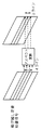
図13は、従来の映像信号再生装置のディスク1に記録される映像信号の構造を示す模式図である。飛び越し走査映像信号では、1/60秒で1フィールドの画像が構成され、それが2枚合わされて1フレームの画像となる。2枚のフィールドの縦画素数はそれぞれ240であり、互いの画素はそれぞれの画素の縦方向の間を埋めあう様な配置になる。順次走査映像信号では1フレームが1/60秒で縦画素数は480である。このように、垂直周波数は共に1/60秒であり、水平走査線数は飛び越し走査映像信号に比べ順次走査映像信号は倍になるので、水平走査周波数は、飛び越し走査映像信号が約15.75KHzであるのに対して、順次走査映像信号では約31.5KHzになる。
【0009】
図14は、従来の映像信号再生装置の映像信号のアスペクト比を示す模式図である。図14[a]に示す様に、ディスク1に記録された映像ソースの映像信号には3つの形態がある。図14[a]の(a−1)は4:3の画面一杯に情報を持つ素材(以後4:3フル画像と称す)であり、同図(a−2)は4:3の画面の中央部に16:9の画像を持ち、上下が黒で塗りつぶされた素材(以後4:3レターボックス画像と称す)であり、同図(a−3)は16:9の画面一杯に情報を持つ素材(以後16:9画像と称す)である。
【0010】
図14[b]は、飛び越し走査映像信号用モニタのアスペクト比を示す。図14[b]に示す様に、飛び越し走査映像信号用モニタには、同図(b−1)に示す4:3のアスペクト比のものと、同図(b−2)に示す16:9のアスペクト比のものとがある。
【0011】
図14[c]は、順次走査映像信号用モニタのアスペクト比を示す。図14[c]に示す様に、順次走査映像信号用モニタには、同図(c−1)に示す4:3のアスペクト比のものと、同図(c−2)に示す16:9のアスペクト比のものとがある。
【0012】
飛び越し走査映像信号再生回路4は、ピックアップ2の出力により、ディスク1に記録されている信号を読み取り、飛び越し映像信号を再生し、第1のアスペクト比変換回路6に出力する。素材判別回路5は、ピックアップ2の出力により判別フラグを読み取り映像信号の種類を判別し、判別信号として、第1の制御回路12に出力する。
【0013】
使用者は、映像信号を出画しようとしているモニタのアスペクト比を、第1のアスペクト比設定手段13により設定する。第1の制御回路12は、素材判別回路5の出力と第1のアスペクト比設定手段13の出力とによって、第1のアスペクト比変換回路6を制御する。
【0014】
図15は、従来の映像信号再生装置の第1のアスペクト比変換回路6の動作を説明する模式図である。第1のアスペクト比変換回路6は4:3のモニタを想定し、16:9のアスペクト比の素材を垂直方向に圧縮する機能を持つ。即ち、16:9の素材を4:3のモニタにて正しいアスペクト比で表示するために、入力される映像信号の4ライン分の情報からフィルタ処理を行い、3ライン分の情報を生成する。このような処理を全画面において行うと、画面全体が上下に圧縮され、アスペクト比的には正しく16:9の画面に変換できるが、上下に空白部分ができるので、その部分を黒画像とする。このアスペクト比変換機能は、第1の制御回路12によって、作動と非作動状態を選択する事ができる。非作動の場合には第1のアスペクト比変換回路6は、入力された映像信号のアスペクト比変換をせずにそのまま出力する。
【0015】
図12において、使用者は、出画しようとするモニタのアスペクト比が4:3であるか16:9であるかを、第1のアスペクト比設定手段13で設定する。一方、素材判別回路5は、映像ソースのアスペクト比が4:3フル画像なのか、4:3レターボックス画像なのか、16:9画像なのかの何れかを、第1の制御回路12に出力する。第1の制御回路12は、素材判別回路5が映像ソースのアスペクト比が4:3フル画像、もしくは4:3レターボックス画像を示している場合には、第1のアスペクト比変換回路6のアスペクト変換動作を非作動とする。また、第1の制御回路12は、素材判別回路5が映像ソースのアスペクト比が16:9を示している場合で、かつ第1のアスペクト比設定手段出力が16:9の場合には、第1のアスペクト比変換回路6のアスペクト比変換動作を非作動とする。なお、第1の制御回路12は、素材判別回路5が映像ソースのアスペクト比が16:9を示している場合で、かつ第1のアスペクト比設定手段出力が4:3の場合には、第1のアスペクト比変換回路6のアスペクト比変換動作を作動とする。
【0016】
エンコーダ7は、第1のアスペクト比変換回路6の出力をNTSCビデオフォーマットに変換し、飛び越し走査映像出力端子8より、飛び越し走査映像出力が飛び越し走査映像用モニタ(図示は省略)に出力される。
【0017】
次に、従来の映像信号再生装置における映像ソースが4:3フル画像、4:3レターボックス画像及び16:9画像それぞれについて、飛び越し走査映像用モニタの画角に対応する場合を図16〜図18、及び連続走査映像用モニタの画角に対応する場合を図19〜図21を用いて以下説明する。
【0018】
図16は、従来の映像信号再生装置における4:3フル画像の映像ソースの場合の、飛び越し走査映像用モニタに出画されるアスペクト比を説明する模式図である。図16(b−1)に示すように、4:3のモニタではアスペクト比が正しく表示されている。ところが、同図(b−2)に示すように、16:9のモニタではアスペクト比が正しく表示されず、横に引き延ばされた様に出画される。一方、飛び越し走査映像用モニタでは、従来の飛び越し走査映像信号の標準的アスペクト比が4:3のため、4:3出力切り替え機能を装備しており、飛び越し走査映像用モニタが備える4:3出力切り替え機能を使用することによって、同図(b−3)に示すように、正しく4:3のアスペクト比で表示されるようになる。
【0019】
図17は、従来の映像信号再生装置における4:3レターボックス画像の映像ソースの場合の、飛び越し走査映像用モニタに出画されるアスペクト比を説明する模式図である。図17(b−1)に示すように、4:3のモニタではアスペクト比が正しく表示されている。そころが、同図(b−2)に示すように、16:9のモニタではアスペクト比が正しく表示されず、横に引き延ばされた様に出画される。一方、飛び越し走査映像用モニタでは、従来の飛び越し走査映像信号の標準的アスペクト比が4:3のため、4:3レターボックス映像出力切り替え機能を装備しており、飛び越し走査映像用モニタが備える4:3出力切り替え機能を使用することによって、同図(b−3)に示すように、画面が上下に拡大され、正しく16:9のアスペクト比で画面一杯に表示されるようになる。また、映像ソースによっては、画像の下部の無画部に字幕情報が記録されている場合がある。この様なものには、同図(b−5)に示すように、表示位置が上方に移動される切替え機能も装備している。
【0020】
図18は、従来の映像信号再生装置における16:9画像の映像ソースの場合の、飛び越し走査映像用モニタに出画されるアスペクト比を説明する模式図である。図18(b−1)に示すように、4:3のモニタではそのままではアスペクト比が正しく表示されず、縦に引き延ばされた様に出画される。ところが、使用者が第1のアスペクト比設定手段に接続されるモニタが16:9である事を設定する事によって、第1のアスペクト比変換回路6が動作し、アスペクト比変換されて、同図(b−4)に示すように正しく表示される。また、同図(b−2)に示すように、16:9のモニタでは、アスペクト比が正しく16:9のアスペクト比で表示される。
【0021】
即ち、従来の映像信号再生装置においては飛び越し走査映像用モニタでは、4:3フル画像、4:3レターボックス画像、及び16:9画像の3種類の映像ソースと、4:3及び16:9の2種類の映像用モニタの全ての組み合わせにおいても、正しいアスペクト比で出画する事が可能である。
【0022】
一方、第1のアスペクト比変換回路6の出力は、順次走査映像信号変換回路9に入力される。順次走査映像信号変換回路9では、入力された飛び越し走査映像信号を、順次走査映像信号に変換して出力する。色差コンバータ10は、順次走査映像信号を色差映像信号に変換し、順次走査映像出力端子11より、順次走査映像出力が順次走査映像用モニタ(図示は省略)に出力される。
【0023】
図19は、従来の映像信号再生装置における4:3フル画像の映像ソースの場合の、順次走査映像用モニタに出画されるアスペクト比を説明する模式図である。図19(c−1)に示すように、4:3のモニタではアスペクト比が正しく表示されている。ところが、同図(c−2)に示すように、16:9のモニタではアスペクト比が正しく表示されず、横に引き延ばされた様に出画される。ここで順次走査映像用16:9モニタは、ハイビジョン信号を想定したモニタで、ハイビジョン映像信号の標準的アスペクト比が16:9のため、4:3出力モードを装備しておらず、正しいアスペクト比で表示されない。
【0024】
図20は、従来の映像信号再生装置における4:3レターボックス画像の映像ソースの場合の、順次走査映像用モニタに出画されるアスペクト比を説明する模式図である。図20(c−1)に示すように、4:3のモニタではアスペクト比が正しく表示されている。ところが、同図(c−2)に示すように、16:9のモニタではアスペクト比が正しく表示されず、横に引き延ばされた様に出画される。上述したように、順次走査映像用16:9モニタは、ハイビジョン信号を想定したモニタで、ハイビジョン映像信号の標準的アスペクト比が16:9のため、4:3レターボックス出力モードを装備しておらず、正しいアスペクト比で表示されない。
【0025】
図21は、従来の映像信号再生装置における16:9画像の映像ソースの場合の、順次走査映像用モニタに出画されるアスペクト比を説明する模式図である。図21(c−1)に示すように、4:3のモニタではそのままではアスペクト比が正しく表示されず、縦に引き延ばされた様に出画される。ところが、使用者が第1のアスペクト比設定手段に接続されるモニタが、16:9である事を設定する事によって、第1のアスペクト比変換回路6が動作し、アスペクト比変換されて同図のc−4に示すように正しく表示される。また、同図のc−3に示すように、16:9のモニタではアスペクト比が正しく16:9のアスペクト比で表示される。
【0026】
即ち、従来の映像信号再生装置においては順次走査映像用モニタでは、4:3フル画像及び4:3レターボックス画像の映像ソースと、16:9の映像用モニタとの組み合わせにおいて正しいアスペクト比で出画する事ができない。
【0027】
【発明が解決しようとする課題】
以上のように、従来の映像信号再生装置においては、順次走査映像用モニタでは、4:3フル画像もしくは4:3レターボックス画像の映像ソースと、16:9の映像用モニタとの組み合わせでは、正しいアスペクト比で出画する事ができない問題点を持っている。今後は、4:3フル画像、4:3レターボックス画像及び16:9画像の3種類の映像ソースと、4:3及び16:9との2種類の順次走査映像用モニタの全ての組み合わせにおいて、正しいアスペクト比で出画する事が可能で、かつ4:3レターボックス画像において、画面下部無画部分に字幕が入った場合においても、字幕が見えなくなる事を防止する事が可能な映像信号再生装置の導入が要求されている。
【0028】
本発明は、上記従来技術の課題を解消するもので、アスペクト比が異なる映像ソースとアスペクト比が異なるモニタとの全ての組み合わせにおいて、正しいアスペクト比で出画する事が可能で、かつ4:3レターボックス画像において、画面下部無画部分に字幕が入った場合においても、字幕が見えなくなる事を防止する事が可能な映像信号処理装置の提供を目的とする。
【0029】
【発明を解決するための手段】
この課題を解決するために本発明は、飛び越し走査映像信号が入力されレターボックス切替ができる第1の映像モニタ及び順次走査映像信号が入力されレターボックス切替ができない第2の映像モニタに対して、映像信号を出力可能な映像信号再生装置であって、映像信号を入力する入力手段と、前記入力された映像信号に基づいて、飛び越し走査映像信号又は順次走査映像信号を生成する映像生成手段と、前記入力された映像信号がレターボックス画像であるか否かを判断する判断手段と、前記入力された映像信号がレターボックス画像であると判断した場合において、前記映像生成手段から飛び越し走査映像信号が入力された場合はレターボックス画像のまま出力する一方、前記映像生成手段から順次走査映像信号が入力された場合はレターボックス切替処理を施した上で出力するレターボックス切替手段と、前記レターボックス切替手段の出力を、前記映像モニタに出力可能な出力手段とを備える映像信号処理装置である。
【0031】
【発明の実施の形態】
本発明の第1の発明は、飛び越し走査映像信号が入力されレターボックス切替ができる第1の映像モニタ及び順次走査映像信号が入力されレターボックス切替ができない第2の映像モニタに対して、映像信号を出力可能な映像信号再生装置であって、映像信号を入力する入力手段と、前記入力された映像信号に基づいて、飛び越し走査映像信号又は順次走査映像信号を生成する映像生成手段と、前記入力された映像信号がレターボックス画像であるか否かを判断する判断手段と、前記入力された映像信号がレターボックス画像であると判断した場合において、前記映像生成手段から飛び越し走査映像信号が入力された場合はレターボックス画像のまま出力する一方、前記映像生成手段から順次走査映像信号が入力された場合はレターボックス切替処理を施した上で出力するレターボックス切替手段と、前記レターボックス切替手段の出力を、前記映像モニタに出力可能な出力手段とを備える映像信号処理装置を提供する。
【0033】
(実施の形態1)
以下、本発明の一実施例について、映像信号と当該映像信号のアスペクト比を判別する判別フラグとを含む情報信号が、円盤状のディスクに収録された信号を再生する場合について図1〜図11を用いて説明する。
【0034】
図1は本発明の一実施例の映像信号再生装置の構成を示すブロック図である。図1において、1はディスクで、映像信号と、映像信号のアスペクト比を示す判別フラグが、予め記録(または再生)に適した信号形態に符号化され、変調されて記録されている。2はピックアップで、ディスク1に記録された信号を電気的信号に変換する。3はディスク回転装置で、ディスク1を再生に適した回転数で回転させる。
【0035】
4は飛び越し走査映像信号再生回路で、ディスク1に記録された映像信号を復調し、復号し、飛び越し走査映像信号として出力する。5は素材判別回路で、ピックアップ2の出力より、ディスク1に記録された判別フラグを読み取る。
【0036】
6は第1のアスペクト比変換回路で、第1の制御回路12により制御され、入力される映像信号のアスペクト比を変換して出力する。7は飛び越し走査映像用モニタ(図示は省略)に対応させるエンコーダ(例えばNTSCエンコーダ)で、飛び越し走査映像信号をNTSCビデオフォーマットに変換し出力する。8は飛び越し走査映像出力端子で、これより、再生された飛び越し走査映像出力が、飛び越し走査映像用モニタ(図示は省略)に出力される。
【0037】
9は順次走査映像信号変換回路で、第1のアスペクト比変換回路6の出力を順次走査映像信号に変換し出力する。10は色差コンバータで、順次走査映像信号変換回路9の出力を、アナログ色差信号に変換し出力する。
【0038】
11は順次走査映像出力端子で、これより変換された順次走査映像信号が、順次走査映像用モニタ(図示は省略)に出力される。
【0039】
12は第1の制御回路で、素材判別回路5の出力と、第1のアスペクト比設定手段13の出力とによって、第1のアスペクト比変換回路6を制御する。13は第1のアスペクト比設定手段であり、使用者が受像機のアスペクト比を設定する為のものである。以上は従来の技術で説明したものと同様なものである。
【0040】
14は第2のアスペクト比設定手段であり、使用者が受像機のアスペクト比を設定する為のものである。15は第2の制御回路で、素材判別回路5の出力と、第2のアスペクト比設定手段14の出力とによって、第2のアスペクト比変換回路16を制御する。16は第2のアスペクト比変換回路で、第2の制御回路15により制御され、入力される映像信号のアスペクト比を変換して出力する。
【0041】
以上の様に構成された本発明の映像信号再生装置について、さらにその動作を説明する。
【0042】
図2は、本発明の一実施例の映像信号再生装置のディスク1に記録される映像信号の構造を示す模式図で、図13と同様なものである。飛び越し走査映像信号では、1/60秒で1フィールドの画像が構成され、それが2枚合わされて1フレームの画像となる。2枚のフィールドの縦画素数はそれぞれ240であり、互いの画素はそれぞれの画素の縦方向の間を埋めあう様な配置になる。一方、順次走査映像信号では1フレームが1/60秒で縦画素数は480である。このように、垂直周波数は共に1/60秒であり、水平走査線数は飛び越し走査映像信号に比べ順次走査映像信号は倍になるので、水平走査周波数は、飛び越し走査映像信号が約15.75KHzであるのに対して、順次走査映像信号では約31.5KHzになる。
【0043】
図3は、本発明の一実施例の映像信号再生装置の映像信号のアスペクト比を示す模式図である。以下、映像信号と、飛び越し走査映像用モニタ及び順次走査映像用モニタとのアスペクト比として、4:3と16:9との場合を例にとり説明するが、本発明のアスペクト比はこの2つに限定されるものではなく、他のアスペクト比であっても、縦横比が変化するだけで思想は同様であり、作用・効果も全く同様である。図3[a]に示す様に、ディスク1に記録される映像信号には3つの形態がある。同図(a−1)は、4:3の画面一杯に情報を持つ4:3フル画像であり、同図(a−2)は、4:3の画面の中央部に16:9の画像を持ち、上下が黒で塗りつぶされた、4:3レターボックス画像であり、同図(a−3)は、16:9の画面一杯に情報を持つ、16:9画像である。
【0044】
図3[b]は、飛び越し走査映像信号用モニタのアスペクト比を示す。図3[b]に示す様に、飛び越し走査映像信号用モニタには、同図(b−1)に示す4:3のアスペクト比のものと、同図(b−2)に示す16:9のアスペクト比のものとがある。
【0045】
図3[c]は、順次走査映像信号用モニタのアスペクト比を示す。3図[c]に示す様に、順次走査映像信号用モニタには、同図(c−1)に示す4:3のアスペクト比のものと、同図(c−2)に示す16:9のアスペクト比のものとがある。
【0046】
飛び越し走査映像信号再生回路4は、ディスク1に記録されている信号をピックアップ2の出力から読み取り、飛び越し走査映像を再生し、第1のアスペクト比変換回路6に出力する。素材判別回路5は、判別フラグをピックアップ2の出力から読み取り映像信号の種類を判別し、判別信号として、第1の制御回路12に出力する。
【0047】
使用者は、映像信号を出画しようとしている飛び越し走査映像用モニタのアスペクト比を、第1のアスペクト比設定手段13により設定する。第1の制御回路12は、素材判別回路5の出力と第1のアスペクト比設定手段13の出力とによって、第1のアスペクト比変換回路6を制御する。
【0048】
図4は、本発明の一実施例の映像信号再生装置における第1のアスペクト比変換回路6の動作を説明する模式図である。
【0049】
第1のアスペクト比変換回路6は、4:3の飛び越し走査映像用モニタを想定し、16:9のアスペクト比の素材を垂直方向に圧縮する機能を持つ。即ち、16:9の映像信号(以下素材、もしくは映像ソースとも称す)を4:3のモニタにて、正しいアスペクト比で表示するために、入力される映像信号の4ライン分の情報からフィルタ処理を行い、3ライン分の情報を生成する。このような処理を全画面において行うと、画面全体が上下に圧縮され、アスペクト比的には正しく16:9の画面に変換できるが、上下に空白部分ができるので、その部分を黒画像とする。このアスペクト比変換機能は、第1の制御回路12によって、作動と非作動状態を選択する事ができる。非作動の場合には、第1のアスペクト比変換回路6は、入力された映像信号のアスペクト比変換をせずに、そのまま出力する。
【0050】
図1において、使用者は、出画しようとする飛び越し走査映像用モニタのアスペクト比が、4:3であるか16:9であるかを第1のアスペクト比設定手段13で設定する。一方、素材判別回路5は、映像ソースのアスペクト比が4:3フル画像なのか、4:3レターボックス画像なのか、16:9画像なのかの判別結果を第1の制御回路12に出力する。
【0051】
この第1の制御回路12は、次の3通りの指令を第1のアスペクト比変換回路6に対して出力する。
【0052】
(1)素材判別回路5が映像ソースのアスペクト比が、4:3フル画像、もしくは4:3レターボックス画像を示している場合には、第1のアスペクト比変換回路6のアスペクト変換動作を非作動とする。
【0053】
(2)素材判別回路5が映像ソースのアスペクト比が、16:9を示している場合で、かつ第1のアスペクト比設定手段13の出力が16:9の場合には、第1のアスペクト比変換回路6のアスペクト比変換動作を非作動とする。
【0054】
(3)素材判別回路5が映像ソースのアスペクト比が、16:9を示している場合で、かつ第1のアスペクト比設定手段13の出力が4:3の場合には、第1のアスペクト比変換回路6のアスペクト比変換動作を作動とする。
【0055】
エンコーダ7は、第1のアスペクト比変換回路6の出力をNTSCビデオフォーマットに変換し、飛び越し走査映像出力端子8より、飛び越し走査映像出力を飛び越し走査映像用モニタ(図示は略す)に出力する。
【0056】
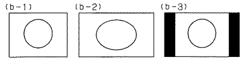
図5は、本発明の一実施例の映像信号再生装置の4:3フル画像の映像ソースの場合の、飛び越し走査映像用モニタに出画されるアスペクト比を説明する模式図である。同図(b−1)に示すように、4:3のモニタではアスペクト比が正しく表示されている。また、同図(b−2)に示すように、16:9のモニタではアスペクト比が正しく表示されず、横に引き延ばされた様に出画されるが、飛び越し走査映像用モニタでは、従来の飛び越し走査映像信号の標準的アスペクト比が4:3のため、4:3出力切り替え機能を装備しており、飛び越し走査映像用モニタに備える4:3出力切り替え機能を使用することによって、同図(b−3)に示すように、正しく4:3のアスペクト比で表示されるようになる。
【0057】
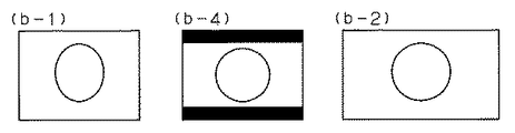
図6は、本発明の一実施例の映像信号再生装置の4:3レターボックス画像の映像ソースの場合の、飛び越し走査映像用モニタに出画されるアスペクト比を説明する模式図である。同図(b−1)に示すように、4:3のモニタではアスペクト比が正しく表示されている。また、同図(b−2)に示すように、16:9のモニタではアスペクト比が正しく表示されず、横に引き延ばされた様に出画されるが、飛び越し走査映像用モニタでは、従来の飛び越し走査映像信号の標準的アスペクト比が4:3のため、4:3レターボックス出力切り替え機能を装備しており、飛び越し走査映像用モニタに備える4:3出力切り替え機能を使用することによって、同図(b−3)に示すように、画面が上下に拡大され、正しく4:3のアスペクト比で画面一杯に表示されるようになる。また、映像ソースによっては、画像の下部の無画部に字幕情報が記録されている場合がある。この様なものには、同図(b−4)に示すように、表示位置が上方に移動される切替え機能も装備している。
【0058】
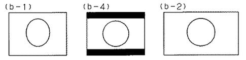
図7は、本発明の一実施例の映像信号再生装置の16:9画像の映像ソースの場合の、飛び越し走査映像用モニタに出画されるアスペクト比を説明する模式図である。同図(b−1)に示すように、4:3のモニタではそのままではアスペクト比が正しく表示されず、縦に引き延ばされた様に出画されるが、使用者が第1のアスペクト比設定手段13に接続されるモニタが16:9である事を設定する事によって、第1のアスペクト比変換回路6が動作し、アスペクト比変換され、同図(b−4)に示すように正しく表示される。なお、同図(b−2)に示すように16:9のモニタを用いる場合では、アスペクト比が正しく16:9のアスペクト比で表示される。
【0059】
即ち、飛び越し走査映像用モニタでは、4:3フル画像と、4:3レターボックス画像と、16:9画像との3種類の映像ソースと、4:3と16:9との2種類の映像用モニタの全ての組み合わせにおいても、従来技術において図16〜図18を参照して説明したと同様に、正しいアスペクト比で出画する事が可能である。
【0060】
一方、第1のアスペクト比変換回路6の出力は、順次走査映像信号変換回路9に入力される。順次走査映像信号変換回路9では、入力された飛び越し走査映像信号を順次走査映像信号に変換して出力する。
【0061】
図8は、本発明の一実施例の映像信号再生装置における第2のアスペクト比変換回路16の動作を説明する模式図である。
【0062】
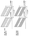
先ず、第2のアスペクト比変換回路6は、16:9の順次走査映像用モニタを想定し、4:3フル画像を水平方向に圧縮する水平アスペクト変換機能を持つ。即ち、図8[a]に示すように、4:3の素材を16:9のモニタにて、正しいアスペクト比で表示するために、入力される映像信号の4画素分の情報からフィルタ処理を行い、3画素分の情報を生成する。このような処理を全画面において行うと、画面全体が左右に圧縮され、アスペクト比的には正しく4:3の画面に変換できるが、左右に空白部分ができるので、その部分を黒画像とする。
【0063】
また、第2のアスペクト比変換回路6は、16:9の順次走査映像用モニタを想定し、図8[b]に示すように、4:3レターボックス画像を垂直方向に拡大する垂直アスペクト変換機能を持つ。即ち、4:3レターボックス画像を16:9のモニタにて、正しいアスペクト比で画面一杯に表示するために、入力される映像信号の3ライン素分の情報からフィルタ処理を行い、4ライン分の情報を生成する。このような処理を画面全体において行うと、画面全体が上下に拡大され、正しく16:9の画面に変換される。
【0064】
さらに、第2のアスペクト比変換回路16は、図8[c]に示すように、垂直方向に画像を拡大する際に、拡大後の画像の垂直中央位置が拡大前の垂直中央位置よりも予め設定されただけ上方に位置させる垂直表示位置移動機能を持つ。これは、図8[d]に示すように、垂直同期信号に対する画像信号位置を変化させる事で実現させる。
【0065】
これら3つのアスペクト比変換機能は、第2の制御回路12によって、それぞれ作動と非作動状態を選択する事ができる。両変換機能共に非作動の場合には、第2のアスペクト比変換回路16は、入力された映像信号のアスペクト比を変換をせずにそのまま出力する。
【0066】
図1において、使用者は、出画しようとする順次走査映像用モニタのアスペクト比が4:3であるか16:9であるかを、第1のアスペクト比設定手段12に設定し、出画しようとする順次走査映像用モニタのアスペクト比が4:3であるか16:9であるかと、更に、垂直表示位置の移動を行なうか否かを第2のアスペクト比設定手段14に設定する。一方、素材判別回路5は、映像ソースのアスペクト比が4:3フル画像なのか、4:3レターボックス画像なのか、16:9画像なのかの判別結果を第2の制御回路15に出力する。
【0067】
この第2の制御回路15は、次の5通りの指令を第2のアスペクト比変換回路16に対して出力する。
【0068】
(1)素材判別回路5が、映像ソースのアスペクト比が4:3フル画像、もしくは4:3レターボックス画像を示している場合で、かつ第2のアスペクト比設定手段14の出力が4:3の場合には、第2のアスペクト比変換回路16の水平アスペクト変換機能と垂直アスペクト変換機能と共に非作動とし、垂直表示位置移動機能も非作動とする。
【0069】
(2)素材判別回路5が、映像ソースのアスペクト比が4:3フル画像を示している場合で、かつ第2のアスペクト比設定手段14の出力が16:9の場合には、第2のアスペクト比変換回路16の水平アスペクト変換機能を作動とし、垂直アスペクト変換機能を非作動とする。
【0070】
(3)素材判別回路5が、映像ソースのアスペクト比が4:3レターボックス画像を示している場合で、かつ第2のアスペクト比設定手段14の出力が16:9の場合であり、かつ垂直位置移動が設定されていない場合には、第2のアスペクト比変換回路16の垂直アスペクト変換機能を作動とし、水平アスペクト変換機能を非作動とし、垂直表示位置移動機能を非作動とする。
【0071】
(4)素材判別回路5が、映像ソースのアスペクト比が4:3もしくは4:3レターボックス画像を示している場合で、かつ第2のアスペクト比設定手段14の出力が16:9であり、かつ垂直位置移動が設定されている場合には、第2のアスペクト比変換回路16の垂直アスペクト変換機能と垂直表示位置移動機能を作動とし、水平アスペクト変換機能を非作動とする。
【0072】
(5)素材判別回路5が、映像ソースのアスペクト比が16:9画像を示している場合には、第1のアスペクト比変換回路16の水平アスペクト比変換機能と垂直アスペクト変換機能と共に非作動とし、垂直アスペクト変換機能を非作動とする。
【0073】
色差コンバータ10は、順次走査映像信号を色差映像信号に変換し、順次走査映像出力端子11より、順次走査映像出力が順次走査映像用モニタ(図示は略す)に出力される。
【0074】
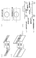
図9は、本発明の一実施例の映像信号再生装置における4:3フル画像の映像ソースの場合の、順次走査映像用モニタに出画されるアスペクト比を説明する模式図である。同図(c−1)に示すように、4:3のモニタではアスペクト比が正しく表示されている。ところが、同図(c−2)に示すように、16:9のモニタでは映像ソースそのままのアスペクト比では正しく表示されず、横に引き延ばされた様に出画される。前述したように、順次走査映像用の16:9のモニタは、ハイビジョン信号を想定したモニタで、ハイビジョン映像信号の標準的アスペクト比が16:9のため、4:3出力モードを装備しておらず、正しいアスペクト比で表示されない。しかしこの場合、使用者が、第1のアスペクト比設定手段13及び第2のアスペクト比設定手段14に接続されるモニタが16:9である事を設定する事によって、第2のアスペクト変換回路16の水平アスペクト比変換機能が作動し、同図(c−3)に示すように、正しいアスペクト比に変換された画像を表示する事ができる。
【0075】
図10は、本発明の一実施例の映像信号再生装置における4:3レターボックス画像の映像ソースの場合の、順次走査映像用モニタに出画されるアスペクト比を説明する模式図である。同図(c−1)に示すように、4:3のモニタではアスペクト比が正しく表示されている。ところが、同図(c−2)に示すように、16:9のモニタでは映像ソースそのままのアスペクト比では正しく表示されず、横に引き延ばされた様に出画される。上述したように、順次走査映像用の16:9のモニタは、ハイビジョン信号を想定したモニタで、ハイビジョン映像信号の標準的アスペクト比が16:9のため、4:3出力モードを装備しておらず、正しいアスペクト比で表示されない。しかしこの場合、使用者が、第1のアスペクト比設定手段13及び第2のアスペクト比設定手段14に接続されるモニタが16:9である事を設定する事によって、第2のアスペクト変換回路16の垂直アスペクト比変換機能が作動し、同図(c−4)に示すように、正しいアスペクト比で、かつ画面一杯に変換された画像を表示する事ができる。
【0076】
更に画像の下部無画部分に字幕情報が含まれる場合がある。この場合には図10(c−5)に示すように4:3の画面においては字幕の情報が完全に画面内に収まる様に字幕情報の垂直位置が決められている。これを垂直アスペクト比変換すると、同図(c−6)に示すように、字幕が完全に表示されないという問題が生じる。この場合には使用者は、第2のアスペクト比設定手段14に垂直表示位置の移動を指示すると、同図(c−7)に示すように、画像表示位置を予め設定された値のライン数だけ上方に移動し、垂直アスペクト比変換を行なった後でも字幕が画面から消えないような位置に表示位置を変える事ができる。
【0077】
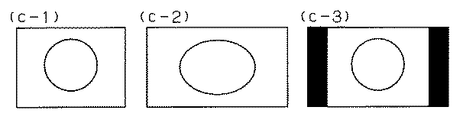
図11は、本発明の一実施例の映像信号再生装置における16:9画像の映像ソースの場合の、順次走査映像用モニタに出画されるアスペクト比を説明する模式図である。同図(c−1)に示すように、4:3のモニタではそのままではアスペクト比が正しく表示されず、縦に引き延ばされた様に出画されるが、使用者が第1のアスペクト比設定手段13および第2のアスペクト比設定手段14に接続されるモニタが4:3である事を設定する事によって、第1のアスペクト比変換回路6が動作し、アスペクト比変換されて同図(c−4)に示すように正しく表示される。また、同図(c−3)に示すように、16:9のモニタでは、アスペクト比が正しく16:9のアスペクト比で表示される。
【0078】
即ち、本発明の一実施例の映像信号再生装置では、順次走査映像用モニタにおいても、4:3フル画像、4:3レターボックス画像及び16:9画像の映像ソースと、4:3及び16:9の映像用モニタとの全ての組み合わせにおいて、正しいアスペクト比で出画する事ができ、かつ、4:3レターボックス画像において、画面下部無画部分に字幕が入った場合においても、字幕が見えなくなる事を防止する事が可能な映像信号再生装置が得られる。
【0079】
なお、本実施例では、映像ソースとして4:3フル画像及び4:3レターボックス画像及び16:9画像の3種類で説明したが、これは、ソースのアスペクト比の種類に応じて、第2のアスペクト比変換回路のアスペクト変換機能を変えれば、アスペクト比は限定されるものではなく、アスペクト比が3種類以上の場合においても応用ができるものである。
【0080】
また、図1において、符号4以降の各構成要因は、本実施例では回路等のハードウエアの形態としたが、これらはソフトウエアでの置き換えも可能なものである。
【0081】
また、第2のアスペクト比変換回路は、予め設定されたライン数だけ画像表示位置を上方に移動できる様にしたが、これは、設定値を可変にして、上方移動量を可変できるような構成にする事も可能である。
【0082】
更に、本実施例ではディスク媒体に記録された映像信号において説明を行ったが、これは、他のテープ媒体や、衛星放送、地上波放送等の映像信号を含んだ情報信号においても、同様に応用できるものである。
【0083】
【発明の効果】
以上のように本発明によれば、複数種の映像信号のアスペクト比の映像を、飛び越し走査映像用モニタ及び順次走査映像用モニタの何れに対しても、正しいアスペクト比で出画でき、かつ、4:3レターボックス画像において、画面下部無画部分に字幕が入った場合においても、字幕が見えなくなる事を防止する事が可能な映像信号処理装置が得られる。
【図面の簡単な説明】
【図1】本発明の一実施例の映像信号再生装置の構成を示すブロック図
【図2】同、ディスクに記録される映像信号の構造を示す模式図
【図3】同、映像信号のアスペクト比を示す模式図
【図4】同、第1のアスペクト比変換回路の動作を説明する模式図
【図5】同、4:3フル画像の映像ソースの場合の飛び越し走査映像用モニタに出画されるアスペクト比を説明する模式図
【図6】同、4:3レターボックス画像の映像ソースの場合の飛び越し走査映像用モニタに出画されるアスペクト比を説明する模式図
【図7】同、16:9画像の映像ソースの場合の飛び越し走査映像用モニタに出画されるアスペクト比を説明する模式図
【図8】同、第2のアスペクト比変換回路の動作を説明する模式図
【図9】同、4:3フル画像の映像ソースの場合の順次走査映像用モニタに出画されるアスペクト比を説明する模式図
【図10】同、4:3レターボックス画像の映像ソースの場合の順次走査映像用モニタに出画されるアスペクト比を説明する模式図
【図11】同、16:9画像の映像ソースの場合の順次走査映像用モニタに出画されるアスペクト比を説明する模式図
【図12】従来の映像信号再生装置の構成を示すブロック図
【図13】同、ディスクに記録される映像信号の構造を示す模式図
【図14】同、映像信号のアスペクト比を示す模式図
【図15】同、第1のアスペクト比変換回路の動作を説明する模式図
【図16】同、4:3フル画像の映像ソースの場合の飛び越し走査映像用モニタに出画されるアスペクト比を説明する模式図
【図17】同、4:3レターボックス画像の映像ソースの場合の飛び越し走査映像用モニタに出画されるアスペクト比を説明する模式図
【図18】同、16:9画像の映像ソースの場合の飛び越し走査映像用モニタに出画されるアスペクト比を説明する模式図
【図19】同、4:3フル画像の映像ソースの場合の順次走査映像用モニタに出画されるアスペクト比を説明する模式図
【図20】同、4:3レターボックス画像の映像ソースの場合の順次走査映像用モニタに出画されるアスペクト比を説明する模式図
【図21】同、16:9画像の映像ソースの場合の順次走査映像用モニタに出画されるアスペクト比を説明する模式図
【符号の説明】
1 ディスク
2 ピックアップ
3 ディスク回転装置
4 飛び越し走査映像信号再生回路
5 素材判別回路
6 第1のアスペクト比変換回路
7 エンコーダ
8 飛び越し走査映像出力端子
9 順次走査映像信号変換回路
10 色差コンバータ
11 順次走査映像出力端子
12 第1の制御回路
13 第1のアスペクト比設定手段
14 第2のアスペクト比設定手段
15 第2の制御回路
16 第2のアスペクト比変換回路[0001]
BACKGROUND OF THE INVENTION
The present invention sequentially records video signals by transferring various video information such as movie materials and video materials, such as recording on tape media or disk media, or satellite broadcasting or terrestrial broadcasting. output Video signal processing Relates to the device.
[0002]
[Prior art]
Conventionally, video output such as recording on a tape medium or a disk medium, or satellite broadcasting, cable broadcasting, or terrestrial broadcasting is usually output by interlaced scanning so that it can be reproduced by a television receiver. With the widespread use of compatible monitors, projectors, computer monitors, and the like, video signal reproduction apparatuses that convert these interlaced scanning video signals into sequential scanning signals are being introduced.
[0003]
FIG. 12 shows, as an example of the prior art related to the present invention, a video signal reproduction having a video signal and a discrimination flag for discriminating an aspect ratio of the video signal, and reproducing an information signal recorded on a disk-shaped disc. It is a block diagram which shows the structure of an apparatus. In FIG. 12,
[0004]
[0005]
[0006]
A
[0007]
The operation of the conventional video signal reproducing apparatus configured as described above will be described with reference to FIGS.
[0008]
FIG. 13 is a schematic diagram showing the structure of the video signal recorded on the
[0009]
FIG. 14 is a schematic diagram showing an aspect ratio of a video signal of a conventional video signal reproducing apparatus. As shown in FIG. 14A, the video signal of the video source recorded on the
[0010]
FIG. 14B shows the aspect ratio of the interlaced scanning video signal monitor. As shown in FIG. 14B, the interlaced scanning video signal monitor has an aspect ratio of 4: 3 shown in FIG. 14B-1 and 16: 9 shown in FIG. 14B-2. There are some aspect ratios.
[0011]
FIG. 14C shows the aspect ratio of the monitor for the progressive scanning video signal. As shown in FIG. 14 [c], the progressive scan video signal monitor has an aspect ratio of 4: 3 shown in FIG. 14 (c-1) and 16: 9 shown in FIG. 14 (c-2). There are some aspect ratios.
[0012]
The interlaced scanning video
[0013]
The user uses the first aspect ratio setting means 13 to set the aspect ratio of the monitor that is about to output the video signal. The
[0014]
FIG. 15 is a schematic diagram for explaining the operation of the first aspect
[0015]
In FIG. 12, the user uses the first aspect ratio setting means 13 to set whether the aspect ratio of the monitor to be displayed is 4: 3 or 16: 9. On the other hand, the
[0016]
The
[0017]
Next, the case where the video source in the conventional video signal reproduction apparatus corresponds to the angle of view of the interlaced scanning video monitor for each of the 4: 3 full image, the 4: 3 letterbox image and the 16: 9 image is shown in FIGS. 18 and the case corresponding to the angle of view of the monitor for continuous scanning video will be described below with reference to FIGS.
[0018]
FIG. 16 is a schematic diagram for explaining the aspect ratio output on the interlaced scanning video monitor in the case of the video source of 4: 3 full image in the conventional video signal reproducing apparatus. As shown in FIG. 16B-1, the aspect ratio is correctly displayed on the 4: 3 monitor. However, as shown in (b-2) in the figure, the 16: 9 monitor does not display the aspect ratio correctly, and the image is displayed as if it is stretched horizontally. On the other hand, the interlaced scanning video monitor has a 4: 3 output switching function because the standard aspect ratio of the conventional interlaced scanning video signal is 4: 3, and the interlaced scanning video monitor has a 4: 3 output. By using the switching function, an aspect ratio of 4: 3 is correctly displayed as shown in FIG.
[0019]
FIG. 17 is a schematic diagram for explaining the aspect ratio output on the interlaced scanning video monitor in the case of the video source of the 4: 3 letterbox image in the conventional video signal reproducing apparatus. As shown in FIG. 17B-1, the aspect ratio is correctly displayed on the 4: 3 monitor. On the other hand, as shown in (b-2) in the figure, the aspect ratio is not correctly displayed on the 16: 9 monitor, and the image is displayed as if it is stretched horizontally. On the other hand, since the standard aspect ratio of the conventional interlaced scanning video signal is 4: 3, the interlaced scanning video monitor is equipped with a 4: 3 letterbox video output switching function. By using the: 3 output switching function, the screen is enlarged vertically as shown in FIG. 3B-3, and the screen is correctly displayed with the aspect ratio of 16: 9. Also, depending on the video source, caption information may be recorded in a non-image area below the image. Such a device is also equipped with a switching function for moving the display position upward as shown in FIG.
[0020]
FIG. 18 is a schematic diagram for explaining the aspect ratio output on the interlaced scanning video monitor in the case of a 16: 9 video source in a conventional video signal reproducing apparatus. As shown in FIG. 18B-1, the aspect ratio is not correctly displayed on a 4: 3 monitor as it is, and the image is displayed as if it has been extended vertically. However, when the user sets that the monitor connected to the first aspect ratio setting means is 16: 9, the first aspect
[0021]
That is, in the conventional video signal reproducing apparatus, the interlaced scanning video monitor has three types of video sources, 4: 3 full image, 4: 3 letterbox image, and 16: 9 image, and 4: 3 and 16: 9. Even in all combinations of these two types of video monitors, it is possible to output images with the correct aspect ratio.
[0022]
On the other hand, the output of the first aspect
[0023]
FIG. 19 is a schematic diagram for explaining an aspect ratio output on a progressive scan video monitor in the case of a video source of 4: 3 full image in a conventional video signal reproduction apparatus. As shown in FIG. 19 (c-1), the aspect ratio is correctly displayed on the 4: 3 monitor. However, as shown in (c-2) in the figure, the 16: 9 monitor does not display the aspect ratio correctly, and the image is displayed as if it was stretched horizontally. Here, the 16: 9 monitor for progressively scanned video is a monitor that assumes a high-definition signal. Since the standard aspect ratio of a high-definition video signal is 16: 9, it does not have a 4: 3 output mode, and the correct aspect ratio. Is not displayed.
[0024]
FIG. 20 is a schematic diagram for explaining the aspect ratio output on the progressive scan video monitor in the case of the video source of the 4: 3 letterbox image in the conventional video signal reproduction apparatus. As shown in FIG. 20 (c-1), the aspect ratio is correctly displayed on the 4: 3 monitor. However, as shown in (c-2) in the figure, the 16: 9 monitor does not display the aspect ratio correctly, and the image is displayed as if it was stretched horizontally. As described above, the 16: 9 monitor for progressively scanned video is a monitor that assumes a high-definition signal, and since the standard aspect ratio of a high-definition video signal is 16: 9, it is equipped with a 4: 3 letterbox output mode. And the correct aspect ratio is not displayed.
[0025]
FIG. 21 is a schematic diagram for explaining an aspect ratio output on a progressive scan video monitor in the case of a 16: 9 video source in a conventional video signal reproduction apparatus. As shown in FIG. 21 (c-1), the aspect ratio is not correctly displayed on a 4: 3 monitor as it is, and the image is displayed as if it is stretched vertically. However, when the user sets that the monitor connected to the first aspect ratio setting means is 16: 9, the first aspect
[0026]
In other words, in the conventional video signal reproduction apparatus, the progressive scan video monitor outputs a 4: 3 full image and 4: 3 letterbox image video source in a correct aspect ratio when combined with a 16: 9 video monitor. I can't draw.
[0027]
[Problems to be solved by the invention]
As described above, in the conventional video signal reproducing apparatus, the progressive scan video monitor has a 4: 3 full image or 4: 3 letterbox image video source and a 16: 9 video monitor in combination. There is a problem that it is not possible to output images with the correct aspect ratio. From now on, all combinations of three types of video sources, 4: 3 full image, 4: 3 letterbox image and 16: 9 image, and two types of progressive scan video monitor, 4: 3 and 16: 9 A video signal that can be output with the correct aspect ratio and can prevent the subtitle from becoming invisible even when a subtitle is entered in the non-image area at the bottom of the screen in a 4: 3 letterbox image. The introduction of a playback device is required.
[0028]
The present invention solves the above-mentioned problems of the prior art, and it is possible to output images with a correct aspect ratio in all combinations of video sources having different aspect ratios and monitors having different aspect ratios, and 4: 3. In a letterbox image, a video signal that can prevent subtitles from becoming invisible even when subtitles are entered in the blank area at the bottom of the screen processing The purpose is to provide a device.
[0029]
[Means for Solving the Invention]
In order to solve this problem, the present invention A video signal reproducing apparatus capable of outputting a video signal to a first video monitor that can receive letterbox switching by inputting an interlaced scanning video signal and a second video monitor that cannot input letterbox switching by inputting a progressive scanning video signal. An input means for inputting a video signal; a video generation means for generating an interlaced scanning video signal or a progressive scanning video signal based on the input video signal; and the input video signal is a letterbox image. A determination means for determining whether or not there is a letterbox image when the input video signal is determined to be a letterbox image and an interlaced scanning video signal is input from the video generation means; On the other hand, when a scanning video signal is sequentially input from the video generation means, a letterbox switching process is performed and then output. Comprises a letterbox switching means, the output of the letterbox switching means, and output means capable of outputting on the video monitor to This is a video signal processing apparatus.
[0031]
DETAILED DESCRIPTION OF THE INVENTION
Of the present invention First The invention of A video signal reproducing apparatus capable of outputting a video signal to a first video monitor that can receive letterbox switching by inputting an interlaced scanning video signal and a second video monitor that cannot input letterbox switching by inputting a progressive scanning video signal. An input means for inputting a video signal; a video generation means for generating an interlaced scanning video signal or a progressive scanning video signal based on the input video signal; and the input video signal is a letterbox image. A determination means for determining whether or not there is a letterbox image when the input video signal is determined to be a letterbox image and an interlaced scanning video signal is input from the video generation means; On the other hand, when a scanning video signal is sequentially input from the video generation means, a letterbox switching process is performed and then output. Comprises a letterbox switching means, the output of the letterbox switching means, and output means capable of outputting on the video monitor to A video signal processing apparatus is provided.
[0033]
(Embodiment 1)
Hereinafter, with respect to an embodiment of the present invention, a case where an information signal including a video signal and a determination flag for determining an aspect ratio of the video signal reproduces a signal recorded on a disk-shaped disc will be described with reference to FIGS. Will be described.
[0034]
FIG. 1 is a block diagram showing the configuration of a video signal reproducing apparatus according to an embodiment of the present invention. In FIG. 1,
[0035]
[0036]
[0037]
[0038]
[0039]
A
[0040]
[0041]
The operation of the video signal reproducing apparatus of the present invention configured as described above will be further described.
[0042]
FIG. 2 is a schematic diagram showing the structure of a video signal recorded on the
[0043]
FIG. 3 is a schematic diagram showing the aspect ratio of the video signal of the video signal reproducing apparatus according to the embodiment of the present invention. Hereinafter, the aspect ratio of the video signal, the interlaced scanning video monitor and the progressive scanning video monitor will be described by taking the case of 4: 3 and 16: 9 as an example, but the aspect ratio of the present invention is limited to these two. It is not limited, and even if the aspect ratio is other, the idea is the same as the aspect ratio is changed, and the actions and effects are also the same. As shown in FIG. 3A, the video signal recorded on the
[0044]
FIG. 3B shows the aspect ratio of the interlaced scanning video signal monitor. As shown in FIG. 3B, the interlaced scanning video signal monitor has an aspect ratio of 4: 3 shown in FIG. 3B-1 and 16: 9 shown in FIG. 3B-2. There are some aspect ratios.
[0045]
FIG. 3C shows the aspect ratio of the monitor for progressively scanned video signals. As shown in FIG. 3 [c], the progressive scan video signal monitor has an aspect ratio of 4: 3 shown in FIG. 3 (c-1) and 16: 9 shown in FIG. 3 (c-2). There are some aspect ratios.
[0046]
The interlaced scanning video
[0047]
The user sets the aspect ratio of the interlaced scanning video monitor that is about to output the video signal by the first aspect ratio setting means 13. The
[0048]
FIG. 4 is a schematic diagram for explaining the operation of the first aspect
[0049]
The first aspect
[0050]
In FIG. 1, the user uses the first aspect
[0051]
The
[0052]
(1) When the
[0053]
(2) When the
[0054]
(3) When the aspect ratio of the video source indicates 16: 9 and the output of the first aspect ratio setting means 13 is 4: 3, the
[0055]
The
[0056]
FIG. 5 is a schematic diagram for explaining the aspect ratio displayed on the interlaced scanning video monitor in the case of the video source of 4: 3 full image of the video signal reproducing apparatus according to the embodiment of the present invention. As shown in FIG. 5B-1, the aspect ratio is correctly displayed on the 4: 3 monitor. In addition, as shown in FIG. 2B-2, the aspect ratio is not correctly displayed on the 16: 9 monitor, and the image is displayed as if it is stretched horizontally. Since the standard aspect ratio of the conventional interlaced scanning video signal is 4: 3, it is equipped with a 4: 3 output switching function. By using the 4: 3 output switching function provided in the interlaced scanning video monitor, As shown in the diagram (b-3), the image is correctly displayed with an aspect ratio of 4: 3.
[0057]
FIG. 6 is a schematic diagram for explaining the aspect ratio output on the interlaced scanning video monitor in the case of the video source of the 4: 3 letterbox image of the video signal reproducing apparatus according to the embodiment of the present invention. As shown in FIG. 5B-1, the aspect ratio is correctly displayed on the 4: 3 monitor. In addition, as shown in FIG. 2B-2, the aspect ratio is not correctly displayed on the 16: 9 monitor, and the image is displayed as if it is stretched horizontally. Since the standard aspect ratio of the conventional interlaced scanning video signal is 4: 3, a 4: 3 letterbox output switching function is provided, and by using the 4: 3 output switching function provided in the interlaced scanning video monitor. As shown in (b-3) of the figure, the screen is enlarged vertically so that the screen is correctly displayed with the aspect ratio of 4: 3. Also, depending on the video source, caption information may be recorded in a non-image area below the image. Such a device is also equipped with a switching function for moving the display position upward as shown in FIG.
[0058]
FIG. 7 is a schematic diagram for explaining the aspect ratio displayed on the interlaced scanning video monitor in the case of the video source of the 16: 9 image of the video signal reproducing apparatus according to the embodiment of the present invention. As shown in (b-1) in the figure, the aspect ratio is not correctly displayed on a 4: 3 monitor as it is, and the image is displayed as if it has been stretched vertically. By setting that the monitor connected to the ratio setting means 13 is 16: 9, the first aspect
[0059]
That is, in the interlaced scanning video monitor, three types of video sources of 4: 3 full image, 4: 3 letterbox image, and 16: 9 image, and two types of video of 4: 3 and 16: 9. Even in all combinations of monitors, it is possible to output an image with a correct aspect ratio, as described with reference to FIGS.
[0060]
On the other hand, the output of the first aspect
[0061]
FIG. 8 is a schematic diagram for explaining the operation of the second aspect
[0062]
First, the second aspect
[0063]
Further, the second aspect
[0064]
Further, a second aspect
[0065]
These three aspect ratio conversion functions can be selected between the activated and deactivated states by the
[0066]
In FIG. 1, the user sets in the first aspect ratio setting means 12 whether the aspect ratio of the progressive scan monitor to be output is 4: 3 or 16: 9. Whether the aspect ratio of the progressive scan monitor to be used is 4: 3 or 16: 9, and whether or not to move the vertical display position is set in the second aspect ratio setting means 14. On the other hand, the
[0067]
The
[0068]
(1) In the case where the
[0069]
(2) When the
[0070]
(3) The
[0071]
(4) The
[0072]
(5) When the aspect ratio of the video source indicates a 16: 9 image, the
[0073]
The
[0074]
FIG. 9 is a schematic diagram for explaining the aspect ratio displayed on the progressive scan video monitor in the case of a video source of 4: 3 full image in the video signal reproduction apparatus of one embodiment of the present invention. As shown in (c-1) in the figure, the aspect ratio is correctly displayed on the 4: 3 monitor. However, as shown in (c-2) in the figure, the 16: 9 monitor does not display correctly with the aspect ratio of the video source as it is, and the image is displayed as if it is stretched horizontally. As described above, the 16: 9 monitor for progressively scanned video is a monitor that assumes a high-definition signal, and since the standard aspect ratio of the high-definition video signal is 16: 9, a 4: 3 output mode is not provided. And the correct aspect ratio is not displayed. However, in this case, the user sets that the monitor connected to the first aspect ratio setting means 13 and the second aspect ratio setting means 14 is 16: 9, whereby the second
[0075]
FIG. 10 is a schematic diagram for explaining the aspect ratio output on the monitor for progressively scanned video in the case of the video source of the 4: 3 letterbox image in the video signal reproduction apparatus of one embodiment of the present invention. As shown in (c-1) in the figure, the aspect ratio is correctly displayed on the 4: 3 monitor. However, as shown in (c-2) in the figure, the 16: 9 monitor does not display correctly with the aspect ratio of the video source as it is, and the image is displayed as if it is stretched horizontally. As described above, the 16: 9 monitor for progressively scanned video is a monitor that assumes a high-definition signal, and since the standard aspect ratio of the high-definition video signal is 16: 9, a 4: 3 output mode is not provided. And the correct aspect ratio is not displayed. However, in this case, the user sets that the monitor connected to the first aspect ratio setting means 13 and the second aspect ratio setting means 14 is 16: 9, whereby the second
[0076]
Furthermore, subtitle information may be included in the lower non-image portion of the image. In this case, as shown in FIG. 10 (c-5), in the 4: 3 screen, the vertical position of the caption information is determined so that the caption information is completely within the screen. If this is converted into a vertical aspect ratio, the problem arises that the subtitles are not completely displayed as shown in FIG. In this case, when the user instructs the second aspect ratio setting means 14 to move the vertical display position, the image display position is set to a predetermined number of lines as shown in FIG. The display position can be changed to such a position that the subtitle does not disappear from the screen even after vertical aspect ratio conversion.
[0077]
FIG. 11 is a schematic diagram for explaining the aspect ratio output on the progressive scan video monitor in the case of the video source of 16: 9 image in the video signal reproduction apparatus of one embodiment of the present invention. As shown in (c-1) in the figure, the aspect ratio is not correctly displayed on a 4: 3 monitor as it is, and the image is displayed as if it has been stretched vertically. When the monitor connected to the ratio setting means 13 and the second aspect ratio setting means 14 is set to 4: 3, the first aspect
[0078]
That is, in the video signal reproducing apparatus according to the embodiment of the present invention, the video source of 4: 3 full image, 4: 3 letterbox image and 16: 9 image and 4: 3 and 16 are also used in the progressive scan video monitor. : In all combinations with the 9 video monitor, the correct aspect ratio can be displayed, and even in the case of 4: 3 letterbox images, subtitles appear in the non-image area at the bottom of the screen. A video signal reproducing apparatus capable of preventing the invisibility is obtained.
[0079]
In the present embodiment, the video source has been described with respect to three types of 4: 3 full image, 4: 3 letterbox image, and 16: 9 image. However, this depends on the type of the aspect ratio of the source. If the aspect ratio conversion function of this aspect ratio conversion circuit is changed, the aspect ratio is not limited, and can be applied even when the aspect ratio is three or more.
[0080]
In FIG. 1, the constituent elements after the
[0081]
In addition, the second aspect ratio conversion circuit can move the image display position upward by a preset number of lines, but this is configured so that the set value can be made variable and the upward movement amount can be made variable. It is also possible to make it.
[0082]
Furthermore, although the present embodiment has been described with reference to the video signal recorded on the disk medium, this also applies to other tape media and information signals including video signals such as satellite broadcast and terrestrial broadcast. It can be applied.
[0083]
【The invention's effect】
As described above, according to the present invention, it is possible to output images with aspect ratios of a plurality of types of video signals with a correct aspect ratio for both the interlaced scanning video monitor and the progressive scanning video monitor, and In a 4: 3 letterbox image, a video signal that can prevent subtitles from becoming invisible even when subtitles enter the blank area at the bottom of the screen. processing A device is obtained.
[Brief description of the drawings]
FIG. 1 is a block diagram showing a configuration of a video signal reproduction apparatus according to an embodiment of the present invention.
FIG. 2 is a schematic diagram showing the structure of a video signal recorded on the disc.
FIG. 3 is a schematic diagram showing the aspect ratio of the video signal.
FIG. 4 is a schematic diagram for explaining the operation of the first aspect ratio conversion circuit;
FIG. 5 is a schematic diagram for explaining an aspect ratio displayed on an interlaced scanning video monitor in the case of a 4: 3 full image video source;
FIG. 6 is a schematic diagram for explaining an aspect ratio displayed on an interlaced scanning video monitor in the case of a video source of a 4: 3 letterbox image;
FIG. 7 is a schematic diagram for explaining an aspect ratio output on a monitor for interlaced scanning video in the case of a video source of 16: 9 image.
FIG. 8 is a schematic diagram for explaining the operation of the second aspect ratio conversion circuit;
FIG. 9 is a schematic diagram for explaining an aspect ratio output on a progressive scan video monitor in the case of a 4: 3 full image video source;
FIG. 10 is a schematic diagram for explaining an aspect ratio displayed on a monitor for progressive scanning video in the case of a video source of 4: 3 letterbox image;
FIG. 11 is a schematic diagram for explaining an aspect ratio displayed on a progressive scan video monitor in the case of a 16: 9 video source;
FIG. 12 is a block diagram showing a configuration of a conventional video signal reproducing apparatus.
FIG. 13 is a schematic diagram showing the structure of a video signal recorded on the disc
FIG. 14 is a schematic diagram showing the aspect ratio of the video signal.
FIG. 15 is a schematic diagram for explaining the operation of the first aspect ratio conversion circuit;
FIG. 16 is a schematic diagram for explaining an aspect ratio displayed on an interlaced scanning video monitor in the case of a 4: 3 full image video source;
FIG. 17 is a schematic diagram for explaining an aspect ratio output on a monitor for interlaced scanning video in the case of a video source of 4: 3 letterbox image;
FIG. 18 is a schematic diagram for explaining the aspect ratio displayed on the interlaced scanning video monitor in the case of a 16: 9 video source;
FIG. 19 is a schematic diagram for explaining an aspect ratio output on a progressive scan video monitor in the case of a 4: 3 full image video source;
FIG. 20 is a schematic diagram for explaining an aspect ratio displayed on a progressive scan video monitor in the case of a video source of 4: 3 letterbox image;
FIG. 21 is a schematic diagram for explaining an aspect ratio output on a progressive scan video monitor in the case of a 16: 9 video source;
[Explanation of symbols]
1 disc
2 Pickup
3 Disc rotating device
4 Interlaced scanning video signal reproduction circuit
5 Material discrimination circuit
6 First aspect ratio conversion circuit
7 Encoder
8 Interlaced scanning video output terminal
9 Sequential scanning video signal conversion circuit
10 Color difference converter
11 Sequential scan video output terminal
12 First control circuit
13 First aspect ratio setting means
14 Second aspect ratio setting means
15 Second control circuit
16 Second aspect ratio conversion circuit
Claims (3)
映像信号を入力する入力手段と、
前記入力された映像信号に基づいて、飛び越し走査映像信号又は順次走査映像信号を生成する映像生成手段と、
前記入力された映像信号がレターボックス画像であるか否かを判断する判断手段と、
前記入力された映像信号がレターボックス画像であると判断した場合において、前記映像生成手段から飛び越し走査映像信号が入力された場合はレターボックス画像のまま出力する一方、前記映像生成手段から順次走査映像信号が入力された場合はレターボックス切替処理を施した上で出力するレターボックス切替手段と、
前記レターボックス切替手段の出力を、前記映像モニタに出力可能な出力手段と、
を備える映像信号処理装置。 A video signal processing apparatus capable of outputting a video signal to a first video monitor that can receive letterbox switching by inputting an interlaced scanning video signal and a second video monitor that cannot input letterbox switching by inputting a progressive scanning video signal. There,
An input means for inputting a video signal;
Video generation means for generating an interlaced scanning video signal or a progressive scanning video signal based on the input video signal;
Determining means for determining whether the input video signal is a letterbox image;
When it is determined that the input video signal is a letterbox image, when the interlaced scanning video signal is input from the video generation unit, the letterbox image is output as it is, while the video generation unit sequentially scans the video. Letterbox switching means for outputting after a letterbox switching process when a signal is input,
An output means capable of outputting the output of the letterbox switching means to the video monitor;
A video signal processing apparatus comprising:
Priority Applications (5)
| Application Number | Priority Date | Filing Date | Title |
|---|---|---|---|
| JP2000196084A JP4356202B2 (en) | 2000-06-29 | 2000-06-29 | Video signal processing device |
| EP01114824A EP1168834B1 (en) | 2000-06-29 | 2001-06-28 | Video signal reproduction apparatus |
| CA002351845A CA2351845C (en) | 2000-06-29 | 2001-06-28 | Video signal reproduction apparatus |
| US09/893,939 US7099570B2 (en) | 2000-06-29 | 2001-06-28 | Video signal reproduction apparatus |
| CN01119944.XA CN1344109A (en) | 2000-06-29 | 2001-06-29 | Ref reproduction equipment |
Applications Claiming Priority (1)
| Application Number | Priority Date | Filing Date | Title |
|---|---|---|---|
| JP2000196084A JP4356202B2 (en) | 2000-06-29 | 2000-06-29 | Video signal processing device |
Publications (3)
| Publication Number | Publication Date |
|---|---|
| JP2002016884A JP2002016884A (en) | 2002-01-18 |
| JP2002016884A5 JP2002016884A5 (en) | 2007-08-02 |
| JP4356202B2 true JP4356202B2 (en) | 2009-11-04 |
Family
ID=18694641
Family Applications (1)
| Application Number | Title | Priority Date | Filing Date |
|---|---|---|---|
| JP2000196084A Expired - Fee Related JP4356202B2 (en) | 2000-06-29 | 2000-06-29 | Video signal processing device |
Country Status (5)
| Country | Link |
|---|---|
| US (1) | US7099570B2 (en) |
| EP (1) | EP1168834B1 (en) |
| JP (1) | JP4356202B2 (en) |
| CN (1) | CN1344109A (en) |
| CA (1) | CA2351845C (en) |
Families Citing this family (17)
| Publication number | Priority date | Publication date | Assignee | Title |
|---|---|---|---|---|
| TWI261821B (en) * | 2002-12-27 | 2006-09-11 | Toshiba Corp | Information playback apparatus and information playback method |
| US20040213542A1 (en) * | 2003-04-22 | 2004-10-28 | Hiroshi Hamasaka | Apparatus and method to reproduce multimedia content for a multitude of resolution displays |
| WO2005001614A2 (en) * | 2003-06-02 | 2005-01-06 | Disney Enterprises, Inc. | System and method of dynamic interface placement based on aspect ratio |
| US20050179817A1 (en) * | 2004-01-14 | 2005-08-18 | Matsushita Electric Industrial Co., Ltd. | Video signal display unit |
| US7911536B2 (en) * | 2004-09-23 | 2011-03-22 | Intel Corporation | Screen filled display of digital video content |
| CN100518285C (en) * | 2004-09-29 | 2009-07-22 | Tcl王牌电子(深圳)有限公司 | Method for realizing TV set progressive scanning digital normalization |
| WO2006059779A1 (en) * | 2004-12-02 | 2006-06-08 | Sony Corporation | Encoding device and method, decoding device and method, program, recording medium, and data structure |
| TWI262725B (en) * | 2005-06-30 | 2006-09-21 | Cheertek Inc | Video decoding apparatus and digital audio and video display system capable of controlling presentation of subtitles and method thereof |
| US20080317120A1 (en) * | 2007-06-25 | 2008-12-25 | David Drezner | Method and System for MPEG2 Progressive/Interlace Type Detection |
| WO2010056737A2 (en) * | 2008-11-11 | 2010-05-20 | Mirna Therapeutics, Inc. | Methods and compositions involving mirnas in cancer stem cells |
| BRPI1005171A2 (en) | 2009-06-17 | 2019-07-02 | Panasonic Corp | information recording medium and playback device for reproduction of 3d images |
| US20110013888A1 (en) * | 2009-06-18 | 2011-01-20 | Taiji Sasaki | Information recording medium and playback device for playing back 3d images |
| JP2012044407A (en) * | 2010-08-18 | 2012-03-01 | Sony Corp | Image processing device, method, and program |
| US9043714B1 (en) * | 2011-01-07 | 2015-05-26 | Google Inc. | Adaptive user interface for widescreen devices |
| US20140092992A1 (en) | 2012-09-30 | 2014-04-03 | Microsoft Corporation | Supplemental enhancement information including confidence level and mixed content information |
| US9756282B2 (en) * | 2012-11-20 | 2017-09-05 | Sony Corporation | Method and apparatus for processing a video signal for display |
| KR102227088B1 (en) | 2014-08-11 | 2021-03-12 | 엘지전자 주식회사 | Device and control method for the device |
Family Cites Families (8)
| Publication number | Priority date | Publication date | Assignee | Title |
|---|---|---|---|---|
| JP2842913B2 (en) | 1990-01-24 | 1999-01-06 | 株式会社日立製作所 | Wide television signal processing circuit |
| US5673086A (en) * | 1990-10-05 | 1997-09-30 | Canon Kabushiki Kaisha | Image aspect ratio conversion processing apparatus |
| US5347318A (en) * | 1992-06-16 | 1994-09-13 | Canon Kabushiki Kaisha | Apparatus for processing video signals having different aspect ratios |
| JP3240697B2 (en) * | 1992-08-11 | 2001-12-17 | 松下電器産業株式会社 | Video magnifier |
| JP3282768B2 (en) | 1994-06-15 | 2002-05-20 | ソニー株式会社 | Television display method |
| JP3362538B2 (en) * | 1994-12-06 | 2003-01-07 | ソニー株式会社 | Video signal processing device and video signal reproducing device |
| US5745643A (en) * | 1995-04-06 | 1998-04-28 | Kabushiki Kaisha Toshiba | System for and method of reproducing playback data appropriately by the use of attribute information on the playback data |
| JP3953561B2 (en) * | 1996-10-15 | 2007-08-08 | 株式会社日立製作所 | Image signal format conversion signal processing method and circuit |
-
2000
- 2000-06-29 JP JP2000196084A patent/JP4356202B2/en not_active Expired - Fee Related
-
2001
- 2001-06-28 CA CA002351845A patent/CA2351845C/en not_active Expired - Fee Related
- 2001-06-28 US US09/893,939 patent/US7099570B2/en not_active Expired - Fee Related
- 2001-06-28 EP EP01114824A patent/EP1168834B1/en not_active Expired - Lifetime
- 2001-06-29 CN CN01119944.XA patent/CN1344109A/en active Pending
Also Published As
| Publication number | Publication date |
|---|---|
| EP1168834A2 (en) | 2002-01-02 |
| EP1168834B1 (en) | 2013-02-20 |
| JP2002016884A (en) | 2002-01-18 |
| US7099570B2 (en) | 2006-08-29 |
| US20020009295A1 (en) | 2002-01-24 |
| CN1344109A (en) | 2002-04-10 |
| CA2351845C (en) | 2008-09-30 |
| EP1168834A3 (en) | 2002-11-06 |
| CA2351845A1 (en) | 2001-12-29 |
Similar Documents
| Publication | Publication Date | Title |
|---|---|---|
| JP4356202B2 (en) | Video signal processing device | |
| JP2779212B2 (en) | Wide screen / standard screen television signal receiver | |
| US7536089B2 (en) | Image signal reproduction apparatus | |
| JP2001231016A (en) | Video signal reproducing device | |
| JPH07298160A (en) | Television receiver incorporating video cd reproducing device | |
| JP2651012B2 (en) | Television receiver | |
| JP3601336B2 (en) | Video signal playback device | |
| JP3646495B2 (en) | Video signal playback device | |
| JP4226127B2 (en) | Video signal playback device | |
| JP3601330B2 (en) | Video signal playback device | |
| JPH07307904A (en) | Dual screen television receiver | |
| JPH01194784A (en) | Television receiver | |
| KR100216913B1 (en) | Video level controlling apparatus by discriminating scanning mode of tv | |
| JPH0336473B2 (en) | ||
| JP2001223983A (en) | Device for converting video signal | |
| JP2677872B2 (en) | Magnetic recording / reproducing device | |
| JP2642601B2 (en) | Television receiver | |
| KR100240341B1 (en) | Video data reproducer of a video compact disc player | |
| JP4253058B2 (en) | Digital camera device | |
| JP2002271713A (en) | Television receiver | |
| JPH0282884A (en) | High picture quality television receiver | |
| JPH099172A (en) | Video signal processing unit | |
| JPH0265575A (en) | Display system for plural patterns of video reproducing device and video reproducing device displaying plural patterns | |
| JPH06311455A (en) | Television receiver | |
| JP2008172312A (en) | Video display device |
Legal Events
| Date | Code | Title | Description |
|---|---|---|---|
| A521 | Request for written amendment filed |
Free format text: JAPANESE INTERMEDIATE CODE: A523 Effective date: 20070614 |
|
| A621 | Written request for application examination |
Free format text: JAPANESE INTERMEDIATE CODE: A621 Effective date: 20070614 |
|
| RD01 | Notification of change of attorney |
Free format text: JAPANESE INTERMEDIATE CODE: A7421 Effective date: 20070712 |
|
| A977 | Report on retrieval |
Free format text: JAPANESE INTERMEDIATE CODE: A971007 Effective date: 20090213 |
|
| A131 | Notification of reasons for refusal |
Free format text: JAPANESE INTERMEDIATE CODE: A131 Effective date: 20090217 |
|
| A521 | Request for written amendment filed |
Free format text: JAPANESE INTERMEDIATE CODE: A523 Effective date: 20090420 |
|
| TRDD | Decision of grant or rejection written | ||
| A01 | Written decision to grant a patent or to grant a registration (utility model) |
Free format text: JAPANESE INTERMEDIATE CODE: A01 Effective date: 20090714 |
|
| A01 | Written decision to grant a patent or to grant a registration (utility model) |
Free format text: JAPANESE INTERMEDIATE CODE: A01 |
|
| A61 | First payment of annual fees (during grant procedure) |
Free format text: JAPANESE INTERMEDIATE CODE: A61 Effective date: 20090727 |
|
| FPAY | Renewal fee payment (event date is renewal date of database) |
Free format text: PAYMENT UNTIL: 20120814 Year of fee payment: 3 |
|
| FPAY | Renewal fee payment (event date is renewal date of database) |
Free format text: PAYMENT UNTIL: 20120814 Year of fee payment: 3 |
|
| FPAY | Renewal fee payment (event date is renewal date of database) |
Free format text: PAYMENT UNTIL: 20130814 Year of fee payment: 4 |
|
| LAPS | Cancellation because of no payment of annual fees |