CN1329682C - Ball valve with single piece packing - Google Patents
Ball valve with single piece packing Download PDFInfo
- Publication number
- CN1329682C CN1329682C CNB038058855A CN03805885A CN1329682C CN 1329682 C CN1329682 C CN 1329682C CN B038058855 A CNB038058855 A CN B038058855A CN 03805885 A CN03805885 A CN 03805885A CN 1329682 C CN1329682 C CN 1329682C
- Authority
- CN
- China
- Prior art keywords
- valve
- caulking piece
- valve according
- valve element
- piece
- Prior art date
- Legal status (The legal status is an assumption and is not a legal conclusion. Google has not performed a legal analysis and makes no representation as to the accuracy of the status listed.)
- Expired - Lifetime
Links
Images


Classifications
-
- F—MECHANICAL ENGINEERING; LIGHTING; HEATING; WEAPONS; BLASTING
- F16—ENGINEERING ELEMENTS AND UNITS; GENERAL MEASURES FOR PRODUCING AND MAINTAINING EFFECTIVE FUNCTIONING OF MACHINES OR INSTALLATIONS; THERMAL INSULATION IN GENERAL
- F16K—VALVES; TAPS; COCKS; ACTUATING-FLOATS; DEVICES FOR VENTING OR AERATING
- F16K5/00—Plug valves; Taps or cocks comprising only cut-off apparatus having at least one of the sealing faces shaped as a more or less complete surface of a solid of revolution, the opening and closing movement being predominantly rotary
- F16K5/06—Plug valves; Taps or cocks comprising only cut-off apparatus having at least one of the sealing faces shaped as a more or less complete surface of a solid of revolution, the opening and closing movement being predominantly rotary with plugs having spherical surfaces; Packings therefor
-
- F—MECHANICAL ENGINEERING; LIGHTING; HEATING; WEAPONS; BLASTING
- F16—ENGINEERING ELEMENTS AND UNITS; GENERAL MEASURES FOR PRODUCING AND MAINTAINING EFFECTIVE FUNCTIONING OF MACHINES OR INSTALLATIONS; THERMAL INSULATION IN GENERAL
- F16K—VALVES; TAPS; COCKS; ACTUATING-FLOATS; DEVICES FOR VENTING OR AERATING
- F16K27/00—Construction of housing; Use of materials therefor
- F16K27/06—Construction of housing; Use of materials therefor of taps or cocks
- F16K27/067—Construction of housing; Use of materials therefor of taps or cocks with spherical plugs
-
- F—MECHANICAL ENGINEERING; LIGHTING; HEATING; WEAPONS; BLASTING
- F16—ENGINEERING ELEMENTS AND UNITS; GENERAL MEASURES FOR PRODUCING AND MAINTAINING EFFECTIVE FUNCTIONING OF MACHINES OR INSTALLATIONS; THERMAL INSULATION IN GENERAL
- F16K—VALVES; TAPS; COCKS; ACTUATING-FLOATS; DEVICES FOR VENTING OR AERATING
- F16K11/00—Multiple-way valves, e.g. mixing valves; Pipe fittings incorporating such valves
- F16K11/02—Multiple-way valves, e.g. mixing valves; Pipe fittings incorporating such valves with all movable sealing faces moving as one unit
- F16K11/08—Multiple-way valves, e.g. mixing valves; Pipe fittings incorporating such valves with all movable sealing faces moving as one unit comprising only taps or cocks
- F16K11/087—Multiple-way valves, e.g. mixing valves; Pipe fittings incorporating such valves with all movable sealing faces moving as one unit comprising only taps or cocks with spherical plug
- F16K11/0873—Multiple-way valves, e.g. mixing valves; Pipe fittings incorporating such valves with all movable sealing faces moving as one unit comprising only taps or cocks with spherical plug the plug being only rotatable around one spindle
-
- F—MECHANICAL ENGINEERING; LIGHTING; HEATING; WEAPONS; BLASTING
- F16—ENGINEERING ELEMENTS AND UNITS; GENERAL MEASURES FOR PRODUCING AND MAINTAINING EFFECTIVE FUNCTIONING OF MACHINES OR INSTALLATIONS; THERMAL INSULATION IN GENERAL
- F16K—VALVES; TAPS; COCKS; ACTUATING-FLOATS; DEVICES FOR VENTING OR AERATING
- F16K5/00—Plug valves; Taps or cocks comprising only cut-off apparatus having at least one of the sealing faces shaped as a more or less complete surface of a solid of revolution, the opening and closing movement being predominantly rotary
- F16K5/06—Plug valves; Taps or cocks comprising only cut-off apparatus having at least one of the sealing faces shaped as a more or less complete surface of a solid of revolution, the opening and closing movement being predominantly rotary with plugs having spherical surfaces; Packings therefor
- F16K5/0626—Easy mounting or dismounting means
- F16K5/0636—Easy mounting or dismounting means the spherical plug being insertable from the top of the housing
-
- F—MECHANICAL ENGINEERING; LIGHTING; HEATING; WEAPONS; BLASTING
- F16—ENGINEERING ELEMENTS AND UNITS; GENERAL MEASURES FOR PRODUCING AND MAINTAINING EFFECTIVE FUNCTIONING OF MACHINES OR INSTALLATIONS; THERMAL INSULATION IN GENERAL
- F16K—VALVES; TAPS; COCKS; ACTUATING-FLOATS; DEVICES FOR VENTING OR AERATING
- F16K5/00—Plug valves; Taps or cocks comprising only cut-off apparatus having at least one of the sealing faces shaped as a more or less complete surface of a solid of revolution, the opening and closing movement being predominantly rotary
- F16K5/06—Plug valves; Taps or cocks comprising only cut-off apparatus having at least one of the sealing faces shaped as a more or less complete surface of a solid of revolution, the opening and closing movement being predominantly rotary with plugs having spherical surfaces; Packings therefor
- F16K5/0663—Packings
- F16K5/0668—Single packings
-
- F—MECHANICAL ENGINEERING; LIGHTING; HEATING; WEAPONS; BLASTING
- F16—ENGINEERING ELEMENTS AND UNITS; GENERAL MEASURES FOR PRODUCING AND MAINTAINING EFFECTIVE FUNCTIONING OF MACHINES OR INSTALLATIONS; THERMAL INSULATION IN GENERAL
- F16K—VALVES; TAPS; COCKS; ACTUATING-FLOATS; DEVICES FOR VENTING OR AERATING
- F16K5/00—Plug valves; Taps or cocks comprising only cut-off apparatus having at least one of the sealing faces shaped as a more or less complete surface of a solid of revolution, the opening and closing movement being predominantly rotary
- F16K5/06—Plug valves; Taps or cocks comprising only cut-off apparatus having at least one of the sealing faces shaped as a more or less complete surface of a solid of revolution, the opening and closing movement being predominantly rotary with plugs having spherical surfaces; Packings therefor
- F16K5/0663—Packings
- F16K5/0684—Packings on the plug
-
- F—MECHANICAL ENGINEERING; LIGHTING; HEATING; WEAPONS; BLASTING
- F16—ENGINEERING ELEMENTS AND UNITS; GENERAL MEASURES FOR PRODUCING AND MAINTAINING EFFECTIVE FUNCTIONING OF MACHINES OR INSTALLATIONS; THERMAL INSULATION IN GENERAL
- F16K—VALVES; TAPS; COCKS; ACTUATING-FLOATS; DEVICES FOR VENTING OR AERATING
- F16K5/00—Plug valves; Taps or cocks comprising only cut-off apparatus having at least one of the sealing faces shaped as a more or less complete surface of a solid of revolution, the opening and closing movement being predominantly rotary
- F16K5/06—Plug valves; Taps or cocks comprising only cut-off apparatus having at least one of the sealing faces shaped as a more or less complete surface of a solid of revolution, the opening and closing movement being predominantly rotary with plugs having spherical surfaces; Packings therefor
- F16K5/0663—Packings
- F16K5/0689—Packings between housing and plug
-
- F—MECHANICAL ENGINEERING; LIGHTING; HEATING; WEAPONS; BLASTING
- F16—ENGINEERING ELEMENTS AND UNITS; GENERAL MEASURES FOR PRODUCING AND MAINTAINING EFFECTIVE FUNCTIONING OF MACHINES OR INSTALLATIONS; THERMAL INSULATION IN GENERAL
- F16K—VALVES; TAPS; COCKS; ACTUATING-FLOATS; DEVICES FOR VENTING OR AERATING
- F16K5/00—Plug valves; Taps or cocks comprising only cut-off apparatus having at least one of the sealing faces shaped as a more or less complete surface of a solid of revolution, the opening and closing movement being predominantly rotary
- F16K5/06—Plug valves; Taps or cocks comprising only cut-off apparatus having at least one of the sealing faces shaped as a more or less complete surface of a solid of revolution, the opening and closing movement being predominantly rotary with plugs having spherical surfaces; Packings therefor
- F16K5/0663—Packings
- F16K5/0694—Spindle sealings
-
- Y—GENERAL TAGGING OF NEW TECHNOLOGICAL DEVELOPMENTS; GENERAL TAGGING OF CROSS-SECTIONAL TECHNOLOGIES SPANNING OVER SEVERAL SECTIONS OF THE IPC; TECHNICAL SUBJECTS COVERED BY FORMER USPC CROSS-REFERENCE ART COLLECTIONS [XRACs] AND DIGESTS
- Y10—TECHNICAL SUBJECTS COVERED BY FORMER USPC
- Y10T—TECHNICAL SUBJECTS COVERED BY FORMER US CLASSIFICATION
- Y10T137/00—Fluid handling
- Y10T137/0318—Processes
- Y10T137/0402—Cleaning, repairing, or assembling
- Y10T137/0491—Valve or valve element assembling, disassembling, or replacing
- Y10T137/0508—Ball valve or rotary ball valve
Landscapes
- Engineering & Computer Science (AREA)
- General Engineering & Computer Science (AREA)
- Mechanical Engineering (AREA)
- Taps Or Cocks (AREA)
- External Artificial Organs (AREA)
Abstract
A ball valve includes a valve element and a single piece packing that seals the valve element within a valve cavity. The single piece packing is installed over the valve element at room temperature or may be molded thereon. The valve element may include a flow control element such as a ball and upper and lower trunnions. The various dimensions of the valve element and packing are selected to facilitate room temperature assembly and to substantially reduce the volume of packing material, thereby improving the performance of the valve over wider temperature ranges and pressure ratings.
Description
The application requires to enjoy in the preference of the No.PCT/US2003/01351 of international patent application formerly that is entitled as " ball valve with single piece packing " that submitted on January 17th, 2003, and this international patent application requires to enjoy in the preference of the U.S. Provisional Patent Application No.60/349629 that is entitled as " ball valve with single piece packing " that submitted on January 18th, 2002, and whole disclosures of this application are incorporated herein fully by reference.
Technical field
The present invention relates generally to ball valve.More particularly, the present invention relates to a kind of ball valve design of novelty and the notion of caulking piece, it can improve the performance of valve under higher and lower nominal operation temperature and thermal cycle.
Background technique
Ball valve is well-known in the art, authorize people such as Corbin and by the U.S. Patent No. 4685488 that assignee of the present invention had in introduced a kind ofly at commercial extremely successful ball valve, whole disclosures of this patent are incorporated herein fully by reference.
Under specified pressure, use polymer to be limited in usually in its high temperature and low-temperature working scope specified or regulation as the ball valve of the material of spherical caulking piece.This is because gasket can expand with the speed different with other valve element of usually being made by stainless steel and shrink.Under higher temperature, gasket deliquescing and be tending towards flowing or creep, and the damage of permanent deformation or alternate manner may take place during the valve events under the high-temperature.The damage of this caulking piece may cause leaking, and it is especially true to get back to ambient temperature following time at valve.Under colder temperature, gasket hardening and rigidity increase, and in some cases because caulking piece can produce contraction at a lower temperature, so the Sealing Stress on the caulking piece may reduce.This stress loss may produce leakage at low temperatures.Though has known and in ball valve, to have introduced the nominal operation temperature range of dynamic load filling technique, yet whole improvement still is subject to the temperature response characteristics of gasket self with the raising ball valve.
Need a kind of ball valve with polymer-type ball gasket, it has the nominal operation temperature range and the temperature Cycle of raising under rated pressure always.
Summary of the invention
The present invention proposes a kind of ball-cock device, wherein can in certain temperature range, single piece packing be installed on the valve element, the feasible mechanical property that can not change gasket basically.The invention allows for assembly method.The invention allows for a kind of valve element and caulking piece, wherein can select different sizes so that by such as volume that reduces gasket and the nominal operation temperature range and the cycle life that after being installed to caulking piece on the valve, on caulking piece, provide more uniform load distribution to improve valve.All aspects of of the present invention all optionally are applied in the multi-part type caulking piece.In addition, the present invention proposes a kind of spheroid and trunnion design, it makes ball valve element axially unsteady or mobile in the time of can expanding under temperature variation at the caulking piece of valve element and shrink.Another aspect of the present invention relates to the use of the dynamic load on the caulking piece that is applied to the valve element that combines with the axial float of valve element.
According to the invention provides a kind of valve, it comprises: the valve body that wherein has valve pocket; The valve element, it can control flowing by valve around the rotational position of axis according to the valve element; And be sealed in single piece packing in the valve pocket round the valve element and with the valve element; Wherein, the valve element comprises spheroid and adjacent upper and lower gudgeon; Following gudgeon is the lower end of extend past caulking piece axially; The size of valve pocket is made for can closely hold the valve element, allows the valve element to move axially with the temperature effect on the compensation caulking piece simultaneously.
Following detailed description by reading a plurality of embodiment of the present invention and modification thereof and with reference to the accompanying drawings can easier and more completely be understood these and other aspect and advantage of the present invention.
Description of drawings
Fig. 1 is the shaft section figure (valve is shown as and is in open mode) such as grade that has comprised the ball valve of All aspects of of the present invention;
Fig. 2 is the vertical front side sectional view of valve shown in Figure 1;
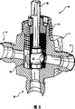
Fig. 3 has shown the front view according to valve element of the present invention;
Fig. 4 be used for single piece packing embodiment illustrated in fig. 1 and support ring etc. the axle decomposition view;
Fig. 4 A is the partial sectional view of caulking piece shown in Figure 4;
Fig. 5 is a broken away view that waits of another embodiment of the present invention, and it has the 3rd flowing ports of increase; With
Fig. 6 has been to use the broken away view such as axle such as grade of another embodiment of the present invention of aspheric ball valve element.
Embodiment
Referring to accompanying drawing, the present invention proposes a kind of ball valve design that can under rated pressure, improve the temperature performance rating value.This improved temperature performance comprises the temperature range of higher and lower specified or regulation, and thermal cycle.Introduce the present invention with reference to concrete ball valve design here, yet those skilled in the art will readily understand, All aspects of of the present invention can be incorporated in the different ball valve structures.In addition, though the representative embodiment of this paper has comprised some different aspects of the present invention, yet can not understand the present invention with restrictive meaning.On the contrary, some or all aspect and features of the present invention all can be incorporated in the ball valve design individually or in the mode of various combinations or sub-portfolio, and still belong in the scope and spirit of setting forth in claims of the present invention.And, though introduced a plurality of alternatives in this article, yet these limits of describing not all alternative enumerate, these alternatives those skilled in the art is conspicuous after having understanded present disclosure.Whether no matter described clearly in this article, the present invention all can visualize the alternative that belongs in the claims scope.Though representative embodiment has shown the caulking piece of a kind of integrated type or single-piece, yet All aspects of of the present invention also all can be used in the multi-part type caulking piece.
All aspects of of the present invention are shown among the figure, and it is presented as ball valve 10, and this ball valve 10 has valve body 12, and it has the suitable edge joint 14 and 16 that is used for valve 10 is installed in fluid circuit.Corresponding hole 18a and 18b extend out from each edge joint 14,16 and pass valve body 12, and the central spheroid that is formed between these two holes that leads in the valve body 12 holds in the valve pocket 20.Valve component element 22 partly is arranged in the valve pocket 20 and therefrom extends out.Valve component element 22 comprises flow control spheroid 24, and its actuating rod 26 best and valve is processed into an integral body, but this is not necessary.Spheroid 24 has central fluid channel or the hole 27 that is processed to therefrom pass, and has formed opening or bar hole 27a and the 27b that aligns with the hole 18a and the 18b of valve body, thereby allows fluid to flow between them when valve is in open position shown in the figure.Make hole 27a when bar 26 and spheroid 24 are rotated to, 27b not with valve body hole 18a, during the 18b positions aligning, valve is in the closed position, the mobile of fluid is blocked.For example, turn 90 degrees by spheroid 24 is revolved (1/4 circle) but just cut-off valve 10.
What valve rod 26 extended through valve body 12 selectively has an externally threaded integral bonnet 12a.Bar 26 also can comprise and is used for manually operated handle (not shown), perhaps can be connected on valve actuating mechanism (not shown) such as electronic or pneumatic or the hydraulic actuator.Bar 26 causes spheroid 24 to rotate in valve pocket 20 around the rotation of its longitudinal axis X, thereby opens and closes valve.
Valve rod 26 also comprises gudgeon 28 and following gudgeon 30.Last gudgeon 28 can help valve element 22 aliging in valve pocket 20 to be connected with axle journal with following gudgeon 30 with valve caulking piece 32.According to an aspect of the present invention, at room temperature between the outer surface of the internal surface of caulking piece 32 and spheroid 24 and gudgeon 28,30, formed and cooperated very closely or interference fit.In addition, after valve component element 22 being installed and is pressed in the valve pocket 20 fully, the spherical part around spheroid and hold the outer surface of the caulking piece 32 in the part of gudgeon and the surface in chamber 20 between at room temperature exist interference fit.On these diameters and interference fit gudgeon are caulking piece 32 and bar surface 24, provide bigger and more equally distributed seal action power or pressure between 28 and 30 (being the surface of spheroid and gudgeon), and required dynamic load is littler than the valve of prior art on the caulking piece 32.
According to an aspect of the present invention, valve caulking piece 32 bar surface 24,28 and 30 and valve body 12 between liquid-tight seal is provided.In this embodiment, caulking piece 32 is fixed with respect to the rotation of valve rod 26 and spheroid 24 during the action of valve.In its preferred but not exclusive form, referring to Fig. 4, caulking piece 32 is a single piece packing, this means that caulking piece is a monomer structure, and itself and valve rod 26 are press-fitted and are assembled into valve component element 22, this valve component element 22 are installed in the valve body 12 afterwards again.Caulking piece 32 preferably but not necessarily made by perfluoro alkoxy (PFA) material and can be made by traditional machining or molding process.Other suitable material that is used for caulking piece 32 includes but not limited to that the variant of ultra-high molecular weight polyethylene, PTFE (teflon) and PTFE is as PTFE, the polyether-ether-ketone (PEEK) of being with packing, PFA or the fluorinated ethylene propylene copolymer of being with packing.In some applications, also wish the single piece packing molded on gudgeon and spheroid.
For the opening (as opening 52a and the 52d of Fig. 4) that when valve 10 is shown in an open position, is used for making fluid to flow, the support ring 42,44 that is inserted into through being slidingly matched in these openings can be set.Support ring 42,44 comprises through hole 42a and 44a respectively, and it is used for allowing when valve 10 is shown in an open position fluid therefrom to flow through.Support ring 42,44 can support caulking piece 32 in the zone of opening 52, be squeezed among passage 27 or port 27a and the 27b to prevent caulking piece.In order to strengthen this effect, support ring 42,44 can be provided with inner plane 62, and it roughly aligns with the X-axis line when being installed to support ring in the caulking piece.The rigidity of support ring has been improved on these planes, thereby has improved their supports to gasket under the load.
Each opening 52a-d all can comprise the flange 64 of inner circumferential protrusions.These flanges can prevent that support ring 42,44 from touching the outer surface of spheroid 24 unintentionally when bar 26 rotations.
When not needing to use a plurality of openings 52 (for example opening 52c or 52b) in the specific valve arrangement (for example only needing two openings 52 at Twoway valves), all available suitable disc of these obsolete openings or stopper 60 are blocked (Fig. 4).Each disc 60 all is slidingly matched in its corresponding opening 52.Disc 60 has supported caulking piece 32, make its can cold flow extruding and creep in the zone of passage 27.
Disc 60 (and support ring 42,44) can make by any suitable material such as stainless steel, preferred but might not be crooked or form other shape, its outer surface is conformed to the external frame of caulking piece 32, and its internal surface conforms to the interior profile of caulking piece 32 and (should be noted that in the embodiment shown, caulking piece 32 has columniform outer surface profile, and its inner surface profile includes spherical part and cylindrical part).Disc 60 is placed on the inward flange 64 of respective openings 52, thereby can not touch the surface of spheroid.
For being installed on the valve element 22, caulking piece 32 (is different from molded technology), incompatible caulking piece 32 and all-in-one-piece spheroid and bar are assembled together by being press-fitted, caulking piece 32 buckles or slide into appropriate location on the bar 26, and cross gudgeon 28 or the down outer surface or the diameter of gudgeon 30 and spheroid 24, wherein the diameter of spheroid must be greater than the diameter of gudgeon 28,30.If the volume of caulking piece 32 is excessive, so at room temperature caulking piece 32 will be too firm and not flexible, so that can not slide into position shown in the figure on the spheroid 24.According to an aspect of the present invention, valve element 22 is machined to makes the diameter D1 of spheroid 24, any or all in the D3 (see figure 3) only slightly greater than the respective diameters D2 of gudgeon 28,30.According to selected valve design, the diameter D2 of gudgeon, D3 can be identical or different.
In the ball valve of prior art, the diameter of gudgeon and spheroid is than (D2/D1 or D3/D1) 0.3-0.65 normally.According to the present invention, this ratio should be preferably about 0.7 to about 0.9, preferably about 0.70 to about 0.76.This obviously higher ratio (diameter of spheroid has increased gudgeon relatively) has reduced the quality volume of caulking piece 32 significantly, and this is because reduce in the gap between gudgeon and the valve pocket 20.The minimizing of the quality volume of caulking piece 32 also makes caulking piece 32 at room temperature more pliable and tougher, thereby allows at room temperature caulking piece 32 by being clasped or press fit is installed on the valve element 22.Because spheroid 24 just is slightly larger than gudgeon 28,30, therefore before being installed to valve element 22 in the valve body 12, can at room temperature easily more pliable and tougher caulking piece 32 be installed on the valve element 22.This has just greatly simplified assembly technology, thereby has reduced installation time and cost.
Here used term " room temperature " only is meant the temperature range that gasket can notable change aspect its performance such as elastic characteristic.Exemplary but the nonessential scope that is used for the room temperature assembling is about 65-100 .In other words, " room temperature " is meant that caulking piece remains essentially in and can significantly do not change its mechanical property such as its flexible temperature range under its normal condition.
Should be noted in the discussion above that in this another technology that is used for single piece packing is located on valve rod/spheroid/gudgeon element is with the caulking piece molded in position.In other words, utilize traditional molding technique that caulking piece directly is molded on the bar.Molded technology has been eliminated the installation step that caulking piece 32 is slided into the appropriate position on the bar.Yet, other advantage of the present invention and aspect that the single piece packing of in position locating by molded also can realization can cause caulking piece quality volume to reduce.
Then introduce the structure of valve 10 below, be provided with caulking piece gland 34 in the axial vicinity of the upper surface of valve caulking piece 32.This caulking piece gland 34 for example can be made by stainless steel, and it is with helping to suppress caulking piece 32 when temperature raises, also with the thrust washer of making caulking piece 32 is provided dynamic load.Diametric clearance between the diameter of the diametric clearance between the outer diameter D 2 of the internal diameter of gland 34 and last gudgeon 28 and the external diameter of gland 34 and valve pocket 20 all is controlled, so that make gland 34 can suppress caulking piece 32, thereby reduce or reduce creep or extruding when temperature raises, and with the thrust washer of work to caulking piece 32 loadings.A plurality of disc springs 36 or other suitable loaded member are axially piled up (with reference to the longitudinal axis X of bar 26), and are pressed on the gland 34.36 pairs of glands 34 of load elements and caulking piece 32 apply dynamic load, thereby can keep the abundant seal compression to caulking piece 32 under higher and lower temperature." dynamic load " refers to be higher or lower than when working under room temperature or the ambient temperature when valve, and load elements 36 is sustainably to gland 34 and caulking piece 32 imposed load power.By just compressible loads part 36 and hold it in suitable position of threaded packing bolt 38, this bolt 38 holds on the 12a of extension by top or the bar that screw thread is installed in valve body 12.
Following gudgeon 30 axially extends in the counterbore 40 that is formed in the valve body 12 under the 32a of the bottom of caulking piece 32.Between the diameter of following gudgeon 30 and counterbore 40, preferably has Spielpassung closely.This Spielpassung closely helps to suppress the creep or the extruding of caulking piece 32 bottoms, keep the contact stress between caulking piece 32 and the spheroid 24, and keep the contact stress between the rough surface (for example becoming coarse) of caulking piece 32 and valve pocket 20, rotate in valve body 12 at caulking piece 32 during the action of valve preventing by sand blast.The inhibition of caulking piece bottom 32a has been reduced the stress relaxation of caulking piece under non-ambient temperature and low especially temperature.The inhibition feature of the upper and lower of caulking piece allows axially motion of valve element 22, with expansion and the contraction of compensation caulking piece 32 in thermal cycle.
When valve 10 was in the position of opening fully, the opening 52a of caulking piece 32 and 52d alignd with one heart with the bar hole 27a and the 27b of ball fluid passageway respectively.At hole 27a and 27b place, stop ring or support ring 42,44 and disc 60 are positioned among the opening 52a-d of caulking piece 32 respectively and help to suppress caulking piece 32, are squeezed in the passage 27 and hole 27a and 27b of spheroid to prevent gasket.
Valve assembles as described below.In due course support ring 42,44 and disc 60 are inserted among the opening 52a-d of caulking piece 32.Like this, support ring and disc also can help to support caulking piece 32 during assembly technology.As described above caulking piece 32 is installed on the valve rod 26 then.To comprise that spheroid/bar 24/26, single piece packing 32 and support ring 42,44 (and if needed with the disc 60 that uses) are installed in the valve pocket 20 of valve body 12 at interior valve component element 22.When being inserted into assembly 22 in the valve body, can use proper implements to align and compression assembly 22.Gland 34 and loading element 36 can be installed on the caulking piece 32 before being installed to the valve component element in the valve body 12, or installed after the valve component element being installed in the valve body.Packing bolt 38 is screwed among the extension 12a of valve rod, then so that finish assembling.Bolt 38 can tighten to suitable moment of torsion or certain number of turns, so that act on required load on caulking piece 32.
According to a further aspect in the invention, the amount that reduces the volume of caulking piece or constitute the material of single piece packing can realize by the ratio (H/D4) that reduces caulking piece height (among Fig. 3 " H ") and caulking piece outer diameter D 4.In Fig. 3, the caulking piece height is designated as " H ".This just can be by reducing the gasket that is used for caulking piece 32 with the similar mode of the increase gudgeon mentioned above and the ratio of sphere diameter.Because only need a spot of gasket just can seal this valve fully, therefore the negative effect that causes because of temperature variation under high temperature and low temperature and thermal cycle all reduces.In the ball valve of typical prior art, the ratio of caulking piece height and caulking piece external diameter is in 0.9 to 1.1 the scope, and in the present invention, and the ratio of caulking piece height and caulking piece external diameter is about 0.75 to about 0.85, and optimum value is about 0.8.For the ball valve of the ratio that adopts traditional trunnion diameter and sphere diameter or caulking piece height and the prior art of the ratio of caulking piece external diameter, the whole structure of controlling these ratios is that the caulking piece volume has been reduced about 15% to about 50%, thereby the thermal characteristics that significantly improves is provided.
Should be noted in the discussion above that each ratio described here can change according to the size of valve, this is very important.For example, the exemplary ratio range that is used for D3/D1 here is to design for the ball valve element that is used for 1/4 inch pipe-line system.According to the present invention, but reduced value D2/D1 or D3/D1 select, make it can promote at room temperature caulking piece to be assembled on the valve element.In addition, also can select, thereby make its volume that can reduce caulking piece and improve thermal characteristics the ratio of H/D4.
The caulking piece 32 that is contemplated that enlarges gudgeon provides the more effective dynamic load that can be delivered in the caulking piece bottom.In the small trunnion design of prior art, most of normal load is born by the spheroid part 24 of valve rod.Comparatively speaking, the present invention who has the trunnion diameter of expansion is concentrated into dynamic load towards caulking piece and loads, and with this load and caused tamp the bottom that Sealing Stress is delivered to caulking piece, distribute evenly many and much effective loading tension thereby provide, so that keep sealing.
The claimant has been found that thermal expansion or excessive load that support ring 42,44 in some cases may be after caulking piece uses be produced in because of assembly process are vertically crushed.According to the present invention,, just can realize resistance on the internal diameter of support ring 42,44 at the raising of vertical fragmentation by vertical plane 62 is provided.Should vertically align with the center line (X-axis among the figure) of valve 10 in this plane.These planes also can be used as positioning guiding structure, to guarantee support ring correct orientation during installation.On disc 60, can use groove or other suitable mark 63, to guarantee the correct orientation of disc 60.
In order in action (spheroid rotation) process of valve, to clamp gasket in the edge of anti-stopping bar hole 27a and 27b, can be at each bar hole 27a, around the 27b flanging (edge break) is set, this is preferred but nonessential.
According to a further aspect in the invention, should be noted in the discussion above that bar 26 and integral ball 24 in the axial direction (along X-axis) be not subjected to the constraint of dynamic load disc spring 36 and below counterbore 40.Therefore, bar 26 can cause caulking piece 32 to produce under the temperature variation that expands and shrink in meeting freely moving.This helps to keep unanimity and effective load on caulking piece 32.
Fig. 5 has shown another embodiment who is combined with valve 68 of the present invention.In this example, in spheroid 24, be formed with bottom port (not shown) with the 3rd joint 70 fluid communication.Identical in other element of valve and the foregoing description.
Introduced the present invention hereinbefore with reference to preferred embodiment.By reading and understanding this specification, other people can visualize many modifications and variations.As long as fall in the scope of claims or its equivalent, all such modifications and variation all should be included among the present invention.
Claims (25)
1. valve comprises:
The valve body that wherein has valve pocket;
The valve element, it can control flowing by described valve around the rotational position of axis according to described valve element; With
Be sealed in single piece packing in the described valve pocket round described valve element and with described valve element; Wherein, described valve element comprises spheroid and adjacent upper and lower gudgeon; Described gudgeon down is the lower end of the described caulking piece of extend past axially; The size of described valve pocket is made for can closely hold described valve element, allows described valve element to move axially to compensate the temperature effect on the described caulking piece simultaneously.
2. valve according to claim 1 is characterized in that described caulking piece is a single piece packing, and its size is made for and is suitable for being installed in room temperature range on the described valve element.
3. valve according to claim 2 is characterized in that, described room temperature range is 65-100 .
4. valve according to claim 2 is characterized in that, described caulking piece has the outer surface of the substantial cylindrical that is limited by height H and outer diameter D 4, and it is 0.75 to 0.85 ratio H/D4 that described caulking piece has.
5. valve according to claim 4 is characterized in that, described ratio H/D4 is 0.8.
6. valve according to claim 1 is characterized in that described spheroid has outer diameter D 1, in the described gudgeon one of them has outer diameter D 3 at least; It is 0.7 to 0.9 ratio D3/D1 that described valve element has.
7. valve according to claim 6 is characterized in that, described ratio D3/D1 is 0.8.
8. valve according to claim 2 is characterized in that, described caulking piece has the outer surface of the substantial cylindrical that is limited by height H and outer diameter D 4, and it is 0.75 to 0.85 ratio H/D4 that described caulking piece has; Described spheroid has outer diameter D 1, in the described gudgeon one of them has outer diameter D 3 at least; It is 0.7 to 0.9 ratio D3/D1 that described valve element has.
9. valve according to claim 8 is characterized in that, described ratio H/D4 is 0.8, and described ratio D3/D1 is 0.8.
10. valve according to claim 1 is characterized in that described caulking piece comprises polymer.
11. valve according to claim 10 is characterized in that, described polymer is selected from polytetrafluoroethylene PTFE, polyethylene, polyether-ether-ketone PEEK and fluorinated ethylene propylene copolymer.
12. valve according to claim 1 is characterized in that, described valve element comprises aspheric flow control member.
13. valve according to claim 2, it is characterized in that described caulking piece has internal surface, before being loaded into described caulking piece in the described valve body, when described caulking piece being installed on the described valve element, described internal surface can form interference fit with described valve element.
14. valve according to claim 2, it is characterized in that, before being loaded into described caulking piece in the described valve pocket, when described caulking piece being installed on the described valve element and being inserted in the described valve pocket, described caulking piece can form interference fit with described valve pocket.
15. valve according to claim 1 is characterized in that, described caulking piece comprises the polymer of the PTFE, polyethylene, polyether-ether-ketone PEEK and the fluorinated ethylene propylene copolymer that are selected from PFA, the PFA that is with packing, polytetrafluoroethylene PTFE, band packing.
16. valve according to claim 1 is characterized in that, the size of described caulking piece is made for and can be installed on the described valve element being lower than under the temperature that described caulking piece can produce distortion.
17. valve according to claim 16 is characterized in that, described temperature is a room temperature.
18. valve according to claim 16 is characterized in that, described caulking piece is a single piece packing.
19. valve according to claim 16 is characterized in that, described caulking piece molded is on described valve element.
20. valve according to claim 1 is characterized in that, described caulking piece is the multi-part type caulking piece.
21. valve according to claim 1 is characterized in that, described spheroid has outer diameter D 1, in the described gudgeon one of them has outer diameter D 3 at least; Described valve element has the ratio D3/D1 that can be convenient at room temperature described caulking piece is installed on the described valve element.
22. valve according to claim 1 is characterized in that, described valve pocket comprises the hole that diameter reduces, and it has held described gudgeon down and can prevent that the gasket creep is to the described below of gudgeon down.
23. valve according to claim 1 is characterized in that, described caulking piece affords dynamic load.
24. valve according to claim 1 is characterized in that, described caulking piece comprises thermoplastic polymer.
25. valve according to claim 1 is characterized in that, described polymer comprises PTFE.
Applications Claiming Priority (2)
| Application Number | Priority Date | Filing Date | Title |
|---|---|---|---|
| US34962902P | 2002-01-18 | 2002-01-18 | |
| US60/349,629 | 2002-01-18 |
Related Child Applications (1)
| Application Number | Title | Priority Date | Filing Date |
|---|---|---|---|
| CN2007101264257A Division CN101067458B (en) | 2002-01-18 | 2003-01-17 | Ball valve with monoblock type caulking piece |
Publications (2)
| Publication Number | Publication Date |
|---|---|
| CN1643278A CN1643278A (en) | 2005-07-20 |
| CN1329682C true CN1329682C (en) | 2007-08-01 |
Family
ID=27613300
Family Applications (2)
| Application Number | Title | Priority Date | Filing Date |
|---|---|---|---|
| CN2007101264257A Expired - Lifetime CN101067458B (en) | 2002-01-18 | 2003-01-17 | Ball valve with monoblock type caulking piece |
| CNB038058855A Expired - Lifetime CN1329682C (en) | 2002-01-18 | 2003-01-17 | Ball valve with single piece packing |
Family Applications Before (1)
| Application Number | Title | Priority Date | Filing Date |
|---|---|---|---|
| CN2007101264257A Expired - Lifetime CN101067458B (en) | 2002-01-18 | 2003-01-17 | Ball valve with monoblock type caulking piece |
Country Status (14)
| Country | Link |
|---|---|
| US (4) | US7887024B2 (en) |
| EP (2) | EP1626213B1 (en) |
| JP (1) | JP2005515384A (en) |
| KR (1) | KR20040075085A (en) |
| CN (2) | CN101067458B (en) |
| AT (2) | ATE450734T1 (en) |
| AU (1) | AU2003210543B2 (en) |
| BR (1) | BR0306990A (en) |
| CA (1) | CA2473685C (en) |
| DE (2) | DE60303129T2 (en) |
| HK (1) | HK1066849A1 (en) |
| MX (1) | MXPA04006936A (en) |
| NO (1) | NO20043772L (en) |
| WO (1) | WO2003062683A1 (en) |
Families Citing this family (41)
| Publication number | Priority date | Publication date | Assignee | Title |
|---|---|---|---|---|
| AU2003210543B2 (en) | 2002-01-18 | 2007-11-22 | Swagelok Company | Ball valve with single piece packing |
| TW200643511A (en) * | 2005-06-09 | 2006-12-16 | Horng Terng Automation Co Ltd | Adhesive stopper of dispenser |
| JP2008185113A (en) * | 2007-01-29 | 2008-08-14 | Fujikin Inc | Ball valve |
| FR2928937B1 (en) * | 2008-03-18 | 2010-11-26 | Altatech Semiconductor | DEVICE FOR INTRODUCING A FLUID INTO A CHEMICAL VAPOR DEPOSITION CHAMBER, CORRESPONDING PROCESSING CHAMBER AND USE OF THE CHAMBER. |
| DE102009051324B4 (en) * | 2009-10-29 | 2018-07-26 | Marco Systemanalyse Und Entwicklung Gmbh | Selector valve |
| KR200461033Y1 (en) * | 2009-12-04 | 2012-06-22 | 하이록코리아 주식회사 | Capsulated Packing valve |
| EP2545309A1 (en) * | 2010-03-08 | 2013-01-16 | Indufil B.V. | Ball valve |
| MX2010003527A (en) * | 2010-03-29 | 2011-09-29 | Jose Manuel Solis Figueroa | Jicara tap for showering using v-jicara technology. |
| US20120107144A1 (en) * | 2010-10-29 | 2012-05-03 | Keifer Eric G | Variable bore convertible compressor cylinder |
| EP2880342B8 (en) | 2012-08-06 | 2018-10-31 | APN-AFP Inc. | Valve with a load varying mechanism, and method of operating the same |
| JP6041298B2 (en) * | 2012-09-26 | 2016-12-07 | 株式会社フジキン | Ball valve |
| CN102937195A (en) * | 2012-11-16 | 2013-02-20 | 镇江市华阳机电制造有限公司 | Integral gland packing for connecting rod ball valve |
| CN102937193A (en) * | 2012-11-16 | 2013-02-20 | 镇江市华阳机电制造有限公司 | Balance trunnion type connection rod valve spool |
| CN102937194A (en) * | 2012-11-16 | 2013-02-20 | 镇江市华阳机电制造有限公司 | Integral sealed connecting rod ball valve |
| CN102943893A (en) * | 2012-11-16 | 2013-02-27 | 镇江市华阳机电制造有限公司 | Connecting rod ball valve with filler automatic compensation function |
| US20150008351A1 (en) * | 2013-07-03 | 2015-01-08 | Thomas A. Hartman | Ball valve and method of assembling the same |
| CN103591327B (en) * | 2013-11-20 | 2016-02-03 | 无锡智能自控工程股份有限公司 | High pressure filling selfsealings balance swaged forging formula switching ball |
| KR101402245B1 (en) | 2014-01-07 | 2014-06-03 | (주) 비티엑스 | Valve for preventing leak |
| JP6341363B2 (en) * | 2014-01-31 | 2018-06-13 | 株式会社フジキン | Ball valve |
| WO2015117242A1 (en) | 2014-02-05 | 2015-08-13 | Mecanique Analytique Inc. | Ball valve with load varying mechanism, and method of operating the same |
| US9476526B2 (en) * | 2014-04-09 | 2016-10-25 | Ge Oil & Gas Pressure Control Lp | Dual seal fluid fitting |
| CN105443794B (en) * | 2014-09-29 | 2018-06-26 | 大唐国际化工技术研究院有限公司 | Roof-mounted O-shaped ball valve and its manufacture assembly method |
| US9506606B1 (en) | 2015-05-28 | 2016-11-29 | Fitok Incorporated | Fluid diversion device |
| GB2546322A (en) * | 2016-01-15 | 2017-07-19 | Singh Bath Charanjit | A device for flushing a system |
| DE202016103170U1 (en) | 2016-06-15 | 2016-09-05 | GULBINAT Systemtechnik GmbH & Co. KG | ball valve |
| CN106195311B (en) * | 2016-08-09 | 2018-10-09 | 东裕(桐柏)精密金属有限公司 | A kind of fire-proof ball valve |
| US11073216B2 (en) * | 2017-01-17 | 2021-07-27 | Fujikoki Corporation | Flow channel switching valve and method for assembling the same |
| CN107701752A (en) * | 2017-10-30 | 2018-02-16 | 江苏新中信电器设备有限公司 | A kind of single piece type ball valve with overall riveted type disk spring |
| US10527179B2 (en) * | 2017-11-21 | 2020-01-07 | Dramm Corporation of Manitowoc | Ball valve with improved assembly configuration |
| JP6472924B1 (en) * | 2018-10-17 | 2019-02-20 | 東フロコーポレーション株式会社 | Ball valve |
| TWI680916B (en) * | 2018-12-21 | 2020-01-01 | 沃拓創意股份有限公司 | Portable bubble water bottle and air valve structure thereof |
| EP3680523B1 (en) * | 2019-01-14 | 2024-06-26 | Illinois Tool Works Inc. | Valve |
| CN111720591B (en) * | 2019-03-18 | 2024-06-28 | 罗伯特·博世有限公司 | Distribution valve and refrigeration system |
| CN110131446B (en) * | 2019-05-21 | 2020-12-15 | 浙江云达流体智控股份有限公司 | Three-way ball valve |
| JP7449552B2 (en) * | 2019-07-31 | 2024-03-14 | 株式会社フジキン | ball valve |
| JP7304485B2 (en) * | 2020-02-25 | 2023-07-06 | 株式会社キッツ | valve |
| US11460116B2 (en) * | 2020-04-01 | 2022-10-04 | Baker Hughes Oilfield Operations Llc | Top entry valve |
| RU202057U1 (en) * | 2020-09-25 | 2021-01-28 | Общество с ограниченной ответственностью "Темпер" | BALL VALVE WITH REPAIRABLE NECK |
| KR102213292B1 (en) * | 2020-12-28 | 2021-02-05 | 최준영 | Ball--- valve |
| JP2023038775A (en) * | 2021-09-07 | 2023-03-17 | 株式会社不二工機 | Valve device and valve main body part |
| KR20240122766A (en) * | 2021-12-17 | 2024-08-13 | 헨켈 아게 운트 코. 카게아아 | Bonding method and device |
Citations (4)
| Publication number | Priority date | Publication date | Assignee | Title |
|---|---|---|---|---|
| DE1202596B (en) * | 1963-03-25 | 1965-10-07 | Whitey Research Tool Co | Cock with ball valve |
| US4685488A (en) * | 1986-02-07 | 1987-08-11 | Whitey Co. | Ball valve |
| US5595206A (en) * | 1995-05-23 | 1997-01-21 | Greene, Tweed Of Delaware, Inc. | Ball valve having one-piece machined seat member |
| US5730420A (en) * | 1995-09-15 | 1998-03-24 | Parker-Hannifin Corporation | Ball valve having one-piece packing |
Family Cites Families (128)
| Publication number | Priority date | Publication date | Assignee | Title |
|---|---|---|---|---|
| US2029438A (en) | 1931-06-01 | 1936-02-04 | Merco Nordstrom Valve Co | Plug valve |
| US2069013A (en) | 1932-03-18 | 1937-01-26 | Merco Nordstrom Valve Co | Plug valve |
| US2177873A (en) | 1933-09-27 | 1939-10-31 | Merco Nordstrom Valve Co | Valve |
| US2045113A (en) | 1933-10-14 | 1936-06-23 | Leo A Ward | Plug valve |
| US2032316A (en) | 1934-04-28 | 1936-02-25 | Walworth Patents Inc | Valve |
| US2114933A (en) | 1936-05-13 | 1938-04-19 | Nielson Martin | Plug valve |
| US2144933A (en) | 1938-03-04 | 1939-01-24 | Richter Ben | Toy |
| US2206370A (en) | 1938-08-13 | 1940-07-02 | Merco Nordstrom Valve Co | Low temperature alloy and valve or the like |
| US2289722A (en) | 1941-03-19 | 1942-07-14 | Mueller Co | Valve structure |
| US2885179A (en) * | 1956-08-30 | 1959-05-05 | Hartmann Werner | Spherical ball valve |
| GB876610A (en) | 1959-02-16 | 1961-09-06 | Varian Associates | Coupling assemblies for tubes |
| US3069909A (en) | 1959-05-11 | 1962-12-25 | Gen Electric | Temperature reference block |
| US3066909A (en) * | 1959-10-26 | 1962-12-04 | Continental Mfg Company | Plug valve |
| US3108779A (en) * | 1959-11-12 | 1963-10-29 | Acf Ind Inc | Valve having a valve seat of very thin material |
| US3214135A (en) * | 1959-11-12 | 1965-10-26 | Hartmann Werner Ludwig | Valve with spherical plug and floating sealing means |
| US3038489A (en) | 1960-04-06 | 1962-06-12 | Cameron Iron Works Inc | Valves |
| GB867610A (en) | 1961-03-02 | 1961-05-10 | Crane Packing Ltd | Improvements relating to fluid valves of plug cock type |
| US3168900A (en) * | 1962-03-23 | 1965-02-09 | Crane Co | Ball valve with flexible bonnet |
| US3192943A (en) * | 1962-06-27 | 1965-07-06 | Alfred M Moen | Cartridge ball valve |
| US3236495A (en) * | 1963-03-25 | 1966-02-22 | Whitey Research Tool Co | Ball valve |
| US3223111A (en) * | 1963-09-27 | 1965-12-14 | Acf Ind Inc | Integral valve and seat unit |
| US3276740A (en) * | 1963-10-04 | 1966-10-04 | Keystone Valve Corp | Valve |
| US3314135A (en) | 1964-07-30 | 1967-04-18 | Vaco Products Co | Crimping tools and dies |
| US3369791A (en) * | 1965-03-18 | 1968-02-20 | Lee P. Snodgrass | Disc type flow control valve |
| NL6706387A (en) | 1967-05-06 | 1968-11-07 | ||
| US3584641A (en) * | 1968-01-03 | 1971-06-15 | Rockwell Mfg Co | Lubricated valve assembly |
| US3552717A (en) | 1968-12-04 | 1971-01-05 | Acf Ind Inc | Ball valve having trunnion stop |
| US3685793A (en) | 1969-01-24 | 1972-08-22 | Uzina Mechanica De Gas Metan M | Plug-type valve with lost-motion actuator |
| US3576309A (en) | 1969-02-19 | 1971-04-27 | Fmc Corp | Top entry ball valve |
| US3599932A (en) * | 1969-04-18 | 1971-08-17 | Domer Scaramucci | Between flange journaled ball valve assembly |
| US3575379A (en) | 1969-08-01 | 1971-04-20 | Walworth Co | Encapsulated plug valve |
| US3601363A (en) | 1969-08-05 | 1971-08-24 | Mueller Co | Ball valves |
| US3647179A (en) * | 1969-10-06 | 1972-03-07 | Balon Corp | Split body valve assembly |
| US3589675A (en) * | 1969-11-10 | 1971-06-29 | Domer Scaramucci | Rotary valve assembly with insertable valve unit |
| US3648723A (en) * | 1969-12-22 | 1972-03-14 | Goddard Ind Inc | Valve |
| US3684793A (en) * | 1970-04-10 | 1972-08-15 | Stauffer Wacker Silicone Corp | Room temperature curing organopolysiloxanes |
| US3647178A (en) * | 1970-09-24 | 1972-03-07 | Balon Corp | High-pressure low-torque valve assembly |
| GB1393530A (en) | 1971-06-18 | 1975-05-07 | Cowie Scient Ltd | Taps |
| US3705707A (en) | 1971-07-13 | 1972-12-12 | Domer Scaramucci | Self-aligning trunnion ball valve |
| US3735957A (en) | 1971-10-14 | 1973-05-29 | A Duggar | Valve |
| US3760836A (en) * | 1972-02-24 | 1973-09-25 | T Albanese | Under-fixture valve |
| US3974869A (en) * | 1972-04-13 | 1976-08-17 | Michio Abe | Fluid flow control valve |
| US3780985A (en) * | 1972-04-24 | 1973-12-25 | D Perry | Valve with elliptical sealing |
| US3779513A (en) | 1972-05-18 | 1973-12-18 | American Cystoscope Makers Inc | Valve |
| US3815870A (en) | 1972-05-26 | 1974-06-11 | Rockwell Mfg Co | Plug valve assemblies |
| US3792835A (en) | 1972-06-08 | 1974-02-19 | H Shafer | Trunnion type rotary valve of welded tube and plate construction |
| US3795385A (en) * | 1972-11-10 | 1974-03-05 | Union Tank Car Co | Ball valve |
| US3883112A (en) | 1973-02-02 | 1975-05-13 | Rockwell International Corp | Plug valve having composite seat element |
| US3916943A (en) | 1973-08-27 | 1975-11-04 | John L Dore & 0 Co | Plastic lined plug valve |
| US3869108A (en) | 1974-01-07 | 1975-03-04 | Valve Syst Int Inc | Welded valve body construction |
| US3934606A (en) | 1974-06-20 | 1976-01-27 | Grove Valve And Regulator Company | Cam locked ball valve |
| US3931954A (en) | 1974-09-03 | 1976-01-13 | Guzzetta Matthew P | Petcock |
| DE2627955A1 (en) | 1975-07-03 | 1977-01-27 | Itt Ind Gmbh Deutsche | NON-PHYSICAL BALL VALVE |
| CA1041981A (en) | 1975-12-05 | 1978-11-07 | Ron Woronowicz | Valve |
| US4126295A (en) | 1976-09-22 | 1978-11-21 | International Telephone And Telegraph Corporation | Ball valve having metal seat rings |
| GB1525193A (en) | 1976-11-13 | 1978-09-20 | Tk Valve Ltd | Ball valves |
| US4099543A (en) | 1977-05-31 | 1978-07-11 | Westinghouse Air Brake Company | Vented ball type angle cock |
| US4192483A (en) | 1978-12-20 | 1980-03-11 | Grove Valve And Regulator Company | One piece seat ring with O-ring seal |
| US4254793A (en) * | 1979-01-15 | 1981-03-10 | Domer Scaramucci | Ball valve having valve chamber venting seal assemblies |
| US4293038A (en) | 1979-05-24 | 1981-10-06 | Baker International Corporation | Ball valve assembly |
| US4262688A (en) * | 1979-05-25 | 1981-04-21 | Acf Industries, Incorporated | Metal seat assemblies for valves |
| US4286614A (en) * | 1979-09-19 | 1981-09-01 | Acf Industries, Incorporated | High temperature ball valve |
| US4318420A (en) | 1979-10-04 | 1982-03-09 | T. K. Valve Limited | Ball valves |
| IN155180B (en) | 1980-01-08 | 1985-01-12 | Xomox Corp | |
| US4319664A (en) | 1980-03-03 | 1982-03-16 | Price Ralph J | Remotely controlled oil drain valve |
| US4339112A (en) | 1980-05-05 | 1982-07-13 | Grove Valve And Regulator Company | Integral end closure and hub for valve body and method of forming same |
| JPS5765463A (en) * | 1980-10-02 | 1982-04-21 | Fuji Kinzoku Kosaku Kk | Ball valve |
| US4572239A (en) | 1981-08-28 | 1986-02-25 | Whitey Co. | High pressure ball valve |
| US4479513A (en) | 1981-08-28 | 1984-10-30 | Whitey Co. | High pressure ball valve |
| US4388945A (en) | 1982-01-04 | 1983-06-21 | Jamesbury Corporation | Valve assembly and disassembly device |
| US4390039A (en) | 1982-01-04 | 1983-06-28 | Jamesbury Corporation | Valve assembly and disassembly device |
| US4475713A (en) | 1982-03-19 | 1984-10-09 | Xomox Corporation | One piece top seal for a valve |
| US4505294A (en) * | 1982-05-12 | 1985-03-19 | Crosby Valve & Gage Company | Slurry valve |
| US4576234A (en) | 1982-09-17 | 1986-03-18 | Schlumberger Technology Corporation | Full bore sampler valve |
| US4423749A (en) * | 1982-12-08 | 1984-01-03 | Sloan Valve Company | Angle cock improvements |
| US4519414A (en) | 1983-01-18 | 1985-05-28 | Industrial De Valvulas, S.A. De C.V. | Mechanically balanced tapered plug valve |
| US4538790A (en) | 1983-03-24 | 1985-09-03 | Whitey Co. | Valve stem packing assembly |
| JPS59212575A (en) | 1983-05-18 | 1984-12-01 | Kitamura Valve Seizo Kk | Seal structure in trunnion type valve |
| US4506696A (en) | 1983-06-20 | 1985-03-26 | Von Pechmann Heinz A | Gas tight plug valve |
| GB8319853D0 (en) * | 1983-07-22 | 1983-08-24 | Forsac Valves | Ball valve for pipeline |
| US4617957A (en) | 1983-07-25 | 1986-10-21 | Xomox Corporation | Rotary plug valve |
| JPS6037467A (en) | 1983-08-08 | 1985-02-26 | Hitachi Metals Ltd | Cock |
| US4632140A (en) | 1983-12-15 | 1986-12-30 | Smith Valve Corporation | Top entry ball valve |
| US4548384A (en) | 1983-12-15 | 1985-10-22 | Smith Valve Corporation | Top entry metal-seated ball valve |
| US4535970A (en) | 1983-12-27 | 1985-08-20 | Quamco, Inc. | Top entry ball valve |
| US4573498A (en) * | 1984-03-29 | 1986-03-04 | General Signal Corporation | Ball valve |
| JPH0141574Y2 (en) | 1985-05-16 | 1989-12-07 | ||
| DK158016C (en) * | 1984-07-11 | 1990-08-13 | Broen Armatur As | PROCEDURE FOR INSTALLING A BALL VALVE |
| US4759530A (en) * | 1984-11-14 | 1988-07-26 | Neotecha Ag | Stem and disc seal construction for butterfly valves |
| US4579316A (en) | 1984-11-26 | 1986-04-01 | Velan Inc. | Metal seated ball valves |
| US4658978A (en) | 1985-06-24 | 1987-04-21 | Nippon Ball Valve Co., Ltd. | Top entry ball valve and a clamp therefor |
| US4566482A (en) | 1985-06-27 | 1986-01-28 | Stunkard Gerald A | Top entry trunnion ball valve |
| US4696323A (en) * | 1985-08-30 | 1987-09-29 | Neotecha Ag | Plastic lined rotatable valve |
| US4662394A (en) | 1985-10-25 | 1987-05-05 | Johnston Pump/General Valve, Inc. | Tight shut-off valve with flow control element |
| US4657222A (en) | 1985-11-27 | 1987-04-14 | South Shore Manufacturing, Inc. | Valve |
| US4683906A (en) | 1985-11-29 | 1987-08-04 | Itt Corporation | Trunnion type ball valve |
| US4601308A (en) | 1985-12-30 | 1986-07-22 | Joy Manufacturing Company | Ball valve with seat loading mechanism |
| US4637421A (en) | 1986-05-15 | 1987-01-20 | Stunkard Gerald A | In-line repairable top entry ball valve |
| JPS63174674A (en) * | 1987-01-14 | 1988-07-19 | 株式会社 タバタ | Diving fin |
| US5181691A (en) * | 1988-03-09 | 1993-01-26 | Ngk Spark Plug Co., Ltd. | Mechanical part made of ceramics |
| US4815701A (en) | 1988-04-29 | 1989-03-28 | Cooper Industries, Inc. | Spring and seat assembly for ball valves |
| NO166420C (en) * | 1988-10-14 | 1991-07-31 | Norske Stats Oljeselskap | VALVE. |
| US4911408A (en) | 1989-01-03 | 1990-03-27 | Kemp Development Corporation | Seat assembly for ball valves |
| US4917354A (en) | 1989-01-10 | 1990-04-17 | Chambers James F | Dual action ball valve |
| NO170239C (en) | 1990-03-19 | 1992-09-23 | Ingolf Klyde | BALL VALVE |
| US5056758A (en) | 1990-05-11 | 1991-10-15 | Bramblet John W | Valve stem packing structure |
| US5117858A (en) | 1991-09-30 | 1992-06-02 | Worcester Controls Corporation | Top entry ball valves with cam adjustable seats |
| US5215286A (en) | 1992-05-26 | 1993-06-01 | Nupro Company | High pressure diaphragm valve |
| US5193573A (en) | 1992-06-15 | 1993-03-16 | Chronister Clyde H | Ball valve having replaceable seals under full service pressure |
| US5205536A (en) | 1992-09-24 | 1993-04-27 | Newport News Shipbuilding And Dry Dock Company | Top entry, trunnion-type ball valve |
| JPH06123338A (en) | 1992-10-12 | 1994-05-06 | Tochigi Fuji Ind Co Ltd | Differential device |
| US5326074A (en) | 1992-11-06 | 1994-07-05 | Xomox Corporation | Enhanced sealing arrangement for a rotary valve shaft |
| US5419532A (en) | 1993-07-19 | 1995-05-30 | Pbv-Usa, Inc. | Valve seal |
| US5313976A (en) | 1993-07-26 | 1994-05-24 | Keystone International Holdings, Corp. | Top entry ball valve and method of assembly |
| DE4415284A1 (en) | 1994-04-30 | 1995-11-02 | Pfannenschmidt Erhard | Ball=cock with seal between cock plug and housing |
| GB2292440B (en) | 1994-08-12 | 1996-12-18 | Btr Plc | Tapered plug valve |
| US5551479A (en) | 1994-10-05 | 1996-09-03 | Graves; John G. | Combination ball and check valve |
| US5562116A (en) | 1995-02-06 | 1996-10-08 | Henwood; Gerard S. | Angle entry rotary valve |
| DK172137B1 (en) | 1995-04-27 | 1997-11-24 | Christensens Haner A S Brdr | The shut-off device |
| IT1277580B1 (en) | 1995-09-14 | 1997-11-11 | Nuovo Pignone Spa | PERFECTED DEVICE FOR HANDLING THE SEATS OF A BALL VALVE |
| JPH09178004A (en) | 1995-12-25 | 1997-07-11 | Nippon Boorubarubu Kk | Top entry type ball valve |
| DE19639282C2 (en) * | 1996-09-25 | 2001-08-16 | Ralf Krause | Ball valve |
| US5868378A (en) | 1997-01-28 | 1999-02-09 | Fisher Controls International, Inc. | Throttling control in a fluid control valve |
| CN2307962Y (en) * | 1997-07-23 | 1999-02-17 | 张家港市石化仪表厂 | Ball valve |
| DE29806226U1 (en) * | 1998-04-04 | 1998-06-18 | Xomox International GmbH & Co, 88131 Lindau | Fitting |
| US5954088A (en) | 1998-07-17 | 1999-09-21 | Transworld Steel Enterprise Corp. | Ball valve adapted to couple with an output drive shaft of a valve control device |
| US6511004B2 (en) * | 2000-01-19 | 2003-01-28 | Delphi Technologies, Inc. | Fuel injector cover |
| AU2003210543B2 (en) | 2002-01-18 | 2007-11-22 | Swagelok Company | Ball valve with single piece packing |
-
2003
- 2003-01-17 AU AU2003210543A patent/AU2003210543B2/en not_active Ceased
- 2003-01-17 BR BR0306990A patent/BR0306990A/en not_active Application Discontinuation
- 2003-01-17 WO PCT/US2003/001351 patent/WO2003062683A1/en active IP Right Grant
- 2003-01-17 MX MXPA04006936A patent/MXPA04006936A/en unknown
- 2003-01-17 DE DE2003603129 patent/DE60303129T2/en not_active Expired - Lifetime
- 2003-01-17 AT AT05025268T patent/ATE450734T1/en not_active IP Right Cessation
- 2003-01-17 EP EP20050025268 patent/EP1626213B1/en not_active Expired - Lifetime
- 2003-01-17 KR KR10-2004-7011008A patent/KR20040075085A/en not_active Application Discontinuation
- 2003-01-17 JP JP2003562516A patent/JP2005515384A/en active Pending
- 2003-01-17 CN CN2007101264257A patent/CN101067458B/en not_active Expired - Lifetime
- 2003-01-17 EP EP20030731939 patent/EP1466116B1/en not_active Expired - Lifetime
- 2003-01-17 AT AT03731939T patent/ATE315193T1/en not_active IP Right Cessation
- 2003-01-17 CA CA 2473685 patent/CA2473685C/en not_active Expired - Fee Related
- 2003-01-17 CN CNB038058855A patent/CN1329682C/en not_active Expired - Lifetime
- 2003-01-17 US US10/526,738 patent/US7887024B2/en not_active Expired - Fee Related
- 2003-01-17 DE DE60330398T patent/DE60330398D1/en not_active Expired - Lifetime
-
2004
- 2004-08-17 NO NO20043772A patent/NO20043772L/en not_active Application Discontinuation
- 2004-12-10 HK HK04109789A patent/HK1066849A1/en not_active IP Right Cessation
-
2005
- 2005-10-11 US US11/247,353 patent/US20060255304A1/en not_active Abandoned
-
2010
- 2010-03-29 US US12/748,752 patent/US8186371B2/en not_active Expired - Fee Related
-
2012
- 2012-05-24 US US13/479,334 patent/US20120318373A1/en not_active Abandoned
Patent Citations (4)
| Publication number | Priority date | Publication date | Assignee | Title |
|---|---|---|---|---|
| DE1202596B (en) * | 1963-03-25 | 1965-10-07 | Whitey Research Tool Co | Cock with ball valve |
| US4685488A (en) * | 1986-02-07 | 1987-08-11 | Whitey Co. | Ball valve |
| US5595206A (en) * | 1995-05-23 | 1997-01-21 | Greene, Tweed Of Delaware, Inc. | Ball valve having one-piece machined seat member |
| US5730420A (en) * | 1995-09-15 | 1998-03-24 | Parker-Hannifin Corporation | Ball valve having one-piece packing |
Also Published As
| Publication number | Publication date |
|---|---|
| US8186371B2 (en) | 2012-05-29 |
| US7887024B2 (en) | 2011-02-15 |
| DE60303129T2 (en) | 2006-09-14 |
| HK1066849A1 (en) | 2005-04-01 |
| US20060060810A1 (en) | 2006-03-23 |
| MXPA04006936A (en) | 2004-11-26 |
| US20060255304A1 (en) | 2006-11-16 |
| BR0306990A (en) | 2004-12-14 |
| US20100200078A1 (en) | 2010-08-12 |
| CN101067458B (en) | 2011-01-19 |
| DE60330398D1 (en) | 2010-01-14 |
| DE60303129D1 (en) | 2006-03-30 |
| CA2473685C (en) | 2011-12-13 |
| KR20040075085A (en) | 2004-08-26 |
| EP1626213A1 (en) | 2006-02-15 |
| ATE315193T1 (en) | 2006-02-15 |
| CN101067458A (en) | 2007-11-07 |
| JP2005515384A (en) | 2005-05-26 |
| EP1466116A1 (en) | 2004-10-13 |
| US20120318373A1 (en) | 2012-12-20 |
| CN1643278A (en) | 2005-07-20 |
| EP1466116B1 (en) | 2006-01-04 |
| NO20043772L (en) | 2004-08-17 |
| WO2003062683A1 (en) | 2003-07-31 |
| CA2473685A1 (en) | 2003-07-31 |
| EP1626213B1 (en) | 2009-12-02 |
| ATE450734T1 (en) | 2009-12-15 |
| AU2003210543B2 (en) | 2007-11-22 |
Similar Documents
| Publication | Publication Date | Title |
|---|---|---|
| CN1329682C (en) | Ball valve with single piece packing | |
| AU2003210543A1 (en) | Ball valve with single piece packing | |
| US8382067B2 (en) | Stem seal | |
| US4451047A (en) | Seal | |
| KR102096387B1 (en) | Electronic expansion valve | |
| CN101622487B (en) | Rotatable wedge cartridge valve mechanism and method for assembly and disassembly | |
| CN107532729A (en) | The seal construction and valve filler of fixed ball valve and valve | |
| CN101095002A (en) | Boronized valve seal | |
| CN1141403A (en) | Adjustable ball valve | |
| CN105841410B (en) | A kind of electric expansion valve | |
| US4373700A (en) | Metal seal for a gate valve stem | |
| CN105782484A (en) | LNG ultralow-temperature top installing type ball valve | |
| US5901944A (en) | Composite valve seal | |
| CN202659955U (en) | Top-mounted low-temperature fixed ball valve | |
| CN102705525B (en) | Top-entry low-temperature fixed ball valve | |
| US7210668B2 (en) | Valve assembly having a pressure balanced segment seal | |
| CN106763875B (en) | A kind of superhigh temperature valve | |
| CN2235049Y (en) | Non-leak stop valve | |
| CN221237246U (en) | Ultra-low temperature valve anti-leakage self-sealing structure | |
| CN203202277U (en) | Nested forged steel ball valve | |
| JP4625026B2 (en) | Integrated post-guide valve seat ring assembly | |
| KR102406048B1 (en) | High-pressure valve | |
| CN208793662U (en) | A kind of soft seal regulating valve | |
| CN115992860A (en) | Adjustable damper | |
| CN201043617Y (en) | Nested forged steel ball valve |
Legal Events
| Date | Code | Title | Description |
|---|---|---|---|
| C06 | Publication | ||
| PB01 | Publication | ||
| C10 | Entry into substantive examination | ||
| SE01 | Entry into force of request for substantive examination | ||
| C14 | Grant of patent or utility model | ||
| GR01 | Patent grant | ||
| CX01 | Expiry of patent term | ||
| CX01 | Expiry of patent term |
Granted publication date: 20070801 |