CN1311716C - Method and device for producing extreme ultraviolet radiation and soft X-radiation - Google Patents
Method and device for producing extreme ultraviolet radiation and soft X-radiation Download PDFInfo
- Publication number
- CN1311716C CN1311716C CNB02807825XA CN02807825A CN1311716C CN 1311716 C CN1311716 C CN 1311716C CN B02807825X A CNB02807825X A CN B02807825XA CN 02807825 A CN02807825 A CN 02807825A CN 1311716 C CN1311716 C CN 1311716C
- Authority
- CN
- China
- Prior art keywords
- electrode
- trigger
- plasma
- voltage
- build
- Prior art date
- Legal status (The legal status is an assumption and is not a legal conclusion. Google has not performed a legal analysis and makes no representation as to the accuracy of the status listed.)
- Expired - Fee Related
Links
Images


Classifications
-
- H—ELECTRICITY
- H05—ELECTRIC TECHNIQUES NOT OTHERWISE PROVIDED FOR
- H05G—X-RAY TECHNIQUE
- H05G2/00—Apparatus or processes specially adapted for producing X-rays, not involving X-ray tubes, e.g. involving generation of a plasma
- H05G2/001—X-ray radiation generated from plasma
- H05G2/003—X-ray radiation generated from plasma being produced from a liquid or gas
-
- G—PHYSICS
- G03—PHOTOGRAPHY; CINEMATOGRAPHY; ANALOGOUS TECHNIQUES USING WAVES OTHER THAN OPTICAL WAVES; ELECTROGRAPHY; HOLOGRAPHY
- G03F—PHOTOMECHANICAL PRODUCTION OF TEXTURED OR PATTERNED SURFACES, e.g. FOR PRINTING, FOR PROCESSING OF SEMICONDUCTOR DEVICES; MATERIALS THEREFOR; ORIGINALS THEREFOR; APPARATUS SPECIALLY ADAPTED THEREFOR
- G03F7/00—Photomechanical, e.g. photolithographic, production of textured or patterned surfaces, e.g. printing surfaces; Materials therefor, e.g. comprising photoresists; Apparatus specially adapted therefor
- G03F7/70—Microphotolithographic exposure; Apparatus therefor
- G03F7/70008—Production of exposure light, i.e. light sources
- G03F7/70033—Production of exposure light, i.e. light sources by plasma extreme ultraviolet [EUV] sources
Abstract
A method for generating extreme ultraviolet radiation and soft x-ray radiation with a gas discharge operated on the left branch of the Paschen curve, in particular, for EUV lithography, wherein a discharge chamber (10) of a predetermined gas pressure and two electrodes (11, 12) are used, wherein the electrodes have an opening (14, 15), respectively, positioned on the same symmetry axis (13) and, in the course of a voltage increase (16) upon reaching a predetermined ignition voltage (Uz), generate a plasma (17) located in the area between their openings (14, 15), which plasma is a source of the radiation (17') to be generated, wherein an ignition of the plasma (17) is realized by affecting the gas pressure and/or by triggering, and wherein, with the ignition of the plasma (17), an energy storage device supplies by means of the electrodes (11, 12) stored energy into the plasma (17), characterized in that the ignition of the plasma (17) is realized by using a predetermined ignition delay (18).
Description
The present invention relates to utilize gas discharge on the left branch that is operated in the Ba Shen curve to produce the method for far ultraviolet irradiation and Soft X-Ray Beam Irradiated.
The method that comprises aforesaid method step is known in DE-A-197 53 696.Described method is implemented with a kind of device with the electrode system that constitutes discharge space.With far ultraviolet irradiation and the Soft X-Ray Beam Irradiated of kind electrode system generation especially for the EUV photoetching.Described electrode system is made up of two electrodes, i.e. a negative electrode and an anode, and described negative electrode and anode respectively are made of an opening.Described opening comes down in the hole, and two openings are all on a public symmetry axis.Negative electrode constitutes hollow negative electrode, just has a hollow cavity.This is used for constituting in the intended manner electric field.Especially described electrode is arranged to such an extent that power line is extended in the thorax bore region fully, thereby corresponding to the breakdown condition that is higher than certain voltage.In described discharge space, be filled with gas, and gas pressure is the order of magnitude of 1Pa to 100Pa at least in the electrode system scope.Select the geometrical condition of electrode and the pressure of gas, make left Zhi Jinhang plasma discharge at the Ba Shen curve, thereby and dielectric breakdown is not taking place between the electrode outside the opening.Because the plasma tunnel of build-up of luminance conduction constitutes axisymmetric shape, just in the opening scope of electrode.Send electric current by means of accumulator by described tunnel in addition.Consequent Lorentz force fetters described plasma.Very high temperature in plasma, occurs owing to this constraint effect and by ohmic heating, and produce the very short radiation of wavelength.This known device can produce the EUV light of 10-20nm wave-length coverage.
Be to save switch element between electrode system and the accumulator for the important part of the method.This a kind of can reaching the electric energy that stores is hanged down inductive ground and is linked in the electrode system effectively.Several joules pulse can the trigger number kiloampere so that the current impulse of Wan An training.Under the condition that is aligned to predetermined starting voltage, in discharge in check or that move in the self breakdown mode, insert energy.Described starting voltage for example is subjected to the influence of gas componant, temperature, preionization, Electric Field Distribution and other amount.Can regulate starting voltage by means of the gas pressure of discharge space corresponding to the Ba Shen curve.Also must be to charging accumulator to this starting voltage, can energy as much as possible be fed in the plasma when the build-up of luminance.
Task of the present invention is, improve and have the method for method step as described in the preamble, raising is to the utilization of radiation, just especially improve utilization, and improve with the pulses that utilize a plurality of discharges in succession in the method for moving the generation EUV light of implementing to interpulse stability to pulse EUV light.
The method that postpones with build-up of luminance causes prolonging conductive plasma foundation.Thereby reach the cylinder symmetric of improving the needed low ohm initial plasma of discharge, described initial plasma just reaches the plasma of setting up after the starting voltage in the open area of electrode.Therefore build-up of luminance postpones to be directed at EUV utilization/pulse and the extremely improvement of interpulse stability of pulse.The delay of the about 1ms of selection can be observed in the pulsed operation scope of 50Hz to 500Hz the utilization of EUV is improved about 10% in one approach.
Carry out influence in this wise: postpone or pass through the reduction gas pressure to increase the build-up of luminance delay by improving gas pressure minimizing build-up of luminance to the build-up of luminance delay.If crossing the zone of electrode system, described gas stream just can especially easily change this gas pressure, for example in order to influence repetition rate, promptly in order to implement the method for higher pulse frequencies.
Postpone in order to influence build-up of luminance, can implement described method in the following manner: carry out build-up of luminance by causing trigger impulse, described trigger impulse is to be added on the trigger electrode of the build-up of luminance zone of article on plasma body exerting one's influence.With the distribution that triggers the electric charge bundle in the build-up of luminance zone influence plasma, thereby also influence the time point of build-up of luminance effectively.
The pressure interval that is used in combination gas pressure, triggers to reach predetermined build-up of luminance and postpones, and such is suitable.Both regulated pressure in this case and also regulated the triggered time point, and just stablized or can carry out because discharge also only is used in the triggering operation of certain pressure in interval.
In above-mentioned triggering relation, can trigger in this wise: adopt predetermined trigger delay to trigger.Can correspondingly enlarge build-up of luminance postpones.
Use puncture, automatically just, in the discharge of energy stored feed-in, wherein should manage to reach automatic puncture with plasma glow start, the situation of considering pulsing operation before successful build-up of luminance to charging accumulator.This just requires to have the information that voltage rises and reaches predetermined starting voltage.Therefore can implement this method in this wise: gather voltage by the measuring technique means and rise and/or reach predetermined starting voltage, and consider that this measurement result exerts one's influence to gas pressure and/or triggering.If in the framework of constantly regulating, exert one's influence, just adopt gas pressure and trigger delay as regulated quantity.Desirable build-up of luminance postpones or measuring technique monitors thereby can reach.
Can also gather the build-up of luminance time with measuring technique.Thereby can gather the time point that reaches starting voltage and effective time between the time point of build-up of luminance, the described time postpones corresponding to build-up of luminance.
Can carry out in the following manner in order to utilize the measuring technique means to gather the build-up of luminance time point: measure the build-up of luminance time point by means of the voltage difference of measurement electrode voltage and/or by means of the difference between current of measurement electrode electric current.Voltage when the beginning of build-up of luminance on the flip-flop electrode, the equally also electric current that flows in the flip-flop discharge process.Voltage falling and electric current soars, the both can gather reliably.
Can by measurement reach predetermined starting voltage and the time between the build-up of luminance time point and during by means of measurement result predetermined build-up of luminance postpone correspondingly adjustments of gas pressure and regulate build-up of luminance and postpone.Reach predetermined starting voltage and the time between the build-up of luminance time point is borrowed in integrator with for example simulating or digitally by means of counter measures.This time is transported to controller as controlled quentity controlled variable, and described controller correspondingly adjustments of gas pressure postpones to stablize build-up of luminance.This can just by predetermined number of pulses, average to a series of discharge processes.
An ad hoc approach is characterised in that, rise from voltage in predetermined period and to begin to utilize voltage on the measuring technique means acquisition electrode, comprise possible build-up of luminance time point described predetermined period, wherein utilizes the collection of measuring technique means preferably to adopt the starting voltage integrator.Just surpass described period charging process in other words the voltage on the electrode rise the needed duration.Therefore can draw about the information of starting voltage and the information that postpones about the build-up of luminance in the same signal.The starting voltage integrator makes it and can obtain numerous information from same measuring-signal.
Amending method on the contrary in addition makes that utilizing voltage on the measuring technique means acquisition electrode to comprise stores until the beginning of rising of follow-up voltage the starting voltage value that is reached.Described storage is for example carried out with sampling hold circuit.
Suitably can carry out in this wise: continuous monitoring directly is connected the charged state of the capacitor group on the electrode as accumulator in the voltage uphill process, and triggers with predetermined trigger delay on demand after reaching predetermined starting voltage.Information about the charged state of capacitor group can obtain with suitable electronic circuit and analyze.Described information provides the basis for moving described method by above-mentioned strategy, wherein the pressure and/or the initiation trigger impulse of gas is exerted one's influence.
In some high-voltage capacitor, its capacity and temperature have very big relation.Should be noted that in such a case the energy of capacitor is kept constant at the build-up of luminance time point.It is non-constant starting voltage to occur at this, correspondingly must proofread and correct predetermined starting voltage by correction calculation.In order to carry out the temperature or the capacity of Measurement of capacitor in the process that charging voltage charging that such correction calculation can be thereon rises, to proofread and correct accordingly.
A kind of specific method is characterised in that, triggers by means of the trigger electrode on the charge carrier that acts on space between the electrode, wherein reduces the cut-ff voltage that it constitutes with respect to negative electrode.Trigger impulse can reach the preset time point in this way, so that build-up of luminance is postponed to exert one's influence.
Can carry out in this wise for high EUV light utilization efficiency: under the condition of the gas of after plasma extinguishes, fully successfully not recombinating charging accumulator is arrived predetermined starting voltage.Can improve repetition rate especially thus, wherein can be with the short time interval accumulator that charges again.
Wherein can also between the plasma discharge that in the time range of two generation radiation, constitutes between two electrodes, can carry out the vehement combustion of height ohm plasma.High ohm plasma causes the condition of the initial plasma of heavy-current discharge preferably.
Utilize to puncture the feed-in energy stored in the discharge process of self breakdown operation, just the build-up of luminance with plasma automatically carries out.Will consider that at this discharge system of Chu Faing does not have only single breakdown point, described single breakdown point is determined by the condition of Ba Shen curve.This point is also unstable.If electrode system particularly is heated at discharge range, just no longer produce puncture at same voltage.
Puncture in addition with sequence repetition faster, to produce lasting radiation.System needs the gas of regular hour reorganization region of discharge between two punctures.And during this period of time gas returns its state that sets out at least in part again, thereby can charge accumulator and set up desired voltage on its electrode again.Therefore the state of system also depends on the time that last time, puncture was taken place, and which type of repetition rate to produce radiation with.Higher repetitive frequency on the Ba Shen curve is easy to than in the working point than low-repetition-frequency change.In fact, this means that repetition rate may seriously be restricted, because no longer can find more stable working point.There is following problem thus, can not converts another repetition rate to from a repetition rate apace, and under certain repetition rate, can not repeatedly switch on and off.During the operation lithographic equipment, switching on and off is particular importance, wherein must insert in the irradiation process and suspend, to adjust on device.
So the task that the present invention replenishes is, utilization is operated in gas discharge on the left branch of Ba Shen curve and produces far ultraviolet irradiation and Soft X-Ray Beam Irradiated, thereby can in the method that produces EUV light with the pulsing operation mode, reach the accurate control of paired pulses, particularly other of discharge process with reference to scope in, thereby can also improve utilization on aspect the above-mentioned task to the EUV light radiation.
In described method, in discharge space, adopt predetermined gas pressure and first electrode and second electrode, described two electrodes respectively have an opening that is positioned at same symmetry axis, and form the plasma that is in its open area when in the process that voltage rises, reaching predetermined starting voltage, described plasma is the source of the radiation that will produce, wherein by gas pressure being exerted one's influence and/or coming the build-up of luminance plasma by triggering, and wherein when plasma glow start accumulator by means of first electrode and the second electrode electrode feed-in energy stored in plasma, it is characterized in that, adopt its current potential before trigger process begins, to be higher than the build-up of luminance that carries out plasma as the trigger electrode of first electrode of negative electrode and first electrode in second electrode.
Utilize the build-up of luminance condition that influences plasma that triggers.Particularly charge carrier distributes in build-up of luminance zone influence plasma with triggering, thereby and influences the time point that carries out build-up of luminance effectively.At this, the current potential of trigger electrode is higher than the current potential of negative electrode before trigger process begins.Therefore in discharge space, the electric field formation is exerted one's influence, electric field is not punctured.Only after having cancelled the current potential that hinders puncture, can puncture.
Implement described method in this wise with specific mode: regulate trigger electrode to as the voltage on the voltage of the electrode of negative electrode, two electrodes and the gas pressure of discharge space, make the build-up of luminance that when adding trigger voltage, does not carry out plasma, with turn-offing the build-up of luminance that trigger voltage is just introduced plasma.Turn-off trigger voltage and make it possible in discharge space, constitute the electric field that satisfies breakdown condition.The time point that punctures can pass through triggering signal, and the shutoff of trigger voltage is just determined exactly.Important also has, and can expand the parameter area of discharge significantly.Can differently select voltage on pressure, electrode spacing and the electrode in the gas compartment according to trigger voltage.Although the puncture under the situation of non-triggering is only determined by a single point on the Ba Shen curve, can determine big voltage range Δ U or pressure limit Δ P in situation about triggering, wherein after triggering, constitute puncture.
Can regulate parameter makes the repetition rate between usefulness>0Hz and the 100kHz implement described method.Repetition rate at 10kHz demonstrates good result.
Can implement described method in this wise in addition: use the operation interval operation of connecting length and scalable shutoff length by scalable, and correspondingly adopt fixing repetition rate.Move interval to connect beginning and to stop to turn-off.The interim inking roller (Waver) that for example in the subregion, exposes between operation.The needed radiation that for this reason exposes is carried out according to above-mentioned method, but but has fixing repetition rate.After date can carry out the adjusting of exposure device and/or inking roller between operation, to implement described method again with predetermined repetition rate behind expose again same inking roller or another inking roller.
The invention still further relates to the device that is specially adapted to implement above-mentioned method, improve on high life-span and the good electrode cooling possibility guaranteeing.The wall that constitutes of trigger electrode has been guaranteed to also have long durability and large tracts of land to cool off well under temperature decision and the spillage of material situation plasma decision, this causes the high life-span again.In the predetermined interval of first opening, arrange trigger electrode to guarantee and to guarantee that by means of first electrode electric field constitutes desired electric field moulding simultaneously.
It is favourable constituting described device on above-mentioned meaning in this wise: first electrode is constituted coreless armature, and trigger electrode is constituted wall or wall section in how much states of this coreless armature.The corresponding like this electrode structure of having simplified.
Be parallel to coreless armature if trigger electrode constituted, the rear wall with its opening is oppositely arranged just especially promotes the simplification of electrode structure.This especially can reach the configuration about the electrode system symmetry of the symmetry axis in the thorax hole (Bohrungen) of electrode.
Preferably trigger electrode has the through hole that is arranged on the described symmetry axis.Thereby can avoid the particle radiation that occurs in when discharge and the associated electric current that in triggering electronic circuit, flows into typically several 10 amperes pulsation in disadvantageous mode by trigger electrode.
For constituting coreless armature, it is favourable constituting described device in this wise: basin shape ground constitutes trigger electrode, and coaxial with the symmetry axis of electrode with the straight basin axle of basin dolly.
Fit together the formation simplified structure by trigger electrode via an insulator and first electrode.It is that to be the opposing party keep different current potentials for a side and trigger electrode that described insulator makes with first electrode.
Above-mentioned device configuration is specified to first electrode has the annular concentric with its opening, it and described insulator overlap and abut against in the ring-shaped depression of trigger electrode or insertion trigger electrode, keep the spacing that current potential is separated respectively.Can avoid insulator evaporation and short circuit in this way.
The invention still further relates to and have the device that is used for producing far ultraviolet irradiation and Soft X-Ray Beam Irradiated with the gas discharge on the left branch that is operated in the Ba Shen curve.Ionization can appear in discharge space by this device.Being in the ion that moves in the electric field drops on the trigger electrode and usually has enough big energy to hit secondary electron from the metal surface of electrode.These electronics of current potential official post can arrive at anode.Therefore desirable puncture need not take place in the open area of electrode in the tunnel that can occur conducting electricity between anode and trigger electrode.Suitable part at this accumulator may be discharged by circuits for triggering, and this can bring the risk of damaging this circuit.
May go wrong in the following areas in addition, the current potential of trigger electrode is because of constituting the level that the conduction tunnel drops to negative electrode, and target constitutes high voltage thus.Therefore disadvantageous discharge may occur between negative electrode and trigger electrode, it similarly plays interference effect to the perfect function of device.
Final ion or particle radiation may cause because its high-energy makes this emission spray to the part of negative electrode at least.This causes disadvantageous wearing and tearing, and on the particle deposition surface around that causes spraying.
Be directed to this task of the present invention and be and constitute the device that has above-mentioned feature, reach the high life-span and do not disturb its function.
Above-mentioned task is solved by described device.If trigger electrode is arranged in beyond the particle radiation of symmetry axis formation, particle that quickens in this or ion are not just being fallen on the trigger electrode.At least significantly reduced above-mentioned fault effect thus.This is applicable to similarly when trigger electrode has shielding that described shielding stops sets up the conduction tunnel between trigger electrode and anode.
In described device, the predetermined gas pressure and first electrode and second electrode are arranged in discharge space, described two electrodes respectively have an opening that is positioned on the same symmetry axis, and has the plasma that is in its open area when in the process that voltage rises, reaching predetermined starting voltage, described plasma is the source of the radiation that will produce, wherein in the space adjacent, there is trigger electrode to be used for being undertaken the build-up of luminance of plasma by triggering with first electrode, and wherein have by means of described first electrode and the second electrode handle energy stored feed-in and advance accumulator in the plasma, it is characterized in that, trigger electrode is arranged in along outside the particle radiation of symmetry axis generation, perhaps has the shielding that stops the latter.
A favourable raising of described device is, trigger electrode is had as the insulator that shields in the zone that forms particle radiation at least along the arrangement of electrode symmetry axis and towards the front of opening.Can be so that make power line in discharge space, produce evenly influence more reliably trigger electrode along the symmetry axis arrangement.Insulator provides desirable protection to trigger electrode, and the not distortion of the power line in the discharge space significantly.
Is the be laid in front of trigger electrode of described insulator favourable.Expend with minimum material in this case and protect trigger electrode fully.
Can also be configured insulator to described device and constitute body in the front that to put into trigger electrode.Can fit together trigger electrode and insulator with common machine-tooled method in the case.
A favourable development of described device is characterised in that described insulator has one to have the depression that is aligned to the particle radiation cross section.Particle radiation drops at the end of depression in the case.Therefore the injection product that occurs fully is deposited on the inwall of described depression, thus remaining surface that little interference is arranged.
If conicity converges the depression that constitutes insulator, just emission of ions Energy distribution on bigger surface, thereby and avoid local heating.Correspondingly less constitute and spray product.
Another possibility is that described device is configured so that trigger electrode at least to fully insulating with the space of first electrode boundary.The manufacturing of the trigger electrode of such device can be by insulation or coating are advantageously influenced fully.Also eliminated on the surface of trigger electrode and to have constituted in the transition region between insulation and the on-insulated metal surface or the inhomogeneities during discharge.
Trigger electrode to insulation fully may disadvantage be, on the surface of insulation, may play the effect of covering evoked potential in accumulation under certain discharging condition.Can be configured so that the shielding of trigger electrode has the removal surface charge but to suppress the residue conductivity of the electric current of second electrode and trigger electrode influence discharge by handle assembly for fear of this effect.Under the situation of the shielding of this elimination surface charge, it also is favourable that trigger electrode is insulated fully, with the leakage current path of avoiding adding.
If trigger electrode should not be on the symmetry axis, preferably described device is configured so that trigger electrode constitutes around the symmetry axis hollow cylinder.
Especially can be configured so that the trigger electrode of hollow cylinder has an end that deviates from mutually with two electrodes to described device, the described end, constitute with insulator, or have the metal bottom of one of electrode current potential, and insulate to trigger electrode in the described end.Described insulator can be born the effect of above-mentioned insulator, particularly aspect contingent particle radiation.If the described end is the end of metal, can applies anode potential to it, thereby the tunnel not occur conducting electricity because of equipotential relation.Also can apply cathode potential, to absorb the charge carrier that occurs to described metal bottom.
Advantageously described device is configured, trigger electrode be ring segment or at least the symmetry axis of comparative electrode laterally embed electrode stem in first electrode.With ring segment or electrode stem can influence the electric field in the discharge space or the space that has a common boundary with electrode in electric field, to influence the discharge performance of device.To achieve the above object, trigger electrode is embedded in first electrode with insulating.
Described device sends a large amount of heat in its course of work.Therefore described device is designed to suit with heat-resisting insulating material manufacturing.
Because it also is important that the above-mentioned described shielding of heating is connected to derive heat with trigger electrode good heat conductive ground.
In order to tackle the major part that in the zone of symmetry axis, reaches the charge carrier in the shielding, described device is configured so that shielding has suitable with the diameter of opening at least diameter.
Below by means of description of drawings the present invention.In the accompanying drawings:
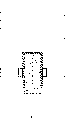
The schematic diagram of Fig. 1, electrode system,
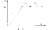
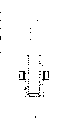
Fig. 2, Fig. 3 diagrammatically illustrate the electrode characteristic of electrode of the electrode system of pulsing operation ionic medium body build-up of luminance process,
Fig. 4, Fig. 5 illustrate the electrode structure of different designs,
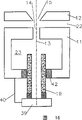
The schematic diagram of Fig. 6, electrode system, similar with Fig. 1,
Fig. 7, roughly the starting voltage of electrode system and the dependence of the pressure in the discharge space be shown, and
Fig. 8 to Figure 18 is the schematic diagram of electrode system with trigger equipment of different structure.
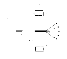
Fig. 1 schematically illustrates the formation that is arranged in the electrode system in the discharge space 10.Discharge space 10 fills with the gas of predetermined pressure and can be made of the electrode of the electrode system of suitable design itself.The pressure of gas can be regulated.The formation of the electrode system of for this reason determining of regulating the needed equipment of gas pressure of discharge space 10 and not illustrating in the drawings.
Two electrodes, first electrode 11, second electrode 12 are arranged.Second electrode 12 constitutes the anode that has central opening 15, and described opening 15 is expanded from electrode intermediate space 22 is outside conically.
Because the described electrode system of the foregoing description can constitute power line when applying tens numerous peoples' for example high pressure, described power line under any circumstance all is parallel to symmetry axis 13 travelings on electrode intermediate space 22 cathetus ground.If voltage is begun to raise with pulse mode from predetermined low value, the voltage rising in other words of the charging slope shown in Fig. 2,3 16 just appears.The ionization process of electrode intermediate space takes place to concentrate on owing to field strength characteristics.Coordinate voltage rising 16 and gas pressure mutually makes because ionization gas discharge occurs on the left branch of Ba Shen curve for this reason, wherein do not constitute plasma tunnel or its plasma, but constitute by the double ionization process in multistage mode by single short time electron avalanche.Therefore plasma distribution has been a cylinder symmetric on bigger degree just at initial period, shown in the plasma schematic diagram among Fig. 1.The plasma 17 that forms is sources of the radiation 17` that will produce.
Obviously only could build-up of luminance plasma 17 when reaching starting voltage Uz.Strive for now in the present invention causing that build-up of luminance occurring postpones 18.Therefore though at build-up of luminance time point tz starting voltage is arranged but correspondingly is delayed.The size that build-up of luminance postpones is regulated by control gaseous pressure.The size that build-up of luminance postpones is that several microseconds arrive several milliseconds scope on the typical time.The prolongation that described build-up of luminance delay causes setting up conductive plasma.Can reach the cylinder symmetric of improving plasma 17 thus.
The pdp body that constitutes after build-up of luminance postpones can be called initial plasma.It can be used for from accumulator to self breakdown feed-in energy in service.As the capacitor group 21 of accumulator, described capacitor group is reaching predetermined starting voltage and is postponing the back discharge shown in Fig. 1, thus can be in plasma the current impulse of the double-digit kiloampere scope of feed-in.So the magnetic field Lorentz force confined plasma that constitutes, thereby high optical density appears, especially constitute far ultraviolet irradiation and Soft X-Ray Beam Irradiated, and described radiation has EUV photoetching necessary wavelength especially.
Replacement postpones 18 by gas pressure to build-up of luminance and exerts one's influence and can also exert one's influence by trigger electrode 19 in addition.Can reach with trigger electrode 19,, also not cause first electrode 11 of discharge, the puncture between second electrode 12 although reach predetermined starting voltage Uz.The trigger delay 20 that can use the trigger electrode 19 shown in Fig. 4,5 to reach shown in Figure 3.This delay is added on build-up of luminance and postpones on 18.Therefore it is particularly advantageous influencing total delay by trigger delay 20, because can utilize measuring technique to reach build-up of luminance time point tz accurately.Still this all is suitable under the situation of use switch element between electrode system and the capacitor group no matter in the operation of the gas discharge of self breakdown.Switch element makes it possible to be higher than the voltage that self breakdown moves needed starting voltage Uz in the electrode system connection.Can be with higher gas pressure work in the in the end described situation, this can reach higher emitted radiation intensity.
It is suitable to measure the build-up of luminance time point, particularly when charging device can be higher than the voltage of predetermined starting voltage Uz on electrode system.Can gather the voltage that is added on the electrode system, that is to say the process of gathering voltage rising 16, for example be added in the time variation of the voltage on first electrode 11, second electrode 12 by collection.Implementing a kind of dU/dt measures.Can also carry out dI/dt and measure, also be exactly to change the time of gathering discharging current.Voltage and current changes suddenly when reaching build-up of luminance time point tz.Can be for example reach predetermined starting voltage Uz and the time between the build-up of luminance time point with digital form with analog form or by means of counter measures at this by means of integrator.This time is transported to controller as measuring amount, and described controller influences gas pressure with this on the meaning of stablizing the build-up of luminance delay.Also be applicable to the situation that adopts trigger delay 20 at this.
Measure and for example can carry out with the starting voltage integrator, described starting voltage integrator bear series connection measure high pressure be added in electrode system or the capacitor group on voltage handle.This starting voltage integrator integration be added on first electrode 11, second electrode 12 by the high pressure of dividing potential drop and keep depositing its whole end by sampling and be worth next charging process.Integral process begins with charging process, just starts with the rising that is added in the voltage on first electrode 11, second electrode 12, and lasts till the duration of determining by timer.The described duration is usually than this height of charging process, thereby can draw the desirable information that postpones size about build-up of luminance.Additionally can use nonlinear element, such as square root extractor, to improve transmission characteristic.Obtain information thus, and, use same measuring-signal although be about the information of starting voltage about postponing.Opposite with the peak detector of measuring starting voltage, described method is insensitive fully to the interference spike that is for example caused by high pressure generator.Do not need to discern the electronic circuit of build-up of luminance time point.
If implement the method without trigger electrode, build-up of luminance time point tz can only be determined by the height of gas pressure.In with the method for trigger electrode, can utilize above-mentioned trigger delay, on demand with select suitable gas pressure to combine to determine the build-up of luminance time point.Determine the charged state of capacitor group 21 at this by the analytical electron circuit, for example by means of above-mentioned starting voltage integrator.Triggering by means of trigger electrode causes, and does not carry out the plasma formation that 21 discharges of capacitor group cause although reached starting voltage Uz.Only under situation about triggering, build-up of luminance just under the situation of sending trigger impulse after the predetermined trigger delay 20 just.Regulated quantity also can be a gas pressure at this, and described gas pressure for example can be regulated by the intake valve of electronics.If after predetermined readout time, do not reach sustaining voltage, just must reduce gas pressure.If behind trigger impulse under the other situation, there is not build-up of luminance just must improve gas pressure.This with the method for trigger electrode in controlled quentity controlled variable be that build-up of luminance postpones after all, just send the time between trigger impulse and the electric voltage dropping.Regulating force value makes build-up of luminance postpone to keep constant in certain tolerance.
In trigger delay 20 illustrated in fig. 3 is about at this illustrational time point that reaches predetermined starting voltage Uz.The time point that also can select each to determine with suitable electronic circuit in principle in advance, for example beginning of charging process or reach predetermined charging voltage value.
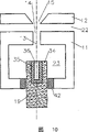
The arrangement of trigger electrode is shown in Fig. 4,5 for example.Trigger electrode 19 is adjacent with negative electrode first electrode 11, but is the side that deviates from anode second electrode 12 at negative electrode.Fit together by insulator 26 at this trigger electrode and negative electrode, wherein the device that first electrode 11, insulator 26 and trigger electrode 19 are assembled together does not illustrate in the drawings.
All form of implementation something in commons of trigger electrode are that they are with respect to symmetry axis 13 symmetric arrangement.All forms of implementation have the axle that aligns with symmetry axis 13.Constitute wall or wall section at this trigger electrode 19.The opening 14 of the trigger electrode and first electrode 11 has predetermined distance.Thereby can reach simultaneously, first electrode 11 is constituted coreless armature, for example constitute hollow cathode.Trigger electrode 19 constitutes the rear wall of negative electrode in fact like this.Such rear wall is a wall 29 under the situation of Fig. 4, and at the bottom of the basin that under the situation of Fig. 5 is basin shape trigger electrode 19 19`.
Basin shape ground constitutes trigger electrode 19 and illustrates, and it not only can be the rear wall of first electrode 11, and can be this coreless armature around the sidewall in space 23.Be further appreciated that trigger electrode 19 is the side wall sections of first electrode 11 fully, it is in electrode potential or cathode potential in addition.
Fig. 4 illustrates, and trigger electrode can be provided with through hole 24, and it plays a part by particle radiation, and described particle radiation at first is to form in the zone of symmetry axis according to the formation of electrode.Can keep the load of trigger electrode within the acceptable range with such through hole.Particle radiation is accepted by the part that is in cathode potential of electrode system.Under the situation of Fig. 5, also can adopt through hole 24.
Through hole 24 shown in Figure 4 is parallel to thorax hole 24`.Described thorax hole 24` can play gas thorax hole, just is used to pass through gas on the meaning of air inlet.Also can utilize through hole 24 on the meaning of such air pressure stream or on the meaning in air inlet.The two all is particularly advantageous if electrode system itself constitutes discharge space.
In protruding into space 23, use under the situation of gas discharge and will consider the evaporation of metallic vapour insulator 26.Such evaporation can cause insulator 26 short circuits, and for it is shielded the metallic vapour that arrives, first electrode 11 is provided with annular ring 27.Described annular ring 27 and opening 14 are concentric and overlap with the insulator of toroid.Trigger electrode 19 is provided with the depression 28 of annular in addition.Annular ring 27 is packed in the ring-shaped depression 28.Keep the current potential distance separating thus, because usually very little current potential only needs less current potential separation distance between negative electrode 11 and trigger electrode 19.
Fig. 4,5 trigger electrode also can be connected with hollow anode.Light at plasma 17 in such cases must be from first electrode 11 or from hollow negative electrode output.Yet more advantageously light is from anode side output, as shown in Figure 1, and with the high drive negative electrode of bearing, avoids spraying the chip that sends with electrion at electrode system because like this can be preferably in observer's part.
Thereby before sending trigger impulse, before triggering low ohm plasma discharge, select the current potential of trigger electrode 19, extract charge carrier out in the feasible electrode intermediate space from coreless armature or hollow cathode and thorax bore region.This for example applies the positive potential that is generally 100V by target current potential on trigger electrode 19 and carries out.Send trigger impulse then, wherein the current potential of trigger electrode drops to cathode potential, perhaps wherein adds negative current potential on trigger electrode 19.The typical time constant of current potential that changes trigger electrode 19 at this advantageously in the scopes of number nanoseconds to hundreds of nanoseconds.
In order to reach high light utilization efficiency, pursue and keep the repetition rate of discharge highly as much as possible, just in the scope of a plurality of kHz, and preferably more than 10kHz.This desired repetition rate in other words the reorganization time of plasma reach capacity.This limit depends on the gas type of the described method of using of operation.Consider to use xenon especially in order in the EUV scope, to obtain the high radiant rate people.When adopting pure xenon work, self breakdown seldom reaches the repetition rate more than about 1kHz in the pulse energy scope of erg-ten to 10 joule.Therefore pursue the measure of quickening repetition rate of carrying out.
A kind of possibility is to adopt mist.Can reach behind capacitor set discharge, recombinate quickly plasma, for example mixing air, forming gas, nitrogen, oxygen or halogen by mist.
Can transfer out charged particle from the zone of opening 14,15 by suitable air-flow support in addition.At this advantageously with by negative electrode and/or the charge air flow by the electrode intermediate space with passing through anode, promptly among Fig. 1 towards observer's electrode, the air-flow of bleeding.Can produce pressure decline at anode region or coreless armature zone with such air-flow.Can prolong plasma 17 with such barometric gradient, transmit to reach the higher EUV radiation in arriving at user's observation path thus.
The measure of other raising repetition rate can be carried out in conjunction with capacitor group 21.Can be at this from low ohm plasma being lasted till that hundreds of microseconds set about according to condition.Can correspondingly charge to the capacitor group quickly than the settling time of low ohm plasma now.Therefore can abandon the plasma of recombinating fully.In addition even can light high ohm plasma between two discharges between opening 14,15, this can cause the good conditions of the initial plasma of high current discharge.
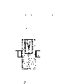
Fig. 6 schematically illustrates the electrode system that is arranged in the discharge space 10.Discharge space 10 fills the gas with predetermined gas pressure, and can be made of the electrode of the electrode system that suitably constitutes itself.The pressure of gas can be regulated.The electrode system that but the needed equipment of adjustments of gas pressure of existing discharge space 10 is not shown in the drawings and determines for this reason.
Because above-mentioned configuration, described electrode system can constitute power line when the high pressure that for example connects tens of kilovolts, and described power line under any circumstance all is parallel to symmetry axis 13 on electrode intermediate space 22 cathetus ground.If voltage is begun to rise with pulse mode from the low value of being scheduled to, the voltage rising in other words of charging slope just appears.The ionization process of electrode intermediate space takes place to concentrate on owing to field strength characteristics.Coordinate mutually for this reason that voltage rises and gas pressure makes owing to ionization appears at gas discharge on the left branch of Ba Shen curve, do not constitute plasma tunnel or its plasma at this, but constitute by the double ionization process multistagely by single short time electron avalanche.Therefore plasma distribution has been a cylinder symmetric on bigger degree just at initial period, shown in the plasma schematic diagram among Fig. 6.The plasma 17 that forms is sources of the radiation 17` that will produce, i.e. the source of a kind of electronic emission.
The plasma that constitutes can be called initial plasma.It can be used energy from accumulator to self breakdown feed-in in service.As the capacitor group 21 of accumulator, described capacitor group is reaching predetermined starting voltage and is postponing the back discharge shown in Fig. 6, thus can be in plasma the current impulse of feed-in two digits kiloampere scope.So the magnetic field Lorentz force confined plasma that constitutes, thereby high optical density appears, especially constitute far ultraviolet irradiation and Soft X-Ray Beam Irradiated, and described radiation has EUV photoetching necessary wavelength especially.
Electrode system shown in Fig. 6 is provided with trigger equipment in the electrode zone of first electrode 11.First electrode 11 has trigger electrode 19 along electrode symmetry axis 13 for this reason, and described trigger electrode 19 is remained on by insulator 26 at the end 30 of first electrode 11.Working of insulator 26 be, can apply the current potential different with first electrode 11 for trigger electrode 19.Have the parasitic capacitance 31 that switch 32 measures that is parallel at this trigger electrode 19, can take described trigger electrode 19, first electrode 11 to identical current potential with described switch 32 about first electrode 11.
Usually, second electrode 12 constitutes anode and ground connection as shown in figure.The phase anticathode is in negative potential-V and trigger electrode 19 is in current potential-V+Vt.The current potential of trigger electrode is higher than first electrode 11 before the beginning of trigger process.For the purpose that triggers, send trigger impulse by connecting switch 32, so the current potential of trigger electrode is reduced to the current potential of first electrode 11.The scope of typical time constant in several nanoseconds to hundreds of nanosecond that changes at the current potential of this trigger electrode 19 is favourable.
The electrode arrangement that schematically illustrates in Fig. 6 is generally, and between first electrode 11, second electrode 12 1 to 10 mm distance is arranged.The minimum tunnel of opening 14,15 is typically at 1 to 10 millimeter.The capacity in the space 23 in constituting first electrode 11 of hollow cathode is typically at 1 to 10 cubic centimetre.Gas pressure is between 0.01 to 1 millibar.Electrode voltage is generally 3 to 30kV, and the potential difference between the trigger electrode 19 and first electrode 11 is between 50 volts to 1000 volts.
The voltage that punctures just takes place and complys with mutually corresponding to the pressure of curve shown in Fig. 7 in starting voltage in principle between first electrode 11, second electrode 12.Left branch to this Ba Shen curve shown in Figure 7.
The left curve of Fig. 7 is applicable to the operation of the device of non-triggering.Have only single breakdown point on the curve of this V=0, described breakdown point is about 8kV under the gas pressure of 7Pa for example.Other pressure in the space 23 causes the starting voltage that other is correspondingly arranged.Yet trigger voltage, just the potential difference between the trigger electrode 19 and first electrode 11 also can deviate from 0.Vt is not equal to 0 but for example equal V1 or V2 in the case.Therefore can reach with different parameters by suitable measurement and move described device trigger voltage Vt.Obtain the possibility that pressure shown in Figure 7 changes for the predetermined voltage on first electrode 11, second electrode 12.Also be that predetermined pressure is had change in voltage shown in Figure 2 in a similar fashion.Yet correspondingly also can determine the time point of puncture exactly, and not appear at the working range that above-mentioned difficulty wherein takes place thus with triggering signal.Especially can by the needs used of requirement select repetition rate, for example in 10 to 20kHz scope.Can also be work interval at the repetition rate of predetermined fixed, thus can be in the desirable radiation energy needed of saving generation between interval of working.Can improve the stability of working point significantly.
Triggering reaches by the circuit shown in Fig. 6.To 21 chargings of capacitor group, wherein first electrode 11 connects negative voltage and second electrode, 12 ground connection.The connection of first electrode 11, second electrode 12 all is connected with capacitor group 21 by low inductive circuit.High ohm circuit is connected trigger electrode 19 with first electrode 11, connection described herein can disconnect by switch 32.Under situation about disconnecting, 19 pairs first electrodes 11 of trigger electrode have potential difference Vt.For this situation, regulate the gas pressure in the space 23 of voltage on first electrode 11, second electrode 12 and the electrode intermediate space or first electrode 11, make the build-up of luminance that when inserting trigger voltage Vt, can not carry out plasma 17.If opposite Closing Switch 32 has just been eliminated the current potential that potential difference Vt and trigger electrode 19 obtain first electrode 11, wherein, the voltage source of protective resistance 33 protection trigger voltages.
When cut-off switch 32, but might at the trigger electrode 19 of Fig. 6 and rise between the electrode 12 of anodize to constitute and conduct electricity the tunnel with corresponding particle radiation, this conduction tunnel can discharge the energy of capacitor group 21 and may cause damaging circuits for triggering.So the trigger electrode that in the system of the main electrode 11,12 that schematically illustrates Fig. 8 to 18 illustrate, constitutes by different way, these trigger electrodes can work to the perfect functions of device.
Fig. 8 to 18 illustrate with by first electrode 11, second electrode 12 with and the trigger electrode 19 arranged with coaxial manner of the symmetry axis 13 that constitutes of opening 14,15.The trigger electrode 19 of this Fig. 8 to 13 be configured they a front 34 towards opening 14.Yet should be respectively equipped with the corresponding different shielding 35 that constitutes in front 34 at least.Each shielding 35 is big at least to corresponding with the diameter of opening 14,15.Just shield near 35 zones that particle radiation constitutes trigger electrode 19.
Under the situation of Fig. 8, shielding 35 is constituted the insulator of form of layer in the front 34 of the trigger electrode 19 that is laid in.Under the situation of Fig. 9, will shield 35 equally and constitute insulator, yet but be the body that constitutes in the front 34 of the trigger electrode 39 of packing into.The cross section of described body for example is cylindrical, is used for putting in the mode of routine the thorax holes from positive 34 introducings of trigger electrode 19.In Figure 10 and Figure 11, constitute in the same manner among trigger electrode and Fig. 9.Yet the different shielding 35 of in its thorax hole, but packing into.The shielding 35 of Figure 10 still is columniform body, but a coaxial depression 36 that constitutes blind hole is but arranged.The diameter adjustment of this blind hole is arrived the diameter of potential particle radiation.Shielding 35 formations of Figure 11 deviate from the depression 36 that opening 14,15 far goes conical tapered.The particle radiation that constitutes hits on the relatively large face of shielding, thus the Energy distribution of radiation on bigger surface, this has been avoided local pyrexia.Described depression all is applicable to and absorbs because the fragmentary product that particle radiation produces under Figure 10,11 two kinds of situations, and these fragmentary products can be deposited on remaining face of this arrangement of little interference on the inwall of depression 36.
Figure 12,13 trigger electrode be characterised in that, they are fully kept apart the space 23 that has a common boundary with first electrode 11 at least with shielding.Described shielding 35 is a kind of coating, exposes its surface on the described less position that covers trigger electrode 19.Therefore the little electric field inhomogeneities of exposing decision by this may appear.But may on the surface of shielding 35, assembling electric charge under certain discharging condition, work to cover trigger voltage.Cover the functional fault that trigger voltage can cause device.Have the residue conductivity that reduces the surface charge of setting up even as big as neutralization in other words if shield 35, just can avoid described bridging effect.Such residue conductivity can not be greatly to allowing second electrode 12 and trigger electrode 19 flow through the electric current that capacitor group 12 is significantly discharged.Figure 13 illustrates such shielding 35 with suitable residue conductivity.
Can in wide limit, change in all above-mentioned form of implementation mesoscales.Thereby trigger electrode 19 for example also may be embodied as thin line, and this suitably illustrates according to Figure 12,13.
The trigger electrode 19 of Figure 14 to 16 is hollow cylinders.This trigger electrode is also arranged coaxially with symmetry axis 13.Because its hollow enforcement and remaining constitute, the particle radiation that constitutes in symmetry axis 13 zones does not arrive at trigger electrode 19 and takes place to disturb or destroy.Trigger electrode 19 is by the ends 37 sealing of metal among Figure 14, and described metal bottom is in earth potential and to trigger electrode 19 insulation of hollow cylinder.Can not the constituent particle radiation between the end 37 and second electrode 12, because this electrode similarly is in earth potential as anode.
In Figure 16, the end 38, be constituted as insulator, thereby particle radiation is played same purpose as shielding as described in Fig. 8 to 11.Among Figure 16, the end 39 of hollow cylinder trigger electrode 19, be implemented as the electrode of metal, it and first electrode 11, and promptly negative electrode connects conductively.Be transported to second electrode 12 along the charge carrier of the particle radiation of symmetry axis by means of the wiring 40 of this metal.
Figure 17 and 18 arrangement are the accommodations of the arrangement of Figure 16.The charge particle that is under all these situations in symmetry axis 13 and the space 23 all is transported to first electrode 11.Trigger electrode 19 constitutes ring segment in Figure 17.Described ring segment laterally is embedded in first electrode 11 symmetry axis 13 of first electrode 11, second electrode 12.Its first half is connected by the lead 41 that is shown in broken lines with the latter half in Figure 17, therefore has identical current potential.The arrangement of trigger electrode 19 is symmetrical with respect to symmetry axis 13.In the situation of Figure 18, be so no longer but.During this arranges, until lead 41, the arrangement on the side shown in Figure 17.But symmetry axis 13 is but perpendicular to illustrated plane in Figure 18, and the part 19` and the 19`` of two identical formations of coaxial and trigger electrodes that laterally arrange with respect to symmetry axis 13 shown in Figure 18.Part 19`, 19`` represent electrode stem.Replace two part 19` and the described electrode of 19`` also can have a plurality of parts.
The shielding used at trigger electrode 19 places 35 is made up of heat-resistant insulation material, for example Al2O3, quartz or carborundum.The described material that uses for shielding 35 all is connected with trigger electrode 19 good heat conductive ground.
Claims (19)
1. utilize gas discharge on the left branch be operated in the Ba Shen curve to produce the method for far ultraviolet irradiation and Soft X-Ray Beam Irradiated,
Wherein in discharge space (10), adopt predetermined gas pressure and first (11) electrode and second electrode (12), described two electrodes (11,12) respectively have an opening (14,15) that is positioned at same symmetry axis (13), and form the plasma (17) that is in its opening (14,15) zone when in voltage rises the process of (16), reaching predetermined starting voltage (Uz), described plasma is the source of the radiation (17`) that will produce
Wherein by gas pressure being exerted one's influence and/or by triggering build-up of luminance plasma (17),
And wherein when plasma (17) build-up of luminance accumulator by means of first electrode (11) and the second electrode electrode (12) feed-in energy stored in plasma (17),
It is characterized in that,
Adopt its current potential before trigger process begins, to be higher than the build-up of luminance that carries out plasma (17) as the trigger electrode (19) of first electrode (11) of negative electrode and first electrode (11) in second electrode (12).
2. the method for claim 1,
It is characterized in that,
With respect to the voltage of regulating trigger electrode (19) as first electrode (11) of negative electrode and the voltage on first electrode (11) and second electrode (12) and the gas pressure of discharge space (10), make the build-up of luminance that when applying trigger voltage, does not carry out plasma (17), and by turn-offing the build-up of luminance that trigger voltage just causes plasma.
3. method as claimed in claim 1 or 2,
It is characterized in that,
Implement described method with the repetition rate between>0Hz and the 100kHz.
4. as claim 1 or 2 described methods,
It is characterized in that,
Turn-off the operation interval operation of length with connect length and scalable by scalable, and correspondingly adopt fixing repetition rate.
5. utilize gas discharge on the left branch be operated in the Ba Shen curve to produce the device of far ultraviolet irradiation and Soft X-Ray Beam Irradiated,
Predetermined gas pressure and first electrode (11) and second electrode (12) are wherein arranged in discharge space (10), described two electrodes respectively have an opening (14,15) that is positioned on the same symmetry axis (13), and has the plasma (17) that is in its opening (14,15) zone when in voltage rises the process of (16), reaching predetermined starting voltage (Uz), described plasma is the source of the radiation (17`) that will produce
Wherein in the space (23) adjacent, there is trigger electrode (19) to be used for being undertaken the build-up of luminance of plasma (17) by triggering with first electrode (11),
And wherein have by means of described first electrode (11) and second electrode (11) accumulator in the plasma (17) advanced in the energy stored feed-in,
It is characterized in that,
Trigger electrode (19) is arranged in along outside the particle radiation of symmetry axis (13) generation, perhaps has the shielding (35) that stops the latter.
6. device as claimed in claim 5,
It is characterized in that,
Trigger electrode (11) is arranged and had insulator at least as shielding (35) in the zone that forms particle radiation towards the front (34) of opening (14,15) along the symmetry axis (13) of described first electrode (11) and second electrode (12) opening (14,15).
7. device as claimed in claim 6,
It is characterized in that,
Described insulator is constituted the layer on the front (34) of the trigger electrode that is laid in (19).
8. device as claimed in claim 6,
It is characterized in that,
Described insulator constituted the body in the front (34) that to put into trigger electrode (19).
9. device as claimed in claim 8,
It is characterized in that,
Described insulator has a depression (36), and depression (36) has the cross section that is aligned on the particle radiation.
10. device as claimed in claim 9,
It is characterized in that,
Circular cone constitutes the depression (36) of described insulator with converging.
11. as the described device of one of claim 5 to 10,
It is characterized in that,
Trigger electrode (19) is insulated fully to the space (23) that has a common boundary with first electrode (19) at least.
12. as the described device of one of claim 5 to 10,
It is characterized in that,
The shielding (35) of trigger electrode (19) has to be eliminated surface charge and stops second electrode (12) and trigger electrode (19) to influence the residue conductivity of the electric current of discharge.
13. device as claimed in claim 5,
It is characterized in that,
Trigger electrode (19) is constituted hollow cylinder around symmetry axis.
14. device as claimed in claim 13,
It is characterized in that,
The trigger electrode of described hollow cylinder (19) has an end that deviates from first electrode (11) and second electrode (12), the described end, constitute with insulator, or have the metal bottom of one of first electrode (11) and second electrode (12) current potential, and the described end and trigger electrode (19) insulation.
15. device as claimed in claim 5,
It is characterized in that,
Trigger electrode (19) is ring segment or is laterally to embed electrode stem in first electrode (11) with respect to first electrode (11) and second electrode (12) symmetry axis (13) at least.
16. as the described device of one of claim 5 to 10,
It is characterized in that,
Trigger electrode (19) insulation is embedded in first electrode (11).
17. as the described device of one of claim 5 to 10,
It is characterized in that,
Shielding (35) is with heat-resisting insulating material manufacturing.
18. as the described device of one of claim 5 to 10,
It is characterized in that,
Shielding (35) is connected with trigger electrode (19) good heat conductive ground.
19. as the described device of one of claim 5 to 10,
It is characterized in that,
Shielding (35) has at least the suitable diameter of diameter with opening (14,15).
Applications Claiming Priority (7)
| Application Number | Priority Date | Filing Date | Title |
|---|---|---|---|
| DE10117377 | 2001-04-06 | ||
| DE10117377.6 | 2001-04-06 | ||
| DE10139677A DE10139677A1 (en) | 2001-04-06 | 2001-08-11 | Method and device for generating extremely ultraviolet radiation and soft X-rays |
| DE10139677.5 | 2001-08-11 | ||
| EP01125762A EP1248499B1 (en) | 2001-04-06 | 2001-10-29 | Method and apparatus for production of extreme ultraviolet radiation |
| EP01125762.3 | 2001-10-29 | ||
| PCT/DE2002/001085 WO2002082872A1 (en) | 2001-04-06 | 2002-03-23 | Method and device for producing extreme ultraviolet radiation and soft x-radiation |
Publications (2)
| Publication Number | Publication Date |
|---|---|
| CN1531840A CN1531840A (en) | 2004-09-22 |
| CN1311716C true CN1311716C (en) | 2007-04-18 |
Family
ID=26009027
Family Applications (1)
| Application Number | Title | Priority Date | Filing Date |
|---|---|---|---|
| CNB02807825XA Expired - Fee Related CN1311716C (en) | 2001-04-06 | 2002-03-23 | Method and device for producing extreme ultraviolet radiation and soft X-radiation |
Country Status (8)
| Country | Link |
|---|---|
| US (1) | US7126143B2 (en) |
| EP (2) | EP1248499B1 (en) |
| JP (1) | JP4330344B2 (en) |
| CN (1) | CN1311716C (en) |
| AT (1) | ATE469533T1 (en) |
| DE (3) | DE10139677A1 (en) |
| TW (1) | TWI284916B (en) |
| WO (1) | WO2002082872A1 (en) |
Families Citing this family (25)
| Publication number | Priority date | Publication date | Assignee | Title |
|---|---|---|---|---|
| DE10238096B3 (en) * | 2002-08-21 | 2004-02-19 | Fraunhofer-Gesellschaft zur Förderung der angewandten Forschung e.V. | Gas discharge lamp for extreme UV lithography or X-ray microscopy has tapered electrode opening for transport of charge carriers from external region to discharge space |
| US6770895B2 (en) | 2002-11-21 | 2004-08-03 | Asml Holding N.V. | Method and apparatus for isolating light source gas from main chamber gas in a lithography tool |
| DE10256663B3 (en) * | 2002-12-04 | 2005-10-13 | Fraunhofer-Gesellschaft zur Förderung der angewandten Forschung e.V. | Gas discharge lamp for EUV radiation |
| DE10260458B3 (en) | 2002-12-19 | 2004-07-22 | Xtreme Technologies Gmbh | Radiation source for production of extreme ultraviolet radiation, useful in research into smaller transistors from the micrometer to the nanometer range, is based on dense hot plasma obtained by gas discharge |
| JP2004226244A (en) * | 2003-01-23 | 2004-08-12 | Ushio Inc | Extreme ultra-violet light source and semiconductor aligner |
| DE10310623B8 (en) * | 2003-03-10 | 2005-12-01 | Fraunhofer-Gesellschaft zur Förderung der angewandten Forschung e.V. | Method and apparatus for generating a plasma by electrical discharge in a discharge space |
| US6919573B2 (en) | 2003-03-20 | 2005-07-19 | Asml Holding N.V | Method and apparatus for recycling gases used in a lithography tool |
| DE10336273A1 (en) * | 2003-08-07 | 2005-03-10 | Fraunhofer Ges Forschung | Device for generating EUV and soft X-radiation |
| DE10359464A1 (en) | 2003-12-17 | 2005-07-28 | Fraunhofer-Gesellschaft zur Förderung der angewandten Forschung e.V. | Method and device for generating in particular EUV radiation and / or soft X-radiation |
| WO2006056917A1 (en) | 2004-11-29 | 2006-06-01 | Philips Intellectual Property & Standards Gmbh | Method and apparatus for generating radiation in the wavelength range from about 1 nm to about 30 nm, and use in a lithography device or in metrology |
| DE102004058500A1 (en) * | 2004-12-04 | 2006-06-08 | Philips Intellectual Property & Standards Gmbh | Method and device for operating an electrical discharge device |
| DE102005025624B4 (en) * | 2005-06-01 | 2010-03-18 | Xtreme Technologies Gmbh | Arrangement for generating intense short-wave radiation based on a gas discharge plasma |
| JP2008544448A (en) * | 2005-06-14 | 2008-12-04 | コーニンクレッカ フィリップス エレクトロニクス エヌ ヴィ | Method for protecting radiation sources generating EUV radiation and / or soft X-rays from short circuits |
| DE102006022823B4 (en) * | 2006-05-12 | 2010-03-25 | Xtreme Technologies Gmbh | Arrangement for generating EUV radiation based on a gas discharge plasma |
| US7687788B2 (en) * | 2007-07-16 | 2010-03-30 | Asml Netherlands B.V. | Debris prevention system, radiation system, and lithographic apparatus |
| US8493548B2 (en) * | 2007-08-06 | 2013-07-23 | Asml Netherlands B.V. | Lithographic apparatus and device manufacturing method |
| US7655925B2 (en) | 2007-08-31 | 2010-02-02 | Cymer, Inc. | Gas management system for a laser-produced-plasma EUV light source |
| US20090134129A1 (en) * | 2007-11-27 | 2009-05-28 | General Electric Company | Ablative plasma gun apparatus and system |
| DE102007060807B4 (en) * | 2007-12-18 | 2009-11-26 | Fraunhofer-Gesellschaft zur Förderung der angewandten Forschung e.V. | Gas discharge source, in particular for EUV radiation |
| NL1036595A1 (en) * | 2008-02-28 | 2009-08-31 | Asml Netherlands Bv | Device constructed and arranged to generate radiation, lithographic apparatus, and device manufacturing method. |
| EP2308272B1 (en) * | 2008-07-28 | 2012-09-19 | Philips Intellectual Property & Standards GmbH | Method and device for generating euv radiation or soft x-rays |
| US20110109226A1 (en) * | 2009-11-06 | 2011-05-12 | Agilent Technologies, Inc. | Microplasma device with cavity for vacuum ultraviolet irradiation of gases and methods of making and using the same |
| CN102625557A (en) * | 2012-03-30 | 2012-08-01 | 大连理工大学 | Generating device for atmospheric bare electrode cold plasma jet |
| KR101542333B1 (en) * | 2014-12-26 | 2015-08-05 | 한국과학기술연구원 | Apparatus for extreme ultra-violet beam generation using multi-gas cell module |
| CN114442437A (en) * | 2020-10-30 | 2022-05-06 | 上海宏澎能源科技有限公司 | Light source device |
Citations (4)
| Publication number | Priority date | Publication date | Assignee | Title |
|---|---|---|---|---|
| US4201921A (en) * | 1978-07-24 | 1980-05-06 | International Business Machines Corporation | Electron beam-capillary plasma flash x-ray device |
| US4596030A (en) * | 1983-09-10 | 1986-06-17 | Carl Zeiss Stiftung | Apparatus for generating a source of plasma with high radiation intensity in the X-ray region |
| US5050178A (en) * | 1988-04-26 | 1991-09-17 | Siemens Aktiengesellschaft | Multichannel pseudo-spark switch and excitation circuit for gas lasers having the switch |
| WO2001001736A1 (en) * | 1999-06-29 | 2001-01-04 | Fraunhofer-Gesellschaft zur Förderung der angewandten Forschung e.V. | Device for producing an extreme ultraviolet and soft x radiation from a gaseous discharge |
Family Cites Families (6)
| Publication number | Priority date | Publication date | Assignee | Title |
|---|---|---|---|---|
| FR2551614B1 (en) * | 1983-09-02 | 1986-03-21 | Centre Nat Rech Scient | INTENSE SOFT X-RAY SOURCE, WITH CYLINDRICAL COMPRESSION OF PLASMA, THIS PLASMA BEING OBTAINED FROM AN EXPLOSED SHEET |
| DE19753696A1 (en) * | 1997-12-03 | 1999-06-17 | Fraunhofer Ges Forschung | Device and method for generating extreme ultraviolet radiation and soft X-rays from a gas discharge |
| TWI246872B (en) * | 1999-12-17 | 2006-01-01 | Asml Netherlands Bv | Radiation source for use in lithographic projection apparatus |
| TW518913B (en) * | 2000-07-03 | 2003-01-21 | Asml Netherlands Bv | Radiation source, lithographic apparatus, and semiconductor device manufacturing method |
| TW503669B (en) * | 2000-07-04 | 2002-09-21 | Lambda Physik Ag | Method of producing short-wave radiation from a gas-discharge plasma and device for implementing it |
| RU2206186C2 (en) * | 2000-07-04 | 2003-06-10 | Государственный научный центр Российской Федерации Троицкий институт инновационных и термоядерных исследований | Method and device for producing short-wave radiation from gas-discharge plasma |
-
2001
- 2001-08-11 DE DE10139677A patent/DE10139677A1/en not_active Withdrawn
- 2001-10-29 AT AT01125762T patent/ATE469533T1/en not_active IP Right Cessation
- 2001-10-29 DE DE50115489T patent/DE50115489D1/en not_active Expired - Lifetime
- 2001-10-29 EP EP01125762A patent/EP1248499B1/en not_active Expired - Lifetime
-
2002
- 2002-03-12 TW TW091104540A patent/TWI284916B/en active
- 2002-03-23 US US10/474,121 patent/US7126143B2/en not_active Expired - Fee Related
- 2002-03-23 DE DE10291549T patent/DE10291549D2/en not_active Expired - Fee Related
- 2002-03-23 JP JP2002580685A patent/JP4330344B2/en not_active Expired - Fee Related
- 2002-03-23 EP EP02729817A patent/EP1374650A1/en not_active Withdrawn
- 2002-03-23 WO PCT/DE2002/001085 patent/WO2002082872A1/en active Application Filing
- 2002-03-23 CN CNB02807825XA patent/CN1311716C/en not_active Expired - Fee Related
Patent Citations (4)
| Publication number | Priority date | Publication date | Assignee | Title |
|---|---|---|---|---|
| US4201921A (en) * | 1978-07-24 | 1980-05-06 | International Business Machines Corporation | Electron beam-capillary plasma flash x-ray device |
| US4596030A (en) * | 1983-09-10 | 1986-06-17 | Carl Zeiss Stiftung | Apparatus for generating a source of plasma with high radiation intensity in the X-ray region |
| US5050178A (en) * | 1988-04-26 | 1991-09-17 | Siemens Aktiengesellschaft | Multichannel pseudo-spark switch and excitation circuit for gas lasers having the switch |
| WO2001001736A1 (en) * | 1999-06-29 | 2001-01-04 | Fraunhofer-Gesellschaft zur Förderung der angewandten Forschung e.V. | Device for producing an extreme ultraviolet and soft x radiation from a gaseous discharge |
Also Published As
| Publication number | Publication date |
|---|---|
| CN1531840A (en) | 2004-09-22 |
| EP1248499A1 (en) | 2002-10-09 |
| EP1248499B1 (en) | 2010-05-26 |
| ATE469533T1 (en) | 2010-06-15 |
| EP1374650A1 (en) | 2004-01-02 |
| WO2002082872A1 (en) | 2002-10-17 |
| JP4330344B2 (en) | 2009-09-16 |
| JP2004530269A (en) | 2004-09-30 |
| DE10291549D2 (en) | 2004-04-15 |
| US7126143B2 (en) | 2006-10-24 |
| DE10139677A1 (en) | 2002-10-17 |
| TWI284916B (en) | 2007-08-01 |
| US20040183037A1 (en) | 2004-09-23 |
| DE50115489D1 (en) | 2010-07-08 |
Similar Documents
| Publication | Publication Date | Title |
|---|---|---|
| CN1311716C (en) | Method and device for producing extreme ultraviolet radiation and soft X-radiation | |
| US8735766B2 (en) | Cathode assembly and method for pulsed plasma generation | |
| KR20140086928A (en) | Generating a highly ionized plasma in a plasa chamber | |
| SE469810B (en) | Device for ion plasma electron gun and methods for generating secondary electrons from an ion plasma electron gun | |
| JP6419078B2 (en) | Ion implantation apparatus having a plurality of plasma source parts | |
| WO2007127070A3 (en) | Multistrike gas discharge lamp ignition apparatus and method | |
| EP2482303A2 (en) | Deposition apparatus and methods | |
| WO2009018838A1 (en) | Cathode assembly and method for pulsed plasma generation | |
| US4034260A (en) | Gridded crossed-field tube and ignition method | |
| KR100674031B1 (en) | Plasma gun for thin film deposition and thin film deposition apparatus thereof | |
| RU134728U1 (en) | FORWARE SOURCE OF PULSE ELECTRON BEAM | |
| RU2305344C2 (en) | Method for pre-burning contact gap in vacuum switches by means of high voltage | |
| JP2019504475A (en) | Control method of plasma immersion ion implantation apparatus and bias supply apparatus | |
| KR0141604B1 (en) | Method for spot knocking an electron gun mount assembly of a crt | |
| US20150243413A1 (en) | Solid-State Resistor for Pulsed Power Machines | |
| Lan et al. | Mode transition of vacuum arc discharge and its effect on ion current | |
| RU2759425C1 (en) | Plasma emitter of a pulse forevacuum electron source based on an arc discharge | |
| RU2676756C1 (en) | Gas discharge switchboard | |
| EP1145269B1 (en) | Method for generating a pulsed electron beam and a trigger plasma source for carrying out said method | |
| RU2529879C1 (en) | Cathode plasma flux stabiliser | |
| RU203107U1 (en) | High-current electron gun | |
| Nazarov et al. | A source of high-density pulsed electron beams with energies up to 40 keV | |
| RU48105U1 (en) | VACUUM-ARC SOURCE OF METAL IONS | |
| KR100813694B1 (en) | Plasma focus apparatus | |
| Nikolaev et al. | Production of Multiply Charged Bismuth Ion Beams in a Vacuum Arc Ion Source with a Submicrosecond Pulse Duration |
Legal Events
| Date | Code | Title | Description |
|---|---|---|---|
| C06 | Publication | ||
| PB01 | Publication | ||
| C10 | Entry into substantive examination | ||
| SE01 | Entry into force of request for substantive examination | ||
| C14 | Grant of patent or utility model | ||
| GR01 | Patent grant | ||
| C17 | Cessation of patent right | ||
| CF01 | Termination of patent right due to non-payment of annual fee |
Granted publication date: 20070418 Termination date: 20120323 |