CN1306294C - Microstructure optical fiber and its mfg. method - Google Patents
Microstructure optical fiber and its mfg. method Download PDFInfo
- Publication number
- CN1306294C CN1306294C CNB031082335A CN03108233A CN1306294C CN 1306294 C CN1306294 C CN 1306294C CN B031082335 A CNB031082335 A CN B031082335A CN 03108233 A CN03108233 A CN 03108233A CN 1306294 C CN1306294 C CN 1306294C
- Authority
- CN
- China
- Prior art keywords
- optical fiber
- hole
- grid
- lattice point
- interior zone
- Prior art date
- Legal status (The legal status is an assumption and is not a legal conclusion. Google has not performed a legal analysis and makes no representation as to the accuracy of the status listed.)
- Expired - Fee Related
Links
Images


Classifications
-
- G—PHYSICS
- G02—OPTICS
- G02B—OPTICAL ELEMENTS, SYSTEMS OR APPARATUS
- G02B6/00—Light guides; Structural details of arrangements comprising light guides and other optical elements, e.g. couplings
- G02B6/02—Optical fibres with cladding with or without a coating
- G02B6/02214—Optical fibres with cladding with or without a coating tailored to obtain the desired dispersion, e.g. dispersion shifted, dispersion flattened
- G02B6/02219—Characterised by the wavelength dispersion properties in the silica low loss window around 1550 nm, i.e. S, C, L and U bands from 1460-1675 nm
- G02B6/02228—Dispersion flattened fibres, i.e. having a low dispersion variation over an extended wavelength range
- G02B6/02238—Low dispersion slope fibres
-
- G—PHYSICS
- G02—OPTICS
- G02B—OPTICAL ELEMENTS, SYSTEMS OR APPARATUS
- G02B6/00—Light guides; Structural details of arrangements comprising light guides and other optical elements, e.g. couplings
-
- C—CHEMISTRY; METALLURGY
- C03—GLASS; MINERAL OR SLAG WOOL
- C03B—MANUFACTURE, SHAPING, OR SUPPLEMENTARY PROCESSES
- C03B37/00—Manufacture or treatment of flakes, fibres, or filaments from softened glass, minerals, or slags
- C03B37/01—Manufacture of glass fibres or filaments
- C03B37/012—Manufacture of preforms for drawing fibres or filaments
- C03B37/01205—Manufacture of preforms for drawing fibres or filaments starting from tubes, rods, fibres or filaments
- C03B37/01211—Manufacture of preforms for drawing fibres or filaments starting from tubes, rods, fibres or filaments by inserting one or more rods or tubes into a tube
- C03B37/0122—Manufacture of preforms for drawing fibres or filaments starting from tubes, rods, fibres or filaments by inserting one or more rods or tubes into a tube for making preforms of photonic crystal, microstructured or holey optical fibres
-
- C—CHEMISTRY; METALLURGY
- C03—GLASS; MINERAL OR SLAG WOOL
- C03B—MANUFACTURE, SHAPING, OR SUPPLEMENTARY PROCESSES
- C03B37/00—Manufacture or treatment of flakes, fibres, or filaments from softened glass, minerals, or slags
- C03B37/01—Manufacture of glass fibres or filaments
- C03B37/012—Manufacture of preforms for drawing fibres or filaments
- C03B37/01205—Manufacture of preforms for drawing fibres or filaments starting from tubes, rods, fibres or filaments
- C03B37/01225—Means for changing or stabilising the shape, e.g. diameter, of tubes or rods in general, e.g. collapsing
- C03B37/01228—Removal of preform material
- C03B37/01231—Removal of preform material to form a longitudinal hole, e.g. by drilling
-
- C—CHEMISTRY; METALLURGY
- C03—GLASS; MINERAL OR SLAG WOOL
- C03C—CHEMICAL COMPOSITION OF GLASSES, GLAZES OR VITREOUS ENAMELS; SURFACE TREATMENT OF GLASS; SURFACE TREATMENT OF FIBRES OR FILAMENTS MADE FROM GLASS, MINERALS OR SLAGS; JOINING GLASS TO GLASS OR OTHER MATERIALS
- C03C13/00—Fibre or filament compositions
- C03C13/04—Fibre optics, e.g. core and clad fibre compositions
-
- G—PHYSICS
- G02—OPTICS
- G02B—OPTICAL ELEMENTS, SYSTEMS OR APPARATUS
- G02B6/00—Light guides; Structural details of arrangements comprising light guides and other optical elements, e.g. couplings
- G02B6/02—Optical fibres with cladding with or without a coating
- G02B6/02004—Optical fibres with cladding with or without a coating characterised by the core effective area or mode field radius
- G02B6/02028—Small effective area or mode field radius, e.g. for allowing nonlinear effects
-
- G—PHYSICS
- G02—OPTICS
- G02B—OPTICAL ELEMENTS, SYSTEMS OR APPARATUS
- G02B6/00—Light guides; Structural details of arrangements comprising light guides and other optical elements, e.g. couplings
- G02B6/02—Optical fibres with cladding with or without a coating
- G02B6/02295—Microstructured optical fibre
- G02B6/02314—Plurality of longitudinal structures extending along optical fibre axis, e.g. holes
- G02B6/02342—Plurality of longitudinal structures extending along optical fibre axis, e.g. holes characterised by cladding features, i.e. light confining region
- G02B6/02357—Property of longitudinal structures or background material varies radially and/or azimuthally in the cladding, e.g. size, spacing, periodicity, shape, refractive index, graded index, quasiperiodic, quasicrystals
-
- C—CHEMISTRY; METALLURGY
- C03—GLASS; MINERAL OR SLAG WOOL
- C03B—MANUFACTURE, SHAPING, OR SUPPLEMENTARY PROCESSES
- C03B2201/00—Type of glass produced
- C03B2201/06—Doped silica-based glasses
- C03B2201/30—Doped silica-based glasses doped with metals, e.g. Ga, Sn, Sb, Pb or Bi
- C03B2201/31—Doped silica-based glasses doped with metals, e.g. Ga, Sn, Sb, Pb or Bi doped with germanium
-
- C—CHEMISTRY; METALLURGY
- C03—GLASS; MINERAL OR SLAG WOOL
- C03B—MANUFACTURE, SHAPING, OR SUPPLEMENTARY PROCESSES
- C03B2203/00—Fibre product details, e.g. structure, shape
- C03B2203/10—Internal structure or shape details
- C03B2203/14—Non-solid, i.e. hollow products, e.g. hollow clad or with core-clad interface
- C03B2203/16—Hollow core
-
- C—CHEMISTRY; METALLURGY
- C03—GLASS; MINERAL OR SLAG WOOL
- C03B—MANUFACTURE, SHAPING, OR SUPPLEMENTARY PROCESSES
- C03B2203/00—Fibre product details, e.g. structure, shape
- C03B2203/42—Photonic crystal fibres, e.g. fibres using the photonic bandgap PBG effect, microstructured or holey optical fibres
-
- G—PHYSICS
- G02—OPTICS
- G02B—OPTICAL ELEMENTS, SYSTEMS OR APPARATUS
- G02B6/00—Light guides; Structural details of arrangements comprising light guides and other optical elements, e.g. couplings
- G02B6/02—Optical fibres with cladding with or without a coating
- G02B6/02214—Optical fibres with cladding with or without a coating tailored to obtain the desired dispersion, e.g. dispersion shifted, dispersion flattened
- G02B6/02219—Characterised by the wavelength dispersion properties in the silica low loss window around 1550 nm, i.e. S, C, L and U bands from 1460-1675 nm
- G02B6/02247—Dispersion varying along the longitudinal direction, e.g. dispersion managed fibre
-
- Y—GENERAL TAGGING OF NEW TECHNOLOGICAL DEVELOPMENTS; GENERAL TAGGING OF CROSS-SECTIONAL TECHNOLOGIES SPANNING OVER SEVERAL SECTIONS OF THE IPC; TECHNICAL SUBJECTS COVERED BY FORMER USPC CROSS-REFERENCE ART COLLECTIONS [XRACs] AND DIGESTS
- Y02—TECHNOLOGIES OR APPLICATIONS FOR MITIGATION OR ADAPTATION AGAINST CLIMATE CHANGE
- Y02P—CLIMATE CHANGE MITIGATION TECHNOLOGIES IN THE PRODUCTION OR PROCESSING OF GOODS
- Y02P40/00—Technologies relating to the processing of minerals
- Y02P40/50—Glass production, e.g. reusing waste heat during processing or shaping
- Y02P40/57—Improving the yield, e-g- reduction of reject rates
Abstract
A microstructured optical fiber is structured with a core region and a cladding region surrounding the core region. A cross section of the fiber portion conforms to a translationally symmetric lattice, a center of each sub medium region in the outer region coinciding with respective lattice points, and a plurality of sub medium regions in the inner region having centers that are offset from respective lattice points.
Description
Technical field
The present invention relates to fiber light guide, particularly, relate to the setting of secondary areas of dielectric in the microstructured optical fibers.
Background technology
The core district of high index of refraction is had the recent development of the microstructured optical fibers that the covering of quartzy and air mixture centers on, and the big index contrast by means of existing between glass and the air provides new optic fibre characteristic.Cladding structure can have the uniform mean refractive index in space, can regulate this refractive index, makes it to meet required and the relation core refractive index.Fig. 1 expresses prior art microstructured optical fibers xsect.In optical fiber 1b, in quartz glass 2b, be provided with a plurality of hole 3b.Diameter at this xsect mesopore 3b is basic identical, and the center of hole 3b overlaps with lattice point 4b in the hexagonal grid substantially.For the secondary areas of dielectric of periodic arrangement substantially in the covering,, can obtain the core zone by substituting one or more secondary medium with main medium (for example quartz glass).The lattice point 41b at this fiber optic hub place does not have corresponding hole, thus the mean refractive index in the projecting zone of mean refractive index of fiber optic hub.As a result, light wave is limited in fiber optic hub, and conducts on this optical fiber.
Have zero or negative dispersion, zero or negative dispersion slope, and/or in the manufacture process of the microstructured optical fibers of little effective core area, be difficult to realize high productivity and low transmission loss.For these characteristics of realization in microstructured optical fibers, need have minor diameter, and the airport of size and the accurate control of arrangement.But, the surperficial upper surface tension force increase that reduces to cause the fiber draw process mesopore of bore dia.Surface tension increases and causes the hole excess shrinkage, causes the uncontrollability of institute's drawing optical fiber optical characteristics to increase.Though can reduce capillary influence by reducing the drawing temperature, reduce and the drawing tension of increase by drawing temperature, cause the incidence of fibercuts in the pulling process to increase, the loss increase, and the radiativity of anti-UV reduces.
Summary of the invention
The lattice point of grid forms the core zone by making secondary areas of dielectric in the optical fiber innermost zone depart from periodically, and the present invention can satisfy above-mentioned optic fibre characteristic requirement, has overcome the shortcoming of prior art simultaneously at least in part.As a result, the radius-of-curvature by secondary areas of dielectric wherein might obtain quite valuable characteristic greater than the structure of secondary areas of dielectric radius-of-curvature in the prior art, as zero or negative dispersion, and zero or negative dispersion slope and little effective core area.The increase of secondary areas of dielectric radius-of-curvature has reduced capillary influence in the fiber draw process, causes high controllability, high productivity, low transmission loss and Gao Nai UV radiativity to optical fiber structure and optical characteristics.
Term below the definition is to help the characteristic of explanation microstructured optical fibers.
Main medium is the medium that can constitute optical fiber separately.On the other hand, secondary medium needn't constitute optical fiber separately.For example, glass and polymkeric substance can be with medium or the secondary media of deciding, and liquid, gas and vacuum can be used as secondary medium, but can not be with the medium of deciding.
Define the mean refractive index in the zone of forming by several media i (i=1...M) with following formula:
N[i wherein] and f[i] be respectively refractive index and the volume of medium i.
The grid cell of lattice point is to be the polygonal region of profile with the perpendicular bisector between this lattice point and the adjacent lattice point.In the structure of hole periodic arrangement, relative aperture is the ratio of the pitch L of bore dia d and periodicity grid.Have translational symmetry as fruit structure, then the operation with this structure translation non-zero distance keeps this structure constant.Can use the direction and the distance of vector representation translation.When N expression can keep the independent vector of the constant translation of structure, this structure had N dimension translational symmetry.
A first aspect of the present invention provides a kind of optical fiber, comprise: one has the main medium of predetermined refraction, with a plurality of holes, the hole has the refractive index that is different from main medium, and be arranged in the main areas of dielectric along at least a portion fiber lengths, to be divided into interior zone and around the perimeter of this interior zone, wherein: in the xsect of this fiber section, can determine translation symmetry grid, the center in each hole overlaps with corresponding grid lattice point in the perimeter, and the corresponding grid lattice point of the misalignment in a plurality of holes in the interior zone.
A second aspect of the present invention provides a kind of method of making optical fiber, may further comprise the steps: make a preform, this preform comprises that one has main medium and a plurality of hole with second refractive index of first refractive index; And described prefabricated rods pulled into have an interior section and a segment length around the exterior section of described interior section, can determine that wherein one has the grid of the translation symmetry of a plurality of grid lattice points, each grid lattice point overlaps with the center in a corresponding described hole in the perimeter, and the center of departing from respective aperture of at least a portion lattice point in the interior zone.
A third aspect of the present invention provides a kind of method of making optical fiber, may further comprise the steps: make a preform, this preform comprises that one has the main medium of first refractive index, with a plurality of holes with second refractive index, can determine that wherein one has the grid of the translation symmetry of a plurality of lattice points, each grid lattice point overlaps with the center in a corresponding described hole in the perimeter, and the center that each the grid lattice point in the interior zone departs from respective aperture, described perimeter is around described interior zone; And with described prefabricated rods pull into one section have with this prefabricated rods in the optical fiber in respective regions proportional one main areas of dielectric and hole, thereby the relation between the lattice point of the center of retaining hole and this translation symmetry grid.
Optical fiber according to a first aspect of the invention, wherein this translation symmetry grid is a hexagonal grid, this interior zone comprises three inner grid lattice points, be three summits of the length of side equilateral triangle that equals grid cycle, and with this equilateral triangle circumscribed circle outside that is centered close in these three the corresponding holes of inner grid lattice point.
Optical fiber according to a first aspect of the invention, wherein this translation symmetry grid is a square grid, this interior zone comprises four inner grid lattice points, be foursquare four summits that a length of side equals grid cycle, with this square circumscribed circle outside that is centered close in these four the corresponding holes of inner grid lattice point.
Optical fiber according to a first aspect of the invention, wherein the minimum profile curvature radius in this hole is more than or equal to 1.2 μ m, and is less than or equal to zero at 1280nm to the chromatic dispersion under the 1800nm predetermined wavelength.
Optical fiber according to a first aspect of the invention, wherein the minimum profile curvature radius in this hole is more than or equal to 1.7 μ m, and the chromatic dispersion gradient under the wavelength of 1550nm is less than or equal to zero.
Optical fiber according to a first aspect of the invention, wherein the minimum profile curvature radius in this hole is more than or equal to 2.0 μ m, and the effective core area under the wavelength of 1550nm is less than the twice of wavelength square.
Only by the detailed description of best mode for carrying out the invention explanation, advantage of the present invention will be conspicuous according to following.The present invention can have other different embodiment, and can not depart under the condition of the present invention, at a plurality of tangible aspects its several details is made amendment.Therefore, accompanying drawing and explanation are actually illustrative but not are determinate.
Description of drawings
By but be not limited to example explanation the present invention in the accompanying drawing, same reference numerals is represented similar elements in the accompanying drawings, wherein:
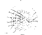
The cross-sectional view of Fig. 1 for getting perpendicular to the fiber axis of prior art microstructured optical fibers.
The cross-sectional view of Fig. 2 for getting perpendicular to the fiber axis of microstructured optical fibers of the present invention.
Fig. 3-5 is the curve of the various optic fibre characteristics of each optical fiber in expression the present invention and the prior art.
The cross-sectional view of Fig. 6 for getting perpendicular to the fiber axis of second embodiment of the invention microstructured optical fibers.
Fig. 7 represents the chromatic dispersion of optical fiber 1a shown in Figure 6 and the curve of mode field diameter (MFD).
The cross-sectional view of Fig. 8 for getting perpendicular to the fiber axis of third embodiment of the invention microstructured optical fibers.
Fig. 9-11 is expression and the various optic fibre characteristics of the corresponding optical fiber structure of Fig. 8 embodiment and the correlation curve of other optical fiber structures.
Figure 12 illustrates the method for prefabricated rods constructed in accordance.
Figure 13 explanation draws the method for prefabricated rods according to the present invention.
Figure 14 explanation draws the another kind of method of prefabricated rods according to the present invention.
The prefabricated rods that Figure 15 explanation is made according to another embodiment of the present invention.
Embodiment
Fig. 2 represents the xsect of first embodiment of the invention optical fiber 1, wherein is provided with a plurality of holes 3 in the quartz glass 2 as main medium, as secondary areas of dielectric.This xsect has interior zone 11 and centers on the perimeter 12 of this interior zone.The arrangement in hole is essentially hexagonal grid.Externally in the zone, the center in hole 32 overlaps with outside lattice point 42 substantially, and outside lattice point 42 is the part of the lattice point 4 in the hexagonal grid, and is in the perimeter.On the other hand, in interior zone, the center in hole 31 is outwards departed from inner lattice point 41 and is approximately 0.1 grid cycle.Inner lattice point is the part of the lattice point 4 in the hexagonal grid, and is in the interior zone.Diameter in xsect mesopore 31 and 32 is basic identical.For each grid cell of lattice point 41 or 42, single hole 31 or 32 center are in this unit.Describing when of the present invention, will be in hole in the grid cell of a lattice point and be called hole corresponding to this lattice point.
In addition, the overcoat zone 13 formed by quartz glass, perimeter centers on.Though for the guiding in the fiber cores, this overcoat zone is not requisite for light wave, but it can improve the physical strength of optical fiber, and reduces microbend loss, and microbend loss is a reason that causes loss.Because the arrangement in top described hole, the area of main areas of dielectric 21 between interior zone 11 mesopores 31 is greater than the area of main areas of dielectric 22 between 12 mesopores 32 of perimeter.As a result, the mean refractive index of interior zone is higher than the perimeter, light wave might be limited in the main areas of dielectric 21 in the interior zone 11 by total reflection, and on optical fiber the light conducting ripple.
At three kinds of structure: ha8 of the present invention, ha7 and ha6, and three kinds of structure hb8 of prior art, hb7 and hb6 have studied optical characteristics.Provided the relative aperture of these structures in the following table.
Table 1
| Code name | ha6 | ha7 | ha8 | hb6 | hb7 | hb8 |
| Relative aperture | 0.6 | 0.7 | 0.8 | 0.6 | 0.7 | 0.8 |
Under study for action, the diameter in hole is changed, and other size in the optical fiber also changes pro rata.
The multiple optic fibre characteristic of listed each optical fiber of Fig. 3-5 expression.Fig. 3 represents that the diameter with the hole is a function, the chromatic dispersion under the 1550nm wavelength.As shown in the figure, relative aperture increases the bore dia increase that causes can obtaining zero or negative dispersion under it.Compare with the prior art optical fiber with identical relative aperture, optical fiber of the present invention can obtain zero or negative dispersion under it bore dia is bigger.Fig. 4 represents that the diameter with the hole is a function, the chromatic dispersion gradient under the 1550nm wavelength.As shown in the figure, relative aperture increases the bore dia increase that causes can obtaining zero or negative dispersion slope under it.Compare with the prior art with identical relative aperture, optical fiber of the present invention can obtain zero or negative dispersion slope under it bore dia is bigger.Fig. 5 represents that the diameter with the hole is a function, the effective core area under the 1550nm wavelength.As shown in the figure, relative aperture increase cause under it, can obtaining little (less than 5 μ m
2) the effectively bore dia increase of core area.Compare with the prior art with identical relative aperture, optical fiber of the present invention can obtain little (less than 5 μ m under it
2) the effectively bore dia increase of core area.These curve shows the advantage that exists of optical fiber of the present invention.
Preferably will add in the interior zone 11 in the main medium in the main areas of dielectric 21, and reduce wherein viscosity such as the impurity of germanium or fluorine.As a result, might reduce the aggregation extent of main areas of dielectric drawing tension in the interior zone, the light wave that is conducted is limited in wherein, reduces to remain the excessive loss that tension force causes.Preferably the germanium with 1-35 mole % adds the main medium in the main areas of dielectric 21 in the interior zone 11, forms fiber grating by optical fiber being exposed to the open air in UV radiation lower edge fiber length change refractive index.As a result, might obtain wavelength selectivity transmission and wavelength selectivity directional coupler.Preferably change cross-sectional structure along fiber length.As a result, might change chromatic dispersion, and form the controlled transmission line of chromatic dispersion along fiber length.Be preferably formed as the part that does not wherein comprise the hole of certain-length.By form this part at optical fiber end, might prevent that pollutant from entering in the hole.Preferably adopt prescription glass (compound glass) or polymkeric substance as main medium, perhaps with gas or metal filled hole with light amplification.As a result, might strengthen the efficient of nonlinear optical effect, and/or realize optical amplification function.
Fig. 6 represents the xsect of the optical fiber 1a of second embodiment of the invention.In this structure, in quartz glass 2a, be arranged with a plurality of hole 3a, and the hole 32a among the 12a of perimeter is arranged to its center to be overlapped with corresponding lattice point 42a, lattice point 42a is the part of the lattice point 4a of hexagonal grid, and be in the perimeter, thereby this arrangement has the two-dimension translational symmetry.Can use other media to replace the hole with suitable refractive index.Because the two-dimension translational symmetry, might light wave be limited among the interior zone 11a by Bragg reflection, and on optical fiber the light conducting ripple.Because externally the arrangement of regional 12a mesopore 32a is periodic, so by Bragg reflection, perimeter 12a can reflect the light wave of certain frequency scope and propagation constant.Though this light wave can not be propagated among the externally regional 12a, owing to the structural cycle among the interior zone 11a is broken, so light wave limits and is transmitted among the interior zone 11a.
People such as Stig E.Barkou are at OFC ' 99FG5, and people such as J.A.West have described in ECOC ' 01Th.A.2.2 and have been known as by the Bragg reflection guiding, or the Waveguide Mechanism by the photon band gap guiding.But, the open of these prior aries do not recognized, might break structural cycle by allowing the hole depart from corresponding lattice point.As a result, although J.A.West has disclosed the chromatic dispersion with positive dispersion slope, but it is still unknown by the people to have a chromatic dispersion of negative dispersion slope.In the present invention, form the zone that light wave conducts therein, realize chromatic dispersion with negative dispersion slope by allowing the hole depart from corresponding lattice point.Fig. 7 represents chromatic dispersion and the mode field diameter (MFD) of optical fiber 1a shown in Figure 6.In this example, the pitch of hexagonal grid is 1.68 μ m, and the diameter in hole is 0.84 μ m.Hole 35a among the interior zone 11a, being in internally, lattice point 41a outwards is 0.15 grid cycle place.The hole 31a of interior zone 11a center is in inner lattice point 41a place.As in this embodiment, in interior zone, be centered close to the hole on the corresponding lattice point except forming it, preferably also form the hole of the corresponding lattice point of its misalignment.
As shown in Figure 7,1540nm is limited among the interior zone 11a to the light wave of 1570nm wavelength, and has little mode field diameter (MFD).In addition, in this wavelength coverage, chromatic dispersion gradient is for negative, and this is favourable for the application of compensation positive slope chromatic dispersion.Also can because Bragg reflection takes place, thereby can realize depending on the transmission of wavelength in limited frequency range with optical fiber 1a as bandpass filter.
Fig. 8 represents the xsect of third embodiment of the invention optical fiber 1c.In optical fiber 1c, in quartz glass 2c, be arranged with a plurality of hole 3c.Has interior zone 11c in the xsect and around the perimeter 12c of this interior zone.In this embodiment, the arrangement in hole is essentially square grid.Among the externally regional 12c, the center of hole 32c is in outside lattice point 42c place, the part of the lattice point 4c that outside lattice point 42c is a square grid, and be among the 12c of perimeter.On the other hand, in interior zone 11c, about 0.1 grid cycle of inner lattice point 41c is outwards departed from the center of hole 31c.Inner lattice point 41c is the part of the lattice point 4c in the positive dirction grid, and is among the interior zone 11c.For each grid cell of lattice point 41c or 42c, the center of single hole 31c or 32c is in this unit.In addition, perimeter 12c is centered on by overcoat zone 13c.Though overcoat zone 13c is also inessential for waveguide, but it has the effect that increases optical fiber 1c physical strength and reduce microbend loss, and microbend loss is a reason that causes loss.
Because the arrangement in top described hole, the area of main areas of dielectric 21c between the interior zone 11c mesopore 31c is greater than the area of main areas of dielectric 22c between the 12c mesopore 32c of perimeter.As a result, the mean refractive index of interior zone is higher than the perimeter, light wave might be limited in the main areas of dielectric 21c among the interior zone 11c by total reflection, and on optical fiber the light conducting ripple.
The optical fiber that relatively has all structures as shown in Figure 8 overlaps with all lattice points in the square grid basically with the center, hole, thereby but lack the optical characteristics of the microstructured optical fibers of the projecting zone leveling refractive index of center, hole mean refractive index at the fiber optic hub place, study.Provided relative aperture in the following table, structure ra8 wherein, optical fiber structure of the present invention shown in ra7 and the ra6 representative graph 8; On behalf of hole and grid, structure rb8, rb7 and rb6 do not depart from.
Table 2
| Code name | ra6 | ra7 | ra8 | rb6 | rb7 | rb8 |
| Relative aperture | 0.6 | 0.7 | 0.8 | 0.6 | 0.7 | 0.8 |
In this research, the diameter in hole is changed, and other size in the optical fiber also changes pro rata.
The various optic fibre characteristics of listed each optical fiber of Fig. 9-11 expression.Fig. 9 represents that the diameter with the hole is a function, the chromatic dispersion under the 1550nm wavelength.As shown in the figure, relative aperture increases the bore dia increase that causes can obtaining zero or negative dispersion under it.Compare with other optical fiber with identical relative aperture, optical fiber of the present invention under it, can obtain zero or the diameter in the hole of negative dispersion bigger.Figure 10 represents that the diameter with the hole is a function, the chromatic dispersion gradient under the 1550nm wavelength.As shown in the figure, relative aperture increases the bore dia increase that causes can obtaining zero or negative dispersion slope under it.Compare with other optical fiber with identical relative aperture, optical fiber of the present invention under it, can obtain zero or the diameter in the hole of negative dispersion slope bigger.Figure 11 represents that the diameter with the hole is a function, the effective core area under the 1550nm wavelength.As shown in the figure, relative aperture increase cause under it, can obtaining little (less than 5 or 6 μ m
2) the effectively bore dia increase of core area.Compare with other optical fiber with identical relative aperture, optical fiber of the present invention can obtain little (less than 5 or 6 μ m under it
2) the effectively diameter increase in the hole of core area.These curve shows the advantage that exists of optical fiber of the present invention.
Can make the optical fiber of the invention described above embodiment as shown in figure 12.At first, by well-known method,, make the cylindrical prefabricated rods of making by quartz glass as VAD method, MCVD method and OVD method.The quartz glass that is used for prefabricated rods can not have impurity, perhaps can comprise such as germanium, fluorine, chlorine, boron, aluminium, phosphorus the alloy of rare earth element and transition metal.By the kind and the concentration of suitable selection alloy, might strengthen the efficient of nonlinear optical effect, perhaps realize light amplifying characteristic.
The second, in the prefabricated rods 61 of fixing, form a plurality of holes 64 of extending by drilling equipment 63 along the prefabricated rods length direction by grabbing device 62.Make the arrangement and the Fig. 2 in hole, the arrangement of the optical fiber mesopore that will make shown in 6 and 8 matches.Preferably the end 65 of drilling equipment 63 is made by the alloy that comprises diamond particles, and perhaps the metal that has a diamond particles by the surface is made.Preferably improve drilling efficiency by ultrasound wave being imposed on drilling equipment 63.Though hole 64 can penetrate prefabricated rods, but also may end the hole, handle thereby sufficiently long original preform rod can be given over to subsequent step at place, prefabricated rods centre position.Shorten the time that boring length has also shortened the boring step.Can be by axle rotary drilling device 63 around hole 64, perhaps around the axle rotation prefabricated rods 61 in hole 64, perhaps rotary drilling device and prefabricated rods and drilling bore hole 64 simultaneously.
After the boring step, further treatment step comprises and elongates prefabricated rods 61, and the prefabricated rods 61 of being elongated is inserted in the glass tube that internal diameters are a bit larger tham the institute's prefabricated rods of elongating 61 external diameters, heat and with the glass tube flattening on the prefabricated rods 61 of being elongated.And, can be on the outside surface of prefabricated rods 61 by gas deposition with the quartz glass ash deposition, and the ash that deposited of heating and sintering.By adopting these steps, might reduce the diameter in hole and the ratio of whole prefabricated rods diameter, form the small diameter bore that is difficult to form by boring equivalently.
Also may pass through hydrofluorite or SF
6The inside surface in gas etch hole 64.As a result, might remove the surface and go up or,, and reduce surfaceness, produce the low transmission loss as hydroxyl and transition metal near the impurity in the glass on surface.
At last, with prefabricated rods 61 drawing optic fibres, as shown in figure 13.Grasp prefabricated rods 61 with the grabbing device (not shown).The end that prefabricated rods 61 has hole 64 links to each other with pressure adjustment assembly 72 by coupling arrangement 71, thus the pressure in the adjustment hole 64.The arrangement in hole is identical with the arrangement in manufacturing step of prefabricated rods shown in Figure 12 or following hole shown in Figure 15 or suitable.From the other end, prefabricated rods is transported in the heating arrangement 73 at a predetermined velocity.From heating and softening prefabricated rods part drawing optical fiber 76.With draw-gear (not shown) traction optical fiber.Can control the diameter of optical fiber mesopore by the pressure of controlled pressure regulating device 72.
Also may be from the hole 64 sealed prefabricated rods 61 drawing optical fibers, as shown in figure 14.As a result, be easy to prevent that pollutant from entering in the hole 64.The arrangement in hole is identical or suitable with the arrangement of the manufacturing step of prefabricated rods shown in Figure 12 or Figure 15 mesopore given below.
Also may in prefabricated rods 61, not form hole 64 as shown in figure 12 by boring.Figure 15 illustrates and uses several different materials to make prefabricated rods, to obtain optical fiber.A branch of by a plurality of quartz capillaries 67 are arranged to around quartz pushrod 66, and should restraint and insert in the quartz socket tube 68, prefabricated rods 61a can be formed.The diameter of quartz pushrod 66 is less than the diameter of quartz capillary 67.Then, in step shown in Figure 13 or 14, draw this prefabricated rods 61a.Select to draw temperature, make surface tension shrink and/or sealing quartz capillary 67 between the space.Owing to have part at quartz pushrod 66, the flow of soften glass is very little during gap constrictions, so the distance between the hole is greater than other positions in the cross section.As a result, can obtain the similar optical fiber of xsect and embodiment 1.
The prefabricated stick producing method method of Figure 15 is suitable for using several different materials to make optical fiber.For example, have greater than the quartz of 10% germanium material, can strengthen the efficient of nonlinear optical effect as quartz pushrod 66 by use.And, be mixed with the quartz pushrod 66 of rare earth element by employing, can obtain to have the optical fiber of light amplification.
Though in conjunction with think the most practical at present and illustrated embodiments invention has been described, but the invention is not restricted to the disclosed embodiments, on the contrary, be intended to comprise multiple modification included in the claims spirit and scope and equivalence arrangement.
Claims (17)
1. optical fiber comprises:
Have predetermined refraction main medium and
A plurality of holes, hole have the refractive index that is different from main medium, and are arranged in the main areas of dielectric along at least a portion fiber lengths, to be divided into interior zone and around the perimeter of this interior zone, wherein:
Can determine translation symmetry grid in the xsect of described a part of optical fiber, the center in each hole overlaps with corresponding grid lattice point in the perimeter, and the corresponding grid lattice point of the misalignment in a plurality of holes in the interior zone.
2. optical fiber as claimed in claim 1, wherein this interior zone comprises that mean refractive index is higher than the core zone of perimeter mean refractive index.
3. optical fiber as claimed in claim 1, wherein the index distribution in this perimeter has the two-dimension translational symmetry in xsect, to support the waveguide mode by Bragg reflection was guided.
4. optical fiber as claimed in claim 2, wherein this main medium is pure or doped silica glass, the hole is filled the gas with predetermined pressure.
5. optical fiber as claimed in claim 3, wherein this main medium is pure or doped silica glass, the hole is filled the gas with predetermined pressure.
6. optical fiber as claimed in claim 4 is wherein with at least 1 mole of %GeO
2Mix at least a portion master medium.
7. optical fiber as claimed in claim 1, wherein the sectional area at the xsect mesopore is identical.
8. optical fiber as claimed in claim 1, wherein:
This translation symmetry grid is a hexagonal grid,
This interior zone comprises three inner grid lattice points, is three summits of the length of side equilateral triangle that equals grid cycle, and
This equilateral triangle circumscribed circle outside that is centered close to these three the corresponding holes of inner grid lattice point.
9. optical fiber as claimed in claim 1, wherein:
This translation symmetry grid is a square grid,
This interior zone comprises four inner grid lattice points, is foursquare four summits that a length of side equals grid cycle,
This square circumscribed circle outside that is centered close to these four the corresponding holes of inner grid lattice point.
10. optical fiber as claimed in claim 1, wherein the minimum profile curvature radius in this hole is more than or equal to 1.2 μ m, and is less than or equal to zero at 1280nm to the chromatic dispersion under the 1800nm predetermined wavelength.
11. optical fiber as claimed in claim 1, wherein the minimum profile curvature radius in this hole is more than or equal to 1.7 μ m, and the chromatic dispersion gradient under the wavelength of 1550nm is less than or equal to zero.
12. optical fiber as claimed in claim 1, wherein the minimum profile curvature radius in this hole is more than or equal to 2.0 μ m, and the effective core area under the wavelength of 1550nm is less than the twice of wavelength square.
13. a method of making optical fiber may further comprise the steps:
Make preform, this preform comprises main medium and a plurality of hole with second refractive index with first refractive index; And
Described prefabricated rods pulled into have an interior section and a segment length around the exterior section of described interior section, wherein can determine to have the grid of the translation symmetry of a plurality of grid lattice points, each grid lattice point overlaps with the center in a corresponding described hole in the perimeter, and the center of departing from respective aperture of at least a portion lattice point in the interior zone.
14. methods for optical fiber manufacture as claimed in claim 13 is being to form a plurality of holes in the preform made of main medium with quartz glass wherein.
15. methods for optical fiber manufacture as claimed in claim 14 is wherein with at least 1 mole of %GeO
2Mix at least a portion master medium.
16. methods for optical fiber manufacture as claimed in claim 13, wherein this manufacturing step comprises the excellent integrated bundle that kapillary that predetermined quantity is pre-determined internal diameter and external diameter by having of making of quartz glass and one or more diameter of being made by quartz glass are different from capillary diameter.
17. a method of making optical fiber may further comprise the steps:
Make preform, this preform comprises the main medium with first refractive index, with a plurality of holes with second refractive index, wherein can determine to have the grid of the translation symmetry of a plurality of lattice points, each grid lattice point overlaps with the center in a corresponding described hole in the perimeter, and the center that each the grid lattice point in the interior zone departs from respective aperture, described perimeter is around described interior zone; And
With described prefabricated rods pull into one section have with this prefabricated rods in the optical fiber in the proportional main areas of dielectric of respective regions and hole, thereby the relation between the lattice point of the center of retaining hole and this translation symmetry grid.
Applications Claiming Priority (2)
| Application Number | Priority Date | Filing Date | Title |
|---|---|---|---|
| JP083805/2002 | 2002-03-25 | ||
| JP2002083805A JP4158391B2 (en) | 2002-03-25 | 2002-03-25 | Optical fiber and manufacturing method thereof |
Publications (2)
| Publication Number | Publication Date |
|---|---|
| CN1447136A CN1447136A (en) | 2003-10-08 |
| CN1306294C true CN1306294C (en) | 2007-03-21 |
Family
ID=28035806
Family Applications (1)
| Application Number | Title | Priority Date | Filing Date |
|---|---|---|---|
| CNB031082335A Expired - Fee Related CN1306294C (en) | 2002-03-25 | 2003-03-25 | Microstructure optical fiber and its mfg. method |
Country Status (7)
| Country | Link |
|---|---|
| US (1) | US6850679B2 (en) |
| EP (1) | EP1351077B1 (en) |
| JP (1) | JP4158391B2 (en) |
| KR (1) | KR100963812B1 (en) |
| CN (1) | CN1306294C (en) |
| DE (1) | DE60302599T2 (en) |
| DK (1) | DK1351077T3 (en) |
Families Citing this family (17)
| Publication number | Priority date | Publication date | Assignee | Title |
|---|---|---|---|---|
| US7054513B2 (en) * | 2003-06-09 | 2006-05-30 | Virginia Tech Intellectual Properties, Inc. | Optical fiber with quantum dots |
| US7079309B1 (en) * | 2003-06-25 | 2006-07-18 | Sandia Corporation | Use of a photonic crystal for optical amplifier gain control |
| JP2006126725A (en) * | 2004-11-01 | 2006-05-18 | Sumitomo Electric Ind Ltd | Optical fiber |
| JP5170852B2 (en) * | 2005-09-29 | 2013-03-27 | 古河電気工業株式会社 | Optical fiber and optical transmission medium |
| EP1939656B1 (en) * | 2005-09-29 | 2019-10-23 | The Furukawa Electric Co., Ltd. | Optical fiber and optical transmission medium |
| US7793521B2 (en) * | 2006-03-01 | 2010-09-14 | Corning Incorporated | Method enabling dual pressure control within fiber preform during fiber fabrication |
| US8755658B2 (en) * | 2007-02-15 | 2014-06-17 | Institut National D'optique | Archimedean-lattice microstructured optical fiber |
| JP2009015294A (en) * | 2007-06-05 | 2009-01-22 | Furukawa Electric Co Ltd:The | Holey fiber, and method for manufacturing holey fiber |
| DE102007033086A1 (en) * | 2007-07-15 | 2009-01-29 | Heraeus Quarzglas Gmbh & Co. Kg | Method for producing an optical component with longitudinal bores, and microstructured optical fiber |
| EP2585863B1 (en) * | 2010-06-25 | 2018-10-03 | NKT Photonics A/S | Large core area single mode optical fiber |
| JP5503453B2 (en) * | 2010-08-09 | 2014-05-28 | 古河電気工業株式会社 | OPTICAL FIBER BASE MATERIAL MANUFACTURING METHOD, HOLE STRUCTURE OPTICAL FIBER MANUFACTURING METHOD, AND PRESSURE / PRESSURE CONNECTOR |
| JP6281869B2 (en) * | 2014-02-27 | 2018-02-21 | 国立大学法人大阪大学 | Directional coupler and multiplexer / demultiplexer devices |
| JP6402466B2 (en) * | 2014-03-31 | 2018-10-10 | 住友電気工業株式会社 | Multi-core optical fiber manufacturing method |
| JP6770358B2 (en) * | 2016-07-13 | 2020-10-14 | 太平洋精工株式会社 | Multiple fuse |
| JP7132008B2 (en) * | 2018-07-19 | 2022-09-06 | 矢崎総業株式会社 | Thermoacoustic device stack manufacturing method and thermoacoustic device stack manufacturing apparatus |
| CN109020185B (en) * | 2018-08-03 | 2021-05-28 | 长飞光纤光缆股份有限公司 | Method for preparing microstructure optical fiber prefabricated rod |
| CN111069778B (en) * | 2018-10-18 | 2020-12-15 | 清华大学 | Method and system for generating microstructure in optical fiber |
Citations (4)
| Publication number | Priority date | Publication date | Assignee | Title |
|---|---|---|---|---|
| WO1999064903A1 (en) * | 1998-06-09 | 1999-12-16 | Crystal Fibre A/S | Microstructured optical fibres |
| US6097870A (en) * | 1999-05-17 | 2000-08-01 | Lucent Technologies Inc. | Article utilizing optical waveguides with anomalous dispersion at vis-nir wavelenghts |
| CN1269020A (en) * | 1997-06-26 | 2000-10-04 | 英国国防部 | Single mode optical fiber |
| CN1331808A (en) * | 1998-12-21 | 2002-01-16 | 康宁股份有限公司 | Photonic crystal fiber |
Family Cites Families (5)
| Publication number | Priority date | Publication date | Assignee | Title |
|---|---|---|---|---|
| EP1340725B1 (en) * | 1999-02-19 | 2006-01-25 | Crystal Fibre A/S | Method of producing a photonic crystal fibre |
| WO2002012931A2 (en) * | 2000-07-21 | 2002-02-14 | Crystal Fibre A/S | Dispersion manipulating fibre |
| JP3836730B2 (en) | 2002-01-29 | 2006-10-25 | 三菱電線工業株式会社 | Polarization-maintaining photonic crystal fiber and manufacturing method thereof |
| JP2004177817A (en) * | 2002-11-28 | 2004-06-24 | Sumitomo Electric Ind Ltd | Optical fiber and optical module |
| JP2004240390A (en) * | 2002-12-10 | 2004-08-26 | Sumitomo Electric Ind Ltd | Optical fiber |
-
2002
- 2002-03-25 JP JP2002083805A patent/JP4158391B2/en not_active Expired - Fee Related
-
2003
- 2003-03-20 US US10/391,754 patent/US6850679B2/en not_active Expired - Fee Related
- 2003-03-24 EP EP03006701A patent/EP1351077B1/en not_active Expired - Fee Related
- 2003-03-24 DK DK03006701T patent/DK1351077T3/en active
- 2003-03-24 DE DE60302599T patent/DE60302599T2/en not_active Expired - Lifetime
- 2003-03-24 KR KR1020030018087A patent/KR100963812B1/en not_active IP Right Cessation
- 2003-03-25 CN CNB031082335A patent/CN1306294C/en not_active Expired - Fee Related
Patent Citations (4)
| Publication number | Priority date | Publication date | Assignee | Title |
|---|---|---|---|---|
| CN1269020A (en) * | 1997-06-26 | 2000-10-04 | 英国国防部 | Single mode optical fiber |
| WO1999064903A1 (en) * | 1998-06-09 | 1999-12-16 | Crystal Fibre A/S | Microstructured optical fibres |
| CN1331808A (en) * | 1998-12-21 | 2002-01-16 | 康宁股份有限公司 | Photonic crystal fiber |
| US6097870A (en) * | 1999-05-17 | 2000-08-01 | Lucent Technologies Inc. | Article utilizing optical waveguides with anomalous dispersion at vis-nir wavelenghts |
Also Published As
| Publication number | Publication date |
|---|---|
| DK1351077T3 (en) | 2006-03-27 |
| EP1351077A2 (en) | 2003-10-08 |
| KR100963812B1 (en) | 2010-06-16 |
| DE60302599T2 (en) | 2006-08-10 |
| CN1447136A (en) | 2003-10-08 |
| JP4158391B2 (en) | 2008-10-01 |
| EP1351077A3 (en) | 2004-01-07 |
| US20030180018A1 (en) | 2003-09-25 |
| JP2003277090A (en) | 2003-10-02 |
| AU2003203280A1 (en) | 2003-10-16 |
| US6850679B2 (en) | 2005-02-01 |
| KR20030077396A (en) | 2003-10-01 |
| DE60302599D1 (en) | 2006-01-12 |
| EP1351077B1 (en) | 2005-12-07 |
Similar Documents
| Publication | Publication Date | Title |
|---|---|---|
| CN1306294C (en) | Microstructure optical fiber and its mfg. method | |
| JP4465527B2 (en) | Microstructured optical fiber, preform, and manufacturing method of microstructured optical fiber | |
| CN108919417B (en) | Hollow photonic band gap fiber based on isolation anti-resonance layer | |
| US20200379168A1 (en) | Multi-core fibers and method of manufacturing the same, and optical transmission system and optical transmission method | |
| CN1891649A (en) | Low loss optical fiber designs and methods for their manufacture | |
| US20060018614A1 (en) | High performance dispersion compensating optical fibers and manufacturing method for the same | |
| CN1331808A (en) | Photonic crystal fiber | |
| US20040050110A1 (en) | Methods for fabricating optical fibers and optical fiber preforms | |
| CN111443419B (en) | Large-mode-field bending-resistant multi-core few-mode optical fiber | |
| CN1300607C (en) | Bending insensitive optical fiber and preparing method thereof | |
| CN1429348A (en) | Optical fiber | |
| US7769263B1 (en) | Optical fiber and a method for making such | |
| CN1564034A (en) | Double-refraction microstructure optical fiber and its mfg. method | |
| JP4015959B2 (en) | High stress-resistant optical fiber | |
| KR100660148B1 (en) | Manufacturing Method for Optical Fiber Having Air-Holes | |
| KR100782475B1 (en) | The Method of Optical Fiber and Optical Fiber thereof | |
| JP3917115B2 (en) | Optical fiber manufacturing method | |
| JP3866696B2 (en) | Optical fiber manufacturing method | |
| JP2004226540A (en) | High stress resistant optical fiber | |
| CN1447929A (en) | Holey optical fibres | |
| CN114675368A (en) | Photonic crystal fiber and preparation method thereof | |
| US20060008218A1 (en) | Method of manufacturing an optical fibre, a preform and an optical fibre | |
| KR100795217B1 (en) | The Method of Manufacturing Optical Fiber for Dispersion Management | |
| JP2005022943A (en) | Method for manufacturing optical fiber |
Legal Events
| Date | Code | Title | Description |
|---|---|---|---|
| C06 | Publication | ||
| PB01 | Publication | ||
| C10 | Entry into substantive examination | ||
| SE01 | Entry into force of request for substantive examination | ||
| C14 | Grant of patent or utility model | ||
| GR01 | Patent grant | ||
| CF01 | Termination of patent right due to non-payment of annual fee |
Granted publication date: 20070321 Termination date: 20150325 |
|
| EXPY | Termination of patent right or utility model |