CN1302209C - Disc brake - Google Patents
Disc brake Download PDFInfo
- Publication number
- CN1302209C CN1302209C CNB021584486A CN02158448A CN1302209C CN 1302209 C CN1302209 C CN 1302209C CN B021584486 A CNB021584486 A CN B021584486A CN 02158448 A CN02158448 A CN 02158448A CN 1302209 C CN1302209 C CN 1302209C
- Authority
- CN
- China
- Prior art keywords
- disk
- rotation
- sense
- mounting holes
- bolt mounting
- Prior art date
- Legal status (The legal status is an assumption and is not a legal conclusion. Google has not performed a legal analysis and makes no representation as to the accuracy of the status listed.)
- Expired - Fee Related
Links
Images


Classifications
-
- F—MECHANICAL ENGINEERING; LIGHTING; HEATING; WEAPONS; BLASTING
- F16—ENGINEERING ELEMENTS AND UNITS; GENERAL MEASURES FOR PRODUCING AND MAINTAINING EFFECTIVE FUNCTIONING OF MACHINES OR INSTALLATIONS; THERMAL INSULATION IN GENERAL
- F16D—COUPLINGS FOR TRANSMITTING ROTATION; CLUTCHES; BRAKES
- F16D55/00—Brakes with substantially-radial braking surfaces pressed together in axial direction, e.g. disc brakes
- F16D55/02—Brakes with substantially-radial braking surfaces pressed together in axial direction, e.g. disc brakes with axially-movable discs or pads pressed against axially-located rotating members
- F16D55/22—Brakes with substantially-radial braking surfaces pressed together in axial direction, e.g. disc brakes with axially-movable discs or pads pressed against axially-located rotating members by clamping an axially-located rotating disc between movable braking members, e.g. movable brake discs or brake pads
- F16D55/224—Brakes with substantially-radial braking surfaces pressed together in axial direction, e.g. disc brakes with axially-movable discs or pads pressed against axially-located rotating members by clamping an axially-located rotating disc between movable braking members, e.g. movable brake discs or brake pads with a common actuating member for the braking members
-
- F—MECHANICAL ENGINEERING; LIGHTING; HEATING; WEAPONS; BLASTING
- F16—ENGINEERING ELEMENTS AND UNITS; GENERAL MEASURES FOR PRODUCING AND MAINTAINING EFFECTIVE FUNCTIONING OF MACHINES OR INSTALLATIONS; THERMAL INSULATION IN GENERAL
- F16D—COUPLINGS FOR TRANSMITTING ROTATION; CLUTCHES; BRAKES
- F16D55/00—Brakes with substantially-radial braking surfaces pressed together in axial direction, e.g. disc brakes
- F16D55/02—Brakes with substantially-radial braking surfaces pressed together in axial direction, e.g. disc brakes with axially-movable discs or pads pressed against axially-located rotating members
- F16D55/22—Brakes with substantially-radial braking surfaces pressed together in axial direction, e.g. disc brakes with axially-movable discs or pads pressed against axially-located rotating members by clamping an axially-located rotating disc between movable braking members, e.g. movable brake discs or brake pads
- F16D55/228—Brakes with substantially-radial braking surfaces pressed together in axial direction, e.g. disc brakes with axially-movable discs or pads pressed against axially-located rotating members by clamping an axially-located rotating disc between movable braking members, e.g. movable brake discs or brake pads with a separate actuating member for each side
-
- F—MECHANICAL ENGINEERING; LIGHTING; HEATING; WEAPONS; BLASTING
- F16—ENGINEERING ELEMENTS AND UNITS; GENERAL MEASURES FOR PRODUCING AND MAINTAINING EFFECTIVE FUNCTIONING OF MACHINES OR INSTALLATIONS; THERMAL INSULATION IN GENERAL
- F16D—COUPLINGS FOR TRANSMITTING ROTATION; CLUTCHES; BRAKES
- F16D55/00—Brakes with substantially-radial braking surfaces pressed together in axial direction, e.g. disc brakes
- F16D2055/0075—Constructional features of axially engaged brakes
- F16D2055/0091—Plural actuators arranged side by side on the same side of the rotor
-
- F—MECHANICAL ENGINEERING; LIGHTING; HEATING; WEAPONS; BLASTING
- F16—ENGINEERING ELEMENTS AND UNITS; GENERAL MEASURES FOR PRODUCING AND MAINTAINING EFFECTIVE FUNCTIONING OF MACHINES OR INSTALLATIONS; THERMAL INSULATION IN GENERAL
- F16D—COUPLINGS FOR TRANSMITTING ROTATION; CLUTCHES; BRAKES
- F16D2121/00—Type of actuator operation force
- F16D2121/02—Fluid pressure
Landscapes
- Engineering & Computer Science (AREA)
- General Engineering & Computer Science (AREA)
- Mechanical Engineering (AREA)
- Braking Arrangements (AREA)
Abstract
The invention provides a disc brake capable of suppressing an increase in the number of parts, upsizing, and deformation by brake torque, besides saving width in the disc rotational direction of a brake pad to ensure enough brake performance. This disc brake is a radial mount type in which a caliper 13 is fixed to a support member by screwing mount bolts into two bolt mounting holes 34a, 34b disposed along a disc radial direction to be separated in a disc rotational direction. In the caliper, a communicating passage 36 is disposed between the bolt mounting hole 34b on the outlet side in the disc rotational direction and the brake pad 17, and the central position C2 in the disc rotational direction of the brake pad 17 is disposed at off-set position to the central position C1 between the bolt mounting holes 34a, 34b separated in the disc rotational direction.
Description
Technical field
The present invention relates to the car brakeing disk type braker, particularly relate to the clamp radially mount type disk type braker that is supported on vehicle body side along the bolt of disc radius direction.
Background technique
As shown in Figure 6, comprise in the disk type braker: disk 101; A pair of brake block 102, it is provided in its both sides to coordinate the state of coupling in the position of disk sense of rotation (left and right directions among Fig. 6) along disk 101 axial directions (direction about among Fig. 6); Clamp 105, its with coordinate coupling the state of the position of disk sense of rotation, be provided in its both sides along the disk axis and be separated along the disk direction and set, its inside have two pairs can chimeric slidably pushing brake block 102 the 103a of cylinder chamber, the 103b of piston 104a, 104b; Supporting part, it is not (it illustrates) of vehicle body side stationary clamp 105.
This disk clamp its 105 along disc radius direction and parallel to each other, simultaneously by two the bolt mounting holes 107a of configuration that are separated in the disk sense of rotation, construction bolt is fixed on the supporting part and is radially mount type among the 107b.
Then, for the circulation of brake fluid,, be communicated with a pair of 103a of cylinder chamber, the 103b at disk sense of rotation outlet side of clamp 105 by the access 108 that between the bolt mounting holes 107b of disk sense of rotation outlet side and brake block 102, is provided with.In addition, also be communicated with at the adjacent 103b of cylinder chamber of disk sense of rotation with intermediate connection road 109.
As existing radially mount type disk type braker, make its middle position between bolt mounting holes 107a, the 107b of disk sense of rotation, at the middle position of the brake block 102 of disk sense of rotation and the middle position between piston 104a, the 104b in the disk sense of rotation all on the same position shown in symbol C11.
In the clamp 105 of as described radially mount type disk type braker, be necessary to form bolt mounting holes 107a, 107b along the disc radius direction, be necessary to form access 108 in the hands-off position of bolt mounting holes 107b, and be to set brake block 102 to be necessary space portion 110 to be set in the position of not interfering this path 108 with disk sense of rotation outlet side.Therefore, as shown in Figure 6,, do not expand the distance L 11 between bolt mounting holes 107a, 107b and the disk 101, and shorten bolt mounting holes 107a, the distance of 107b between the disk sense of rotation in order to realize clamp 105 miniaturizations.Like this, the amplitude L13 in the disk sense of rotation of brake block 102 will shorten, and braking ability may occur and reduce.
In addition, as shown in Figure 7, do not expand bolt mounting holes 107a, the distance L 11 of 107b and disk 101, and in order to ensure sufficient braking ability, just want to expand the amplitude L13 of brake block 102 in the disk sense of rotation, the space portion 110 that sets this brake block 102 is also expanded in the disk sense of rotation, when avoiding interfering, form access 108 and bolt mounting holes 107b, will be offset bolt mounting holes 107 in order to space out in the disk sense of rotation, 107b, its result, bolt mounting holes 107a, the interval L12 of 107b is strengthened, and makes clamp 105 become big.
Have again, as shown in Figure 8, expand the width of cloth L13 in the disk sense of rotation of brake block 102 in order to ensure sufficient braking ability, also to suppress the maximization of clamp 105 simultaneously, will suppress the expansion of the interval L12 of bolt hole 107a, 107b in the disk sense of rotation, like this, the distance L 11 of bolt mounting holes 107a, 107b and disk 101 is widened, as a result, the distance of disk 101 and bolt mounting holes 107a, 107b is elongated, and clamp 105 is increased by the distortion that moment of rotation produces.
In addition, open as shown in the 2000-249173 communique, also can be formed in the clamp outside connecting tube structure that forms path is installed, but this occasion certainly will increase the part number, and cost is increased as the spy.
Summary of the invention
The purpose of this invention is to provide a kind of disk type braker, this disk type braker is guaranteed guaranteeing sufficient braking ability can suppress the increase of part number and size in the fabric width of disk sense of rotation of brake block, and can suppress the distortion that produced by braking moment.
In order to reach described purpose, disk type braker of the present invention comprises: to coordinate a pair of brake block of both sides that the state of coupling in the position of the sense of rotation of disk is provided in the axial direction of disk; In the both sides of the axial direction of disk relatively to the clamp of the cylinder chamber of the piston that forms the described brake block of chimeric slidably pushing; Fix the supporting part of this clamp at vehicle body side.Described clamp is to be fixed on radially mount type on the described supporting part along be separated by the sense of rotation at disk construction bolt in two bolt mounting holes that set of disc radius direction.In described clamp inside, only the inlet side of disk sense of rotation and a certain side in the outlet side, between described bolt mounting holes and described brake block, set be communicated with described relatively to the access of cylinder chamber, simultaneously, with described brake block at the middle position of disk sense of rotation with respect to these middle position of the described bolt mounting holes that is separatedly installed in the disk sense of rotation to being offset setting at the inlet side of disk sense of rotation and the opposing party in the outlet side.
Like this, because set to moving along a certain lateral deviation of disk sense of rotation at the middle position of the disk sense of rotation of brake block middle position with respect to the bolt mounting holes that is separatedly installed in the disk sense of rotation, this had just both guaranteed the amplitude in the disk sense of rotation of brake block, the connecting tube that forms access is installed in the outside that also not be used in clamp, need not expand the interval of the bolt mounting holes that is separated in the disk direction again, also need not expand the distance between bolt mounting holes and disk, can expand the bolt mounting holes of disk sense of rotation outlet side and the interval between the brake block again, can set access between hereinto in these mutual noninterference modes.
In addition, disk type braker of the present invention also comprises: be provided in the both sides of the axial direction of disk in couples to coordinate the state of coupling in the position of disk sense of rotation, simultaneously the disk sense of rotation be separated and set many to brake block; In the both sides of the axial direction of disk relatively to the clamp of the cylinder chamber of the piston that forms the described brake block of chimeric slidably pushing; Fix the supporting part of this clamp at vehicle body side.To be it be fixed on radially mount type clamp on the described supporting part along be separated by the sense of rotation at disk construction bolt in two bolt mounting holes that set of disc radius direction with described clamp.In described clamp inside, only in the inlet side of disk sense of rotation and the one side in the outlet side, between described bolt mounting holes and described brake block, set be communicated with described relatively to the access of cylinder chamber, simultaneously, described these brake blocks are arranged on skew along the inlet side of disk sense of rotation and the opposing party's side in the outlet side at middle position that the disk sense of rotation is separated with respect to the middle position of described these bolt mounting holes that are separatedly installed in the disk sense of rotation.
Like this, because the middle position of these brake blocks that will be separated in the disk sense of rotation, middle position with respect to these bolt mounting holes that are separatedly installed in the disk direction sets to moving along a certain lateral deviation of disk sense of rotation, this had just both guaranteed the amplitude in the disk sense of rotation of brake block, the connecting tube that forms access is installed in the outside that also not be used in clamp, need not expand the distance that also need not expand at the interval of the bolt mounting holes that the disk direction is separated between bolt mounting holes and disk again, can expand the interval between disk sense of rotation outlet side bolt mounting holes and the brake block again, can set access therebetween in these mutual noninterference modes.
Description of drawings
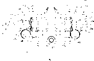
Fig. 1 represents the top plan view of the 1st embodiment's of the present invention disk type braker;
Fig. 2 represents the side view of the 1st embodiment's of the present invention disk type braker;
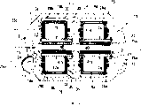
Fig. 3 represents the plan view of the 2nd embodiment's of the present invention disk type braker;
Fig. 4 represents the sectional drawing that the X-X line along among Fig. 2 of the 2nd embodiment's of the present invention disk type braker is cut open;
Fig. 5 represents the sectional side view of the 2nd embodiment's of the present invention disk type braker;
Fig. 6 represents the top plan view of disk type braker;
Fig. 7 represents the top plan view of disk type braker;
Fig. 8 represents the top plan view of disk type braker.
Embodiment
The 1st embodiment's of the present invention disk type braker seen figures.1.and.2 be described as follows.In addition, in the following description, the state that is installed in the desired location of vehicle body side with disk type braker describes.
The 1st embodiment's disk type braker 10 comprises: and the disk 11 of the wheel one of vehicle rotation; Disk 11 is adjacent at its axial direction and sets relatively, is installed in the supporting part 12 of vehicle body side; In (among Fig. 2 from bottom to top direction) outside of the radial direction of disk 11, be fixed on clamp 13 on the supporting part 12 with the state on this disk 11.When vehicle advanced, disk 11 was pressed the rotation of direction shown in the arrow R among Fig. 1 and Fig. 2.
At this, a pair of brake block 17, the liner 21 that metal holder 20 is arranged and stick respectively on 20 at metal becomes symmetry, is provided in the both sides of the axial direction of disk 11 to coordinate the state of coupling in the position of disk sense of rotation and disc radius direction mutually in the disk sense of rotation.
A pair of dividing body 23 forms joint 25a, the 25b of the connection dividing body 23 that has matching surface 24 respectively in the both sides of disk sense of rotation, simultaneously between the joint 25b of the joint 25a of disk sense of rotation inlet side and disk sense of rotation outlet side, it is more hollow at disk axis direction ratio matching surface 24 to form cylinder part 26.
Thereby, in each cylinder part 26 of clamp body 15, form to coordinate the state of coupling, two countercylinder chamber 28a, 28b that the both sides that mutual subtend is provided in the axial direction of disk in couples are separated and set in the disk sense of rotation simultaneously in the position of disk sense of rotation and disc radius direction.Just form with coordinate the state of coupling in the position of disk sense of rotation and disc radius direction be provided in disk 11 axial direction both sides disk sense of rotation inlet side a pair of 28a of cylinder chamber and to coordinate a pair of 28b of cylinder chamber of disk sense of rotation outlet side of both sides that the state of coupling in the position of disk sense of rotation and disc radius direction is provided in the axial direction of disk 11.
At this, the bore of the 28b of cylinder chamber of the relative aperture outlet side of the 28a of cylinder chamber of the inlet side of disk sense of rotation is big slightly; Also the external diameter than the piston 18b of outlet side is big slightly can be entrenched in the external diameter of piston 18a of disk sense of rotation inlet side of piston 18a, 18b among the 28a of cylinder chamber, the 28b slidably.In addition, the center of these a few each 28a of cylinder chamber, 28b is in the position consistency of disc radius direction.
In addition, because cylinder part 26 is more hollow than joint 25a, 25b, on clamp body 15, form space portion 32 in central authorities by cylinder part 26 and end face 30 disk axial direction orthogonal with along side 31a, the 31b of the disk axial direction of each joint 25a, 25b.In this space portion 32, set a pair of brake block 17.State in being provided in this space portion 32, brake block 17 can be slidably supported on the disk axial direction by described two pins 16.
Thereby, brake block 17, respectively by and be listed in two piston 18a, the 18b pushing disks 11 of disk sense of rotation and braking force take place.At this, the end face of the disk sense of rotation of the metal holder 20 of the side 31a of the disk sense of rotation inlet side of each joint 25a, 25b and the side 31b of outlet side and brake block 17 bumps and connects, and becomes the moment bearing surface of the braking moment when bearing braking.
On a side's of clamp body 15 dividing body 23, form along the disc radius direction and be parallel to each other, simultaneously at the be separated two bolt mounting holes 34a of place, the 34b in summary two outsides of the brake block 17 that is provided in this disk sense of rotation of disk sense of rotation.In addition, omit in the drawings, on supporting part 12, also form respectively and the identical bolt mounting holes in the position of these bolts hole 34a, 34b.Thereby clamp body 15 is not done the fastening of illustrated two construction bolt by what install respectively in the bolt mounting holes 34a of disk sense of rotation inlet side and the bolt mounting holes 34b at outlet side, be the radially mount type that is fixed on the supporting part 12.
And the 28b of these cylinder chamber of the disk sense of rotation outlet side of clamp body 15 is communicated with by the access between bolt mounting holes 34b that is provided in disk sense of rotation outlet side and the brake block 17 36.Here, access 36 is made of to the oblique intercommunicating pore 37 of disk sense of rotation outlet side diagonally extending the direction that the disk from the 28b of cylinder chamber of the disk sense of rotation outlet side of each dividing body 23 rotates the matching surface 24 of oral-lateral and bottom side.Because each dividing body 23 forms clamp body 15 these matching surfaces 24 are engaged, make these intercommunicating pores 37 promptly become connected state.In order to carry out exhaust in countercylinder chamber 28a, 28b and the access 36, exhaust port 39 is communicated with on this oblique intercommunicating pore 37.
By being provided on the same dividing body 23, be communicated with at the 28a of these cylinder chamber, the 28b that the disk sense of rotation is separated in side near each other and on the intermediate connection road 38,38 that bottom side forms.And inflow entrance 35 is communicated with on the intermediate connection road 38 of mounting hole 34b side.
Then, in the gap of each 28a of cylinder chamber, 28b and piston 18a, 18b, import brake fluid by access 36 and via intermedia 38 equably.Its result, piston 18a, 18b advance, and brake block 17 is pressed against on the disk 11.
At this, the clamp 13 of described structure, consistent at the middle position C1 disk sense of rotation, these bolt mounting holes 34a, 34b (two fens positions of the straight line L1 of the center line of connecting bolt mounting hole 34a, 34b) with the middle position (the bisection position of the straight line of the center line of connection piston 18a, 18b) of these pistons 18a, 18b.
And, in the 1st embodiment, middle position C1 (middle position of these pistons 18a, 18b just) with respect to the bolt mounting holes 34a, the 34b that are separated in the disk sense of rotation, on disk sense of rotation inlet side (opposite of access 36 or exhaust port 39), the skew predetermined amount sets the middle position C2 in the disk sense of rotation (the bisection position at the long L2 of the width of cloth of disk sense of rotation of liner 21 (middle position of growing with the width of cloth in the disk sense of rotation of metal holder 20 equates)) of brake block 17.Its result, the side 31b of the joint 25b of the disk sense of rotation outlet side (left side among Fig. 1) of clamp body 15 (in other words, the moment bearing surface of disk sense of rotation outlet side) inlet side (right side among Fig. 1) to the disk sense of rotation is offset, the interval of itself and disk sense of rotation outlet side bolt mounting holes 34b (just access 36 is by the interval of part) enlarges, in other words, the thickness in the disk sense of rotation of the joint 25b of disk sense of rotation outlet side is thicker than the thickness at the same place of the joint 25a of disk sense of rotation inlet side.
Thereby that guarantees brake block 17 guaranteeing sufficient braking ability can suppress to increase part number in the fabric width of disk sense of rotation, increased in size and because the distortion of braking moment.
And, because it is thicker than the thickness in the same way of the joint 25a of disk sense of rotation inlet side mainly to bear the thickness in the disk sense of rotation of joint 25b of disk sense of rotation outlet side of the braking moment when advancing, so can improve rigidity effectively, the weight that alleviates this part on the contrary also is possible to braking moment.
Secondly, with reference to Fig. 3~Fig. 5 with the 1st embodiment's different piece be the disk type braker that the center illustrates the 2nd embodiment of the present invention.Pay same symbol in the part identical with the 1st embodiment in addition, its explanation is omitted.
The 2nd embodiment's disk type braker 10 comprises to coordinate both sides that the state of coupling in the position of disk sense of rotation and disc radius direction be provided in the axial direction of disk 11 in pairs and is separated simultaneously and is provided in two couples of brake block 17a, 17b of disk sense of rotation.This disc brake is the so-called brake block type of cutting apart.Just comprise: the state that fits over the position of disk sense of rotation and disc radius direction with coordination area is provided in a pair of brake block 17a of disk sense of rotation inlet side of both sides of the axial direction of disk 11; To coordinate a pair of brake block 17b of disk sense of rotation outlet side of both sides that the state of coupling in the position of disk sense of rotation and disc radius direction is provided in the axial direction of disk 11.
And, being formed on the outstanding midfeather portion 40 of direction of disk 11 in the centre of the 28a of cylinder chamber, the 28b of the cylinder part 26 of each dividing body 23, this midfeather portion 40 is provided between brake block 17a, the 17b that the disk sense of rotation is separated.
A brake block 17a of disk sense of rotation inlet side is by a piston 18a pushing of disk sense of rotation inlet side; A brake block 17b of disk sense of rotation outlet side is by a piston 18b pushing of disk sense of rotation outlet side.At this, the end face in the disk sense of rotation of the metal holder 20 of separately side 31a, the 31b of each joint 25 and the 41a of side separately, the 41b of midfeather portion 40 and brake block 17a, 17b contacts, and becomes the moment bearing surface of the braking moment when bearing braking.In addition, side 31a, 41a central direction towards disk in parallel to each other disposes. Side 31b, 41b central direction opposite flank 31a, 41a towards disk 11 in parallel to each other tilts.
And, on a side's who is positioned at clamp body 15 dividing body 23, along more two outsides outside the disk sense of rotation of disc radius direction and two bolt mounting holes 34a of place parallel to each other, brake block 17a, 17b that 34b is configured in disk sense of rotation both sides.
In addition, be communicated with the access 36 of the 28b of these cylinder chamber of the disk sense of rotation outlet side of clamp body 15, be configured in the centre of the brake block 17b of the bolt mounting holes 34b of disk sense of rotation outlet side and disk sense of rotation outlet side.
At this, the clamp 13 of described structure and the 1st embodiment are similarly consistent at the middle position of the middle position C1 of these bolt mounting holes of disk sense of rotation 34a, 34b (the bisection position of straight line L1 that is connected the center line of these bolt mounting holes 34a, 34b) and these pistons 18a, 18b (the bisection position of straight line L4 that connects the center line of piston 18a, 18b).
And, in the 2nd embodiment, with respect to the bolt mounting holes 34a that is separated in the disk sense of rotation, the middle position C1 of 34b (promptly going out the position in these pistons) is provided in these brake blocks 17a that the disk sense of rotation is separated with predetermined amount to inlet side (opposition side of the access 36) skew of disk sense of rotation, the middle position C3 of 17b (connect brake block 17a metal holder 20 the disk sense of rotation two end part straight line L5 and connect middle position between the straight line L6 at two end part of disk sense of rotation of metal holder 20 of brake block 17b (identical) with the straight line at the disk sense of rotation two end part of the liner 21 that connects brake block 17a and the middle position that connects between the straight line at two end part of disk sense of rotation of liner 21 of brake block 17b).In addition, in Fig. 5, C4 is the middle position of the fabric width L5 of brake block 17a, and C5 is the middle position of the fabric width L6 of brake block 17b.
Its result, identical with the 1st embodiment, the disk sense of rotation outlet side of clamp body 15 is (at Fig. 3, left side among Fig. 4, right side in Fig. 5) the side 31b of joint 25b (in other words, the moment bearing surface of disk sense of rotation outlet side) to disk sense of rotation inlet side (Fig. 3, right side among Fig. 4, left side among Fig. 5) skew, the interval of the bolt mounting holes 34b of itself and disk sense of rotation outlet side (interval of the part passed through of access 36 just) broadens, in other words, the thickness in the disk sense of rotation of the joint 25b of disk sense of rotation outlet side is thicker than the thickness at the same place of the joint 25a of disk sense of rotation inlet side.
Thereby, guarantee the increase that in the fabric width of disk sense of rotation, can suppress part number and size of brake block 17a, 17b guaranteeing sufficient braking ability, and suppress distortion by the braking moment generation.
And, because it is thicker than the thickness in the same way of the joint 25a of disk sense of rotation inlet side mainly to bear the thickness in the disk sense of rotation of joint 25b of disk sense of rotation outlet side of the braking moment when advancing, so can improve the rigidity to braking moment effectively, the weight that alleviates this part on the contrary also is possible.
In addition, in the 2nd embodiment, in order both to suppress the distortion of clamp 13 because of braking moment, realize clamp 13 miniaturizations again, it is desirable distance L between bolt mounting holes 34a, the 34b 1 and ratio from the center line of disk 11 to the distance L 3 at the center of bolt mounting holes 34a, 34b being fixed in 4.7~4.9: 1 the scope.In other words, wish to be decided to be 4.8: 1.In addition, it is desirable will fixing in 0.2~0.5: 1 the scope from the distance L 7 at the axle direction center of the metal holder 20 of disk 11 center alignment brake block 17a, 17b and ratio from the center line of disk 11 to the distance L 3 at the center of bolt mounting holes 34a, 34b, in other words, wish to be decided to be 0.4: 1.
Have, in two-wheel vehicle used radially mount type disk type braker, distance L 1 majority between bolt mounting holes 34a, 34b is set in below the 110mm again.Wherein most be set in about 108mm ± 0.1mm (tolerance) do not make by existing technology the brake block biasing cut apart the brake block type radially in the disk type braker of mount type with the occasion of this L1 size design, the long L5+L6 total of the width of cloth of brake block 17a, 17b limit is about 74mm.But, in the occasion of high performance two-wheel vehicle, consider to realize stable braking ability and brake block and serviceabilities etc. wish that L5+L6 is bigger than this numerical value, more than 75mm, L5+L6 is to be desirable about 78mm furtherly.On the other hand, setting to the skew of disk sense of rotation inlet side for middle position C3 the disk sense of rotation of brake block 17a, 17b, both guaranteed the fabric width of brake block 17a, 17b in the disk sense of rotation, guarantee the occasion of the rigidity of clamp 13 again, wish that the maximum that L5+L6 sets does not surpass L1 yet.Thereby at L1 is occasion about 108mm, increases the area of brake block 17a, 17b in order to ensure rigidity in the distortion that suppresses because of the clamp 13 of braking moment, and setting L5+L6, to be no more than the L1 size more than 75mm again be suitable.
In addition, in the 1st embodiment and the 2nd embodiment, all be that clamp 13 is consistent with the middle position of piston 18a, 18b at the middle position C1 of disk sense of rotation bolt mounting holes 34a, 34b.But also be not limited thereto.In the 1st embodiment and the 2nd embodiment, can be with the middle position of piston 18a, 18b with respect to the middle position C1 of bolt mounting holes 34a, 34b to disk sense of rotation inlet side skew institute quantitative configuration.By such structure, can obtain the interval between the bolt mounting holes 34b of the 28b of cylinder chamber of disk sense of rotation outlet side and disk sense of rotation outlet side widelyer, access 36 can be set easily.
In addition, in the 1st embodiment, clamp 13 has two countercylinder chamber 28a, 28b and two couples of piston 18a, 18b.But also be not limited thereto, also can have a pair of cylinder chamber and a pair of piston.Have again also and can have cylinder chamber and piston more than three pairs respectively.
Similarly, in the 2nd embodiment, clamp 13 is corresponding with two pairs brake block, has two couples the 28a of cylinder chamber, 28b and two couples piston 18a, 18b.But also be not limited thereto, also brake block more than three pairs can be arranged as long as the logarithm of the logarithm that makes cylinder chamber and piston and brake block is corresponding.At this, the occasion that brake block more than three pairs is arranged, the right middle position of so-called brake block be meant the disk sense of rotation by the brake block of inlet side with by the middle position of the brake block of outlet side (connect and connect middle position between the straight line at two end part of disk sense of rotation of the brake block that leans on outlet side most) by the straight line at the two end part of the disk sense of rotation of the brake block of inlet side.
In addition, the 1st embodiment and the 2nd embodiment are same, the bolt mounting holes of clamp is two places, outside the bolt mounting holes that this two place is set, also can be in the disk circumference direction, the bolt mounting holes that the neutral position at this two place is provided with other again is used for clamping bolt, so that clamp is installed more firmly and improved the rigidity of clamp at vehicle body side.
The effect of invention
As described in detail above, disk brake of the present invention because with brake block in the disc rotary direction Middle position with respect to the middle position of the bolt mounting holes that is separatedly installed in the disc rotary direction to circle A certain lateral deviation in the entrance side of disc spins direction and the outlet side is moved and is set, both guaranteed brake block at disk The width of cloth of direction of rotation is long, also not be used in the clamp outside tube connector that forms access is installed, and need not expand again Bolt mounting holes and disk also need not be expanded in the interval of the bolt mounting holes that is separated in the disc rotary direction Distance, by the bolt mounting holes of expansion disc rotary direction outlet side and the interval of brake block, with regard to energy Enough therebetween it is set access uninterruptedly.
Thereby, guarantee the width of cloth in the disc rotary direction of brake block in order to ensure sufficient braking ability Long, can suppress the increase of number of components and size simultaneously, and suppress the distortion that produced by braking moment.
Claims (8)
1. disk type braker, it is a mount type radially, comprising:
Relative a pair of brake block to the both sides that are provided in disk; With the piston of described brake block pushing to described disk; By can chimeric slidably cylinder chamber to clip disk relative to the clamp that forms with described piston,
On described clamp, the radial direction that is arranged on disk extends and at the be separated bolt mounting holes at two places that set of disk sense of rotation, by insert construction bolt in described bolt mounting holes, is fixed on the non-rotating part of car body, it is characterized in that,
In described clamp inside, only the inlet side of disk sense of rotation or a certain side among the outlet side, between described bolt mounting holes and described brake block, set be communicated with described relatively to the access of these cylinder chamber, simultaneously the middle position of middle position between the described bolt mounting holes that separates on the disk sense of rotation and described piston is consistent, the setting to inlet side or the skew of the opposing party among the outlet side in the disk sense of rotation at the middle position of the disk sense of rotation middle position with respect to the described bolt mounting holes that is separated in the disk sense of rotation of described brake block.
2. disk type braker as claimed in claim 1 is characterized in that, described access is provided between the described bolt mounting holes and described brake block of outlet side of disk sense of rotation; Described brake block sets to the inlet side skew of disk sense of rotation at the middle position of disk sense of rotation middle position with respect to the described bolt mounting holes that is separated in the disk sense of rotation.
3. disk type braker is characterized in that: it is a mount type radially, comprising: at many brake blocks to being separated respectively and setting in the disk sense of rotation in the both sides that are provided in disk relatively in pairs; Described brake block is pushed piston to described disk respectively; By can chimeric slidably cylinder chamber to clip disk relative to the clamp that forms with described piston,
Described clamp, the radial direction that is arranged on disk extends, and at the be separated bolt mounting holes at two places that set of disk sense of rotation, is fixed on the non-rotating part of car body by insert construction bolt in described bolt mounting holes, it is characterized in that:
Inside at described clamp, only the inlet side of disk sense of rotation or a certain side among the outlet side, only between described bolt mounting holes and described brake block, set be communicated with described relatively to the access of cylinder chamber, simultaneously middle position between the described bolt mounting holes that separates on the disk sense of rotation and the middle position unanimity between the described piston set to inlet side or the skew of the opposing party among the outlet side in the disk sense of rotation at the middle position of described these brake blocks that the disk sense of rotation the is separated middle position with respect to the described bolt mounting holes that is separated in the disk sense of rotation.
4. disk type braker as claimed in claim 3, it is characterized in that, described access is provided between the described bolt mounting holes and described brake block of outlet side of disk sense of rotation, the right middle position of described brake block that is separated in the disk sense of rotation, with respect to the middle position of the described bolt mounting holes that is separated in the disk sense of rotation, set to the skew of the inlet side of disk sense of rotation.
5. as claim 3 or 4 described disk type brakers, it is characterized in that, distance between the bolt mounting holes at described two places (L1) is below the 110mm, the be separated length of each comfortable disk circumference direction of the brake block that is provided in described disk sense of rotation of setting adds up to more than the 75mm, and less than the distance (L1) between described two place's bolt mounting holes.
6. disk type braker as claimed in claim 5 is characterized in that, the distance between the bolt mounting holes at described two places (L1) is about 108mm.
7. disk type braker as claimed in claim 5 is characterized in that, adds up to more than the 78mm in the be separated length of each comfortable disk circumference direction of brake block of setting of described disk sense of rotation.
8. disk type braker as claimed in claim 6 is characterized in that, be separated the adding up to more than the 78mm of length of each comfortable disk circumference direction of brake block of setting of described disk sense of rotation.
Applications Claiming Priority (3)
| Application Number | Priority Date | Filing Date | Title |
|---|---|---|---|
| JP396650/01 | 2001-12-27 | ||
| JP2001396650A JP4342757B2 (en) | 2001-12-27 | 2001-12-27 | Disc brake |
| JP396650/2001 | 2001-12-27 |
Publications (2)
| Publication Number | Publication Date |
|---|---|
| CN1430001A CN1430001A (en) | 2003-07-16 |
| CN1302209C true CN1302209C (en) | 2007-02-28 |
Family
ID=19189109
Family Applications (1)
| Application Number | Title | Priority Date | Filing Date |
|---|---|---|---|
| CNB021584486A Expired - Fee Related CN1302209C (en) | 2001-12-27 | 2002-12-26 | Disc brake |
Country Status (4)
| Country | Link |
|---|---|
| JP (1) | JP4342757B2 (en) |
| CN (1) | CN1302209C (en) |
| DE (1) | DE10260829B4 (en) |
| IT (1) | ITTO20021125A1 (en) |
Families Citing this family (12)
| Publication number | Priority date | Publication date | Assignee | Title |
|---|---|---|---|---|
| JP3934095B2 (en) * | 2003-09-09 | 2007-06-20 | 本田技研工業株式会社 | Radial mount type disc brake |
| DE102004016826A1 (en) | 2004-04-01 | 2005-10-27 | Daimlerchrysler Ag | braking device |
| DE102005026720A1 (en) * | 2005-06-09 | 2006-12-21 | Wabco Radbremsen Gmbh | Disc brake for land vehicle has multiple contacts surfaces extended transversely to main plane of brake disc, and positioned relative to one another at acute, right, obtuse, or over obtuse angle |
| JP4864486B2 (en) * | 2006-02-24 | 2012-02-01 | 日立オートモティブシステムズ株式会社 | Disc brake manufacturing method |
| DE102007006472A1 (en) | 2006-04-20 | 2007-11-08 | Continental Teves Ag & Co. Ohg | Disk brake for motor vehicle, has central supports with radial wall thickness that is designed such that spacing between central supports and rotational axis of brake disk is smaller than outer radius of disk, in axial region of linings |
| JP4650434B2 (en) * | 2007-01-26 | 2011-03-16 | トヨタ自動車株式会社 | Disc brake device |
| JP4719708B2 (en) * | 2007-03-27 | 2011-07-06 | 曙ブレーキ工業株式会社 | Disc brake |
| JP4726918B2 (en) * | 2008-02-05 | 2011-07-20 | 日信工業株式会社 | Caliper body for disc brakes for vehicles |
| CN101446323B (en) * | 2008-12-25 | 2011-10-19 | 杭州祥生砂光机制造有限公司 | Pneumatic brake module and pneumatic brake method for motor |
| JP4943492B2 (en) * | 2009-11-25 | 2012-05-30 | 日立オートモティブシステムズ株式会社 | Disc brake |
| IT1396961B1 (en) * | 2009-12-24 | 2012-12-20 | Freni Brembo Spa | BODY CALIPER OF A DISC BRAKE |
| TW202120830A (en) * | 2019-09-27 | 2021-06-01 | 日商日信工業股份有限公司 | Caliper body for vehicular disc brake |
Citations (6)
| Publication number | Priority date | Publication date | Assignee | Title |
|---|---|---|---|---|
| GB2187807A (en) * | 1986-03-13 | 1987-09-16 | Teves Gmbh Alfred | Spot-type disc brake, in particular for motor vehicles |
| US5103939A (en) * | 1989-08-11 | 1992-04-14 | Lucas Industries Public Limited Company | Spot type disc brake |
| JPH10196692A (en) * | 1997-01-13 | 1998-07-31 | Nissin Kogyo Kk | Dual vehicular disc brake device |
| JPH10231868A (en) * | 1997-02-19 | 1998-09-02 | Nissin Kogyo Kk | Split type caliper body of disc brake for vehicle |
| JP2000249173A (en) * | 1999-03-01 | 2000-09-12 | Nissin Kogyo Co Ltd | Hanger pin slip-off preventive structure of vehicular disk brake |
| JP2001280377A (en) * | 2000-03-31 | 2001-10-10 | Nissin Kogyo Co Ltd | Caliper body mounting structure of disc brake for vehicle |
Family Cites Families (5)
| Publication number | Priority date | Publication date | Assignee | Title |
|---|---|---|---|---|
| GB1262263A (en) * | 1968-04-05 | 1972-02-02 | Girling Ltd | Improvements in or relating to vehicle disc brakes |
| GB2304837A (en) * | 1995-09-07 | 1997-03-26 | Automotive Products Plc | A disc brake caliper arrangement |
| AUPO144296A0 (en) * | 1996-08-06 | 1996-08-29 | Parsons, Francis Edward | Park and service brake arrangements |
| JP3428445B2 (en) * | 1998-07-06 | 2003-07-22 | 住友電気工業株式会社 | Radial mount type disc brake |
| JP2001280376A (en) * | 2000-03-30 | 2001-10-10 | Nissin Kogyo Co Ltd | Caliper body mounting structure of disc brake for vehicle |
-
2001
- 2001-12-27 JP JP2001396650A patent/JP4342757B2/en not_active Expired - Fee Related
-
2002
- 2002-12-23 DE DE2002160829 patent/DE10260829B4/en not_active Expired - Fee Related
- 2002-12-24 IT ITTO20021125 patent/ITTO20021125A1/en unknown
- 2002-12-26 CN CNB021584486A patent/CN1302209C/en not_active Expired - Fee Related
Patent Citations (6)
| Publication number | Priority date | Publication date | Assignee | Title |
|---|---|---|---|---|
| GB2187807A (en) * | 1986-03-13 | 1987-09-16 | Teves Gmbh Alfred | Spot-type disc brake, in particular for motor vehicles |
| US5103939A (en) * | 1989-08-11 | 1992-04-14 | Lucas Industries Public Limited Company | Spot type disc brake |
| JPH10196692A (en) * | 1997-01-13 | 1998-07-31 | Nissin Kogyo Kk | Dual vehicular disc brake device |
| JPH10231868A (en) * | 1997-02-19 | 1998-09-02 | Nissin Kogyo Kk | Split type caliper body of disc brake for vehicle |
| JP2000249173A (en) * | 1999-03-01 | 2000-09-12 | Nissin Kogyo Co Ltd | Hanger pin slip-off preventive structure of vehicular disk brake |
| JP2001280377A (en) * | 2000-03-31 | 2001-10-10 | Nissin Kogyo Co Ltd | Caliper body mounting structure of disc brake for vehicle |
Also Published As
| Publication number | Publication date |
|---|---|
| CN1430001A (en) | 2003-07-16 |
| DE10260829A1 (en) | 2003-07-24 |
| ITTO20021125A1 (en) | 2003-06-28 |
| JP4342757B2 (en) | 2009-10-14 |
| DE10260829B4 (en) | 2007-03-15 |
| JP2003194112A (en) | 2003-07-09 |
Similar Documents
| Publication | Publication Date | Title |
|---|---|---|
| CN1302209C (en) | Disc brake | |
| CN103851111B (en) | Disc type braking tong | |
| CN1237291C (en) | Reversing sealing element for disc brake | |
| CN1213894C (en) | Disc brake assembly for bicycle | |
| JP5393969B2 (en) | Disc brake caliper | |
| CN1849464A (en) | Friction lining plates | |
| CN1802519A (en) | Spring member for disc-brake calipers and disc-brake caliper | |
| CN101033783A (en) | Disk brake | |
| CN1270906A (en) | Ventilation cushion block for disc brake of bicycle | |
| CN1924389A (en) | Disk braking device and motorcycle provided with the disk braking device | |
| CN1293317C (en) | Pad and bicycle assembly with the pad | |
| CN1429994A (en) | Vacuum pump | |
| CN1708413A (en) | Bicycle wheel | |
| CN1454297A (en) | Wet brake system | |
| CN113272570A (en) | Caliper body and brake caliper with same | |
| CN1836843A (en) | Flap wheel, in particular flap wheel for satin finishing systems for pipes or for sheet metal and method of producing the same | |
| CN1438432A (en) | Disc-type brake | |
| US20080029352A1 (en) | Twin rotor disc brake | |
| CN211039464U (en) | Friction brake with shoe block with trapezoidal section | |
| JP4606718B2 (en) | Caliper for disc brake device, disc brake device, and motorcycle | |
| US20220341476A1 (en) | Caliper for opposed piston type disc brake | |
| JP2998363B2 (en) | Disc brake | |
| CN2837192Y (en) | Multidirectional adjustment device for disc type brake of bicycle | |
| CN210440496U (en) | Internal expansion type friction brake with single cam driving shoe block with double trapezoidal sections | |
| CN2532275Y (en) | Fixing scroll assembling improving structure for compressor |
Legal Events
| Date | Code | Title | Description |
|---|---|---|---|
| C06 | Publication | ||
| PB01 | Publication | ||
| C10 | Entry into substantive examination | ||
| SE01 | Entry into force of request for substantive examination | ||
| C14 | Grant of patent or utility model | ||
| GR01 | Patent grant | ||
| CF01 | Termination of patent right due to non-payment of annual fee | ||
| CF01 | Termination of patent right due to non-payment of annual fee |
Granted publication date: 20070228 Termination date: 20191226 |